-
1TinyML and LED board wiring
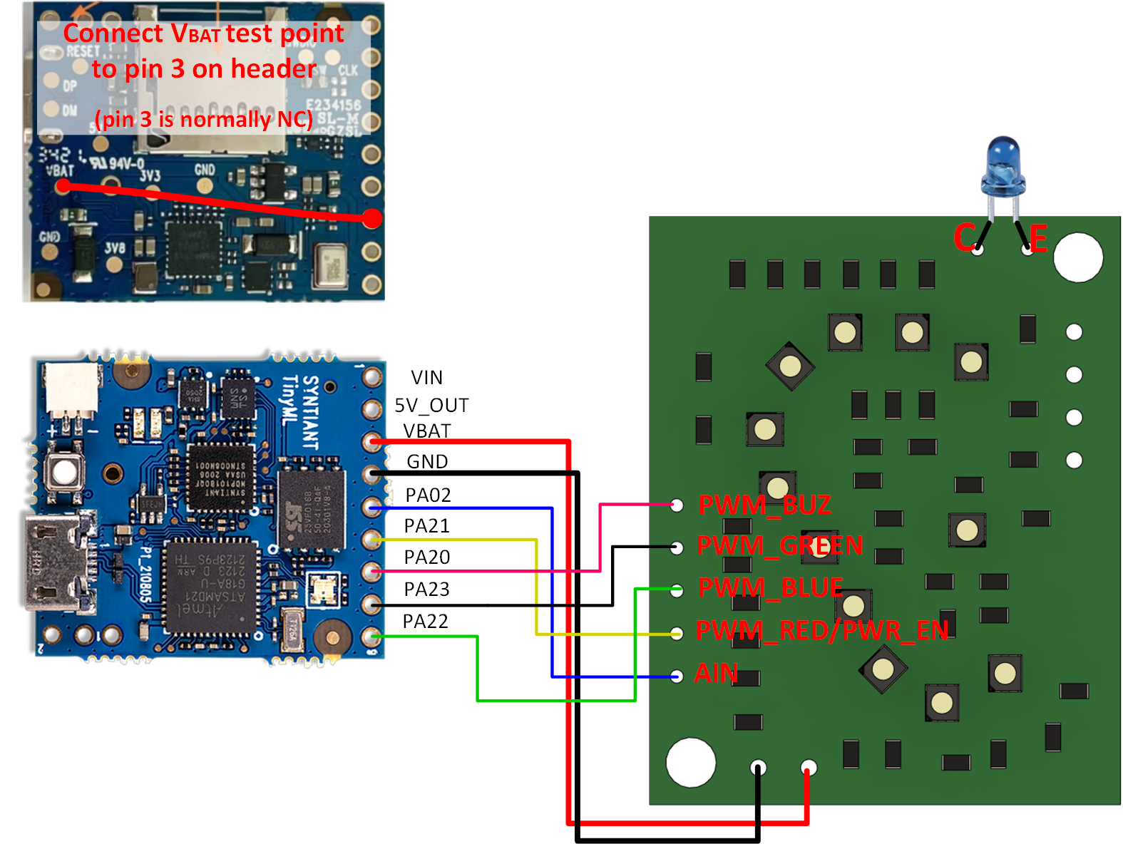
First of all, prepare the assembled LED expansion board and new TinyML board from Syntiant. You will need to make a small change on the TinyML board - connect Vbat test point (battery voltage) to an unconnected (free) connector pin. This will serve later as a supply pin for the LED expansion board. Follow the wiring diagram as in the picture below.
![]()
-
2Solar panel + charger and battery assembly
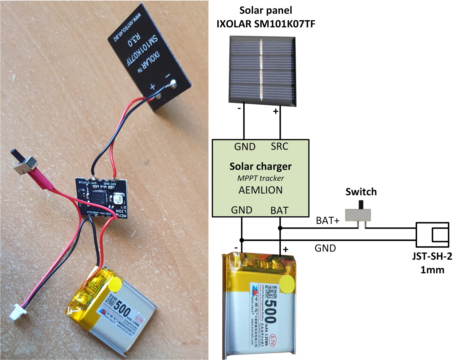
Prepare another separate assembly where you connect the solar panel, AEMLION solar charger module, power switch, and Li-pol battery together. Follow the wiring diagram and picture for reference below.
![]()
-
33D print instructions
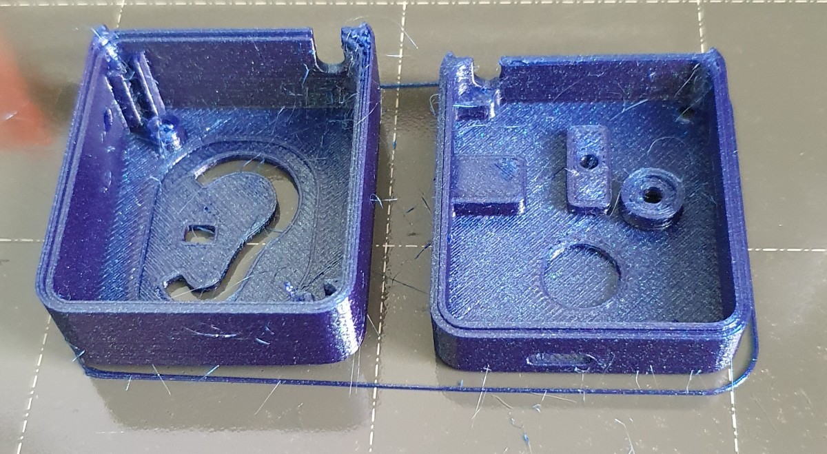
Few instructions for the 3D printing of the provided housing. Preferably use PETG material for printing the housing and car holder because of its higher temperature resistance, which is advantageous for use in the interior of the car. For reference I have used: Spectrum PET-G Stardust Blue. Print both parts oriented by face on the SMOOTH print sheet (do not use textured sheets).
![]()
-
4Light diffuser for illuminated logo
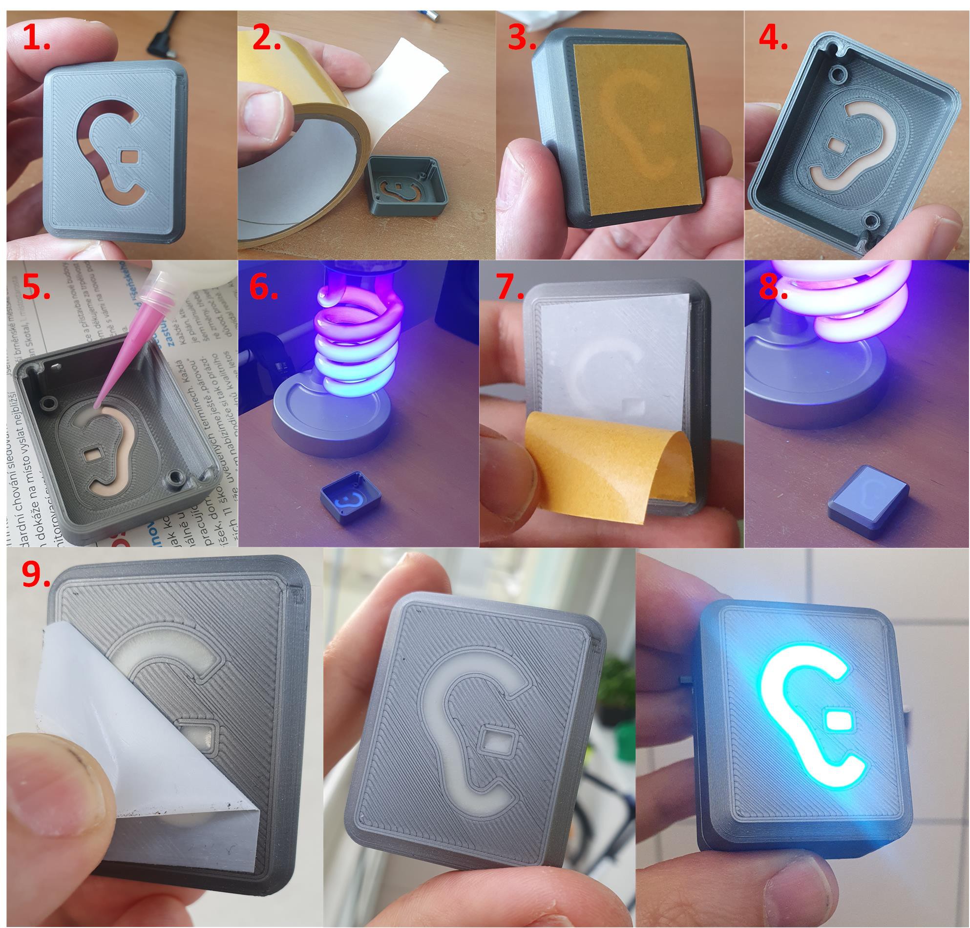
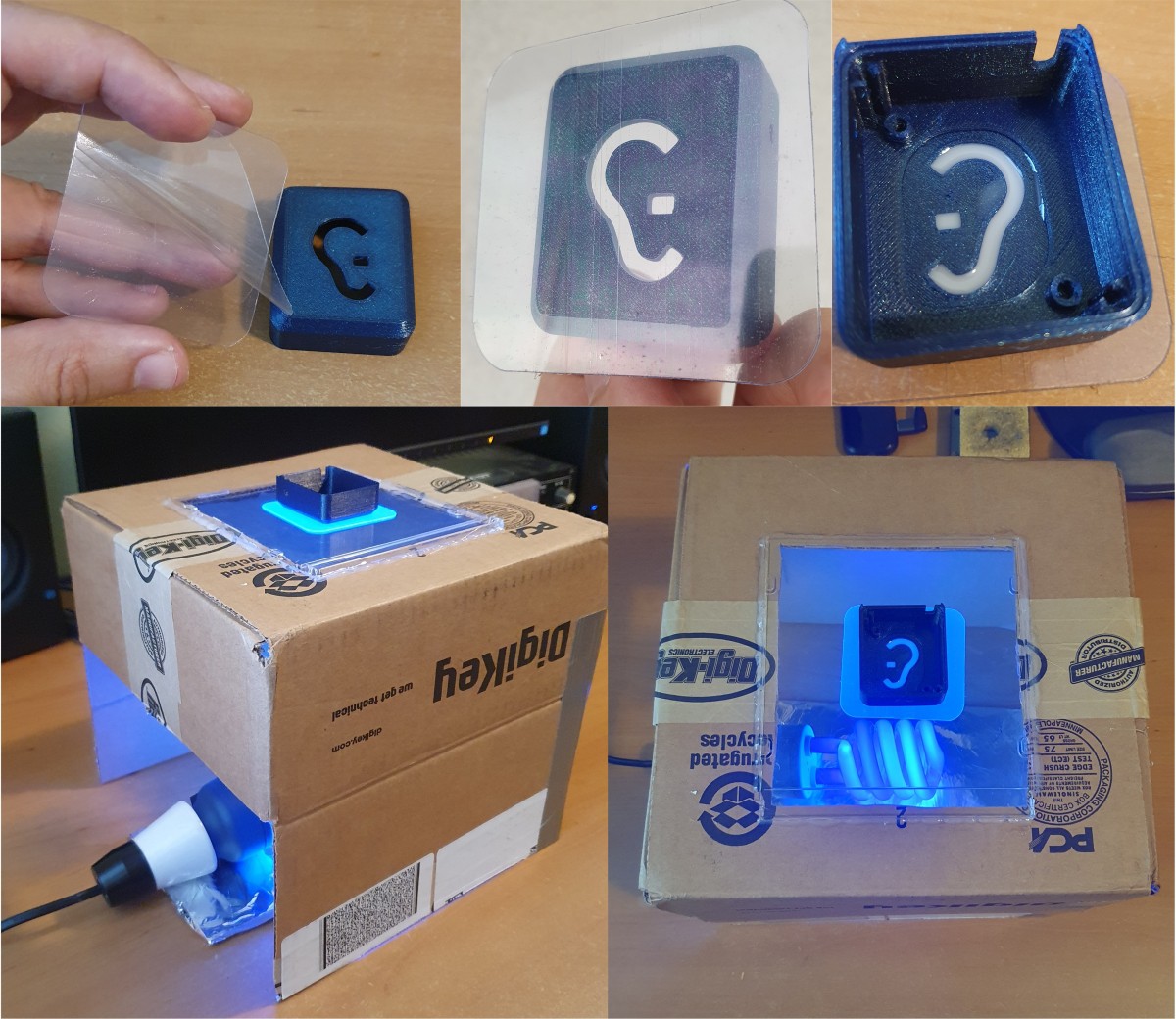
Some of my friends have been asking, how to create an illuminated logo or symbol in 3D printed enclosure. I've been experimenting with FDM print and UV resin for SLA printers. In the end, I came up with a way that works pretty well for my project. Below are some steps to be followed:
- Print your logo/symbol in negative. The wall thickness is 1.5mm in my case. Use only smooth print sheet (not textured one).
- Use some tape to cover the logo from one side. I have used double side tape because it seemed to be well covered by glue and was very sticky.
- Carefully fill the logo with white UV resin for SLA printers. Try to avoid any bubbles.
- Put under UV light. I have used UV10A: 15W, 850lm, UVA + UVB. Put at least 10 to 15cm below, but not much closer. I have experienced that bubbles started to form in resin when I was too close to the light source. Cure about 3 to 5 min.
- Illuminate from the other side too after peeling off the tape cover for another 3 to 5 min.
- Peel off the rest of the tape, clean with IPA
![]()
-
5Light diffuser – update
During the next iterations, I have been facing repeating issues with bubbles forming in the logo resin. For that reason, I have updated the previous procedure a little bit:
- -Now I use fully transparent tape/sticker. It is better to choose a more rigid one, as during the curing process the tape may start to deform. Good choices are so-called “Double-sided Tape Nano Stickers”
- -I am now illuminating the logo from the bottom side. This helps to keep bubbles out of the view surface. For this, I built a simple tool from a carton box and a transparent plastic CD cover.
![]()
-
6Insert the magnet and rubber o-ring
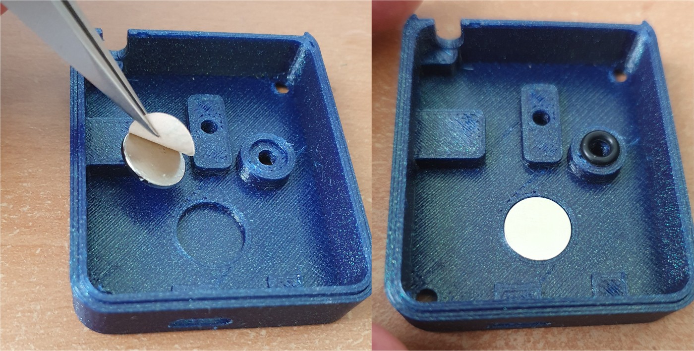
Insert the magnet into the bottom part of the housing. I use neodymium magnets of size 13x1mm with a sticker surface. Then place the rubber o-ring on the top of the microphone hole.
![]()
-
7Installing the TinyML board assembly
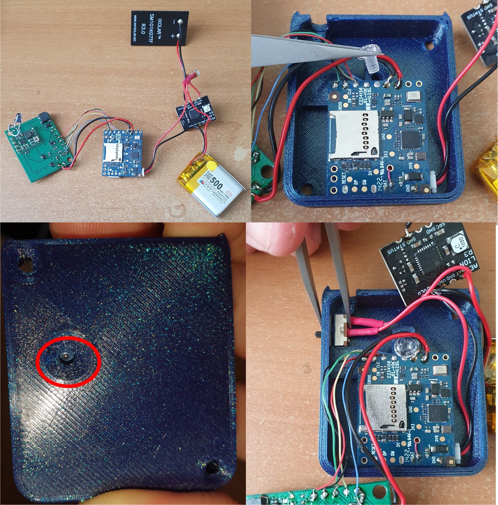
Prepare assembly from step 1 and connect via battery connector the assembly from step 2, so all parts are interconnected together. Then place the TinyML board into the prepared bottom housing part from the previous step. Secure it with plastic Screw M3x5mm. Check on the opposite side that microphone port is aligned with the hole. Insert and press-in the switch into the switch hole. No glue is needed, the tolerances are tight enough to keep the switch in its position.
![]()
-
8Double side tape
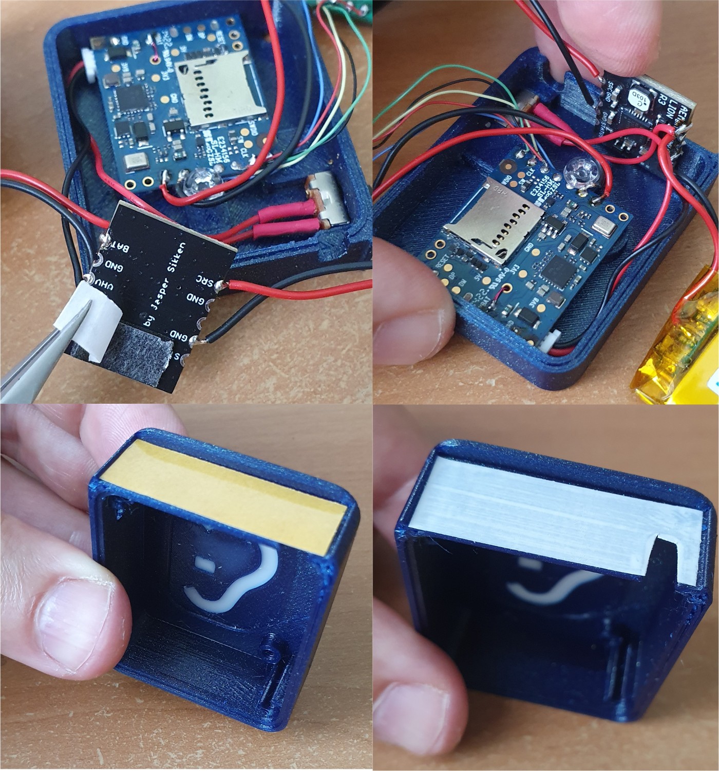
Use a small piece of double side (foam) sticker on AEMLION board (solar charger) and stick it to the position as in the picture. Then use a thin version of double side tape on the top housing cover – make a cut-out for solar panel cables.
![]()
-
9Solar panel Installation
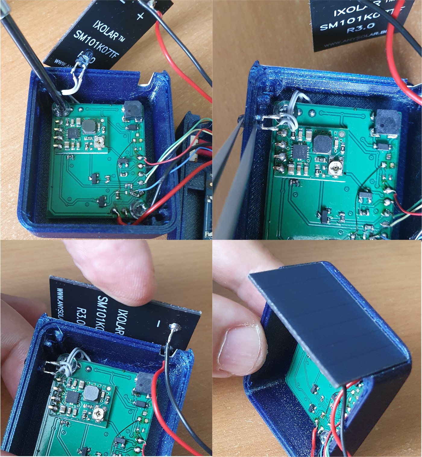
Insert LED expansion board into the top housing cover and secure it with two M3x5mm plastic screws. Push the light sensor (phototransistor) through the hole – tolerances are again tight enough so no glue is needed. Then stick the solar panel on the top of the cover where double side tape is prepared as shown in the previous step.
![]()
-
10Final sensor housing assembly
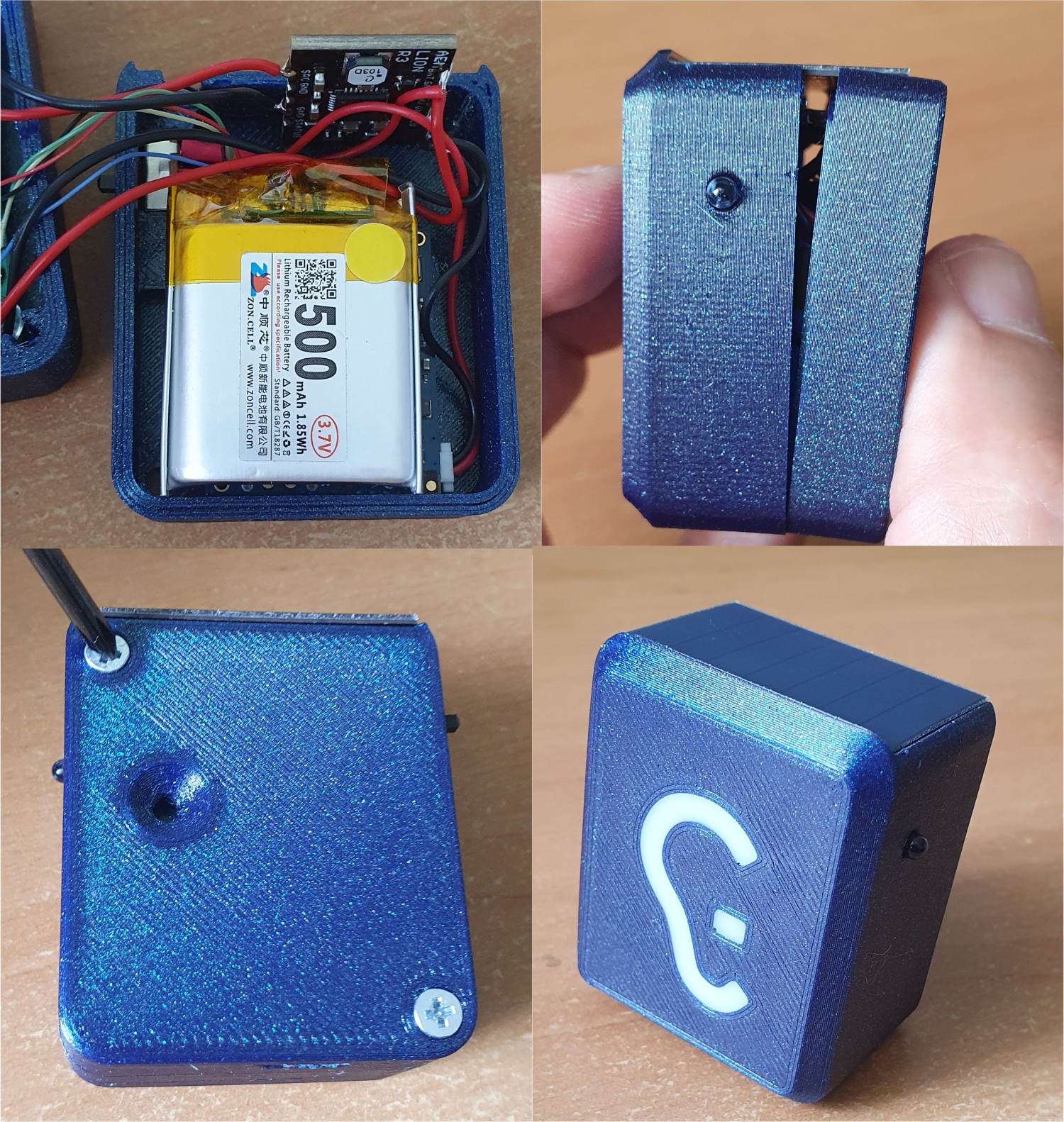
Place the Li-pol battery on the bottom housing part as in the picture. There is no need for battery fixation, the assembly is tight enough to keep the battery in its position. Then put both parts together and secure them with two M2.5x16mm screws.
![]()
PionEar: Making Roads Safer for Deaf Drivers
PionEar provides early warning to deaf drivers of an approaching emergency vehicle
 Jan Říha
Discussions
Become a Hackaday.io Member
Create an account to leave a comment. Already have an account? Log In.