DominicM
-
Parts have arrived!
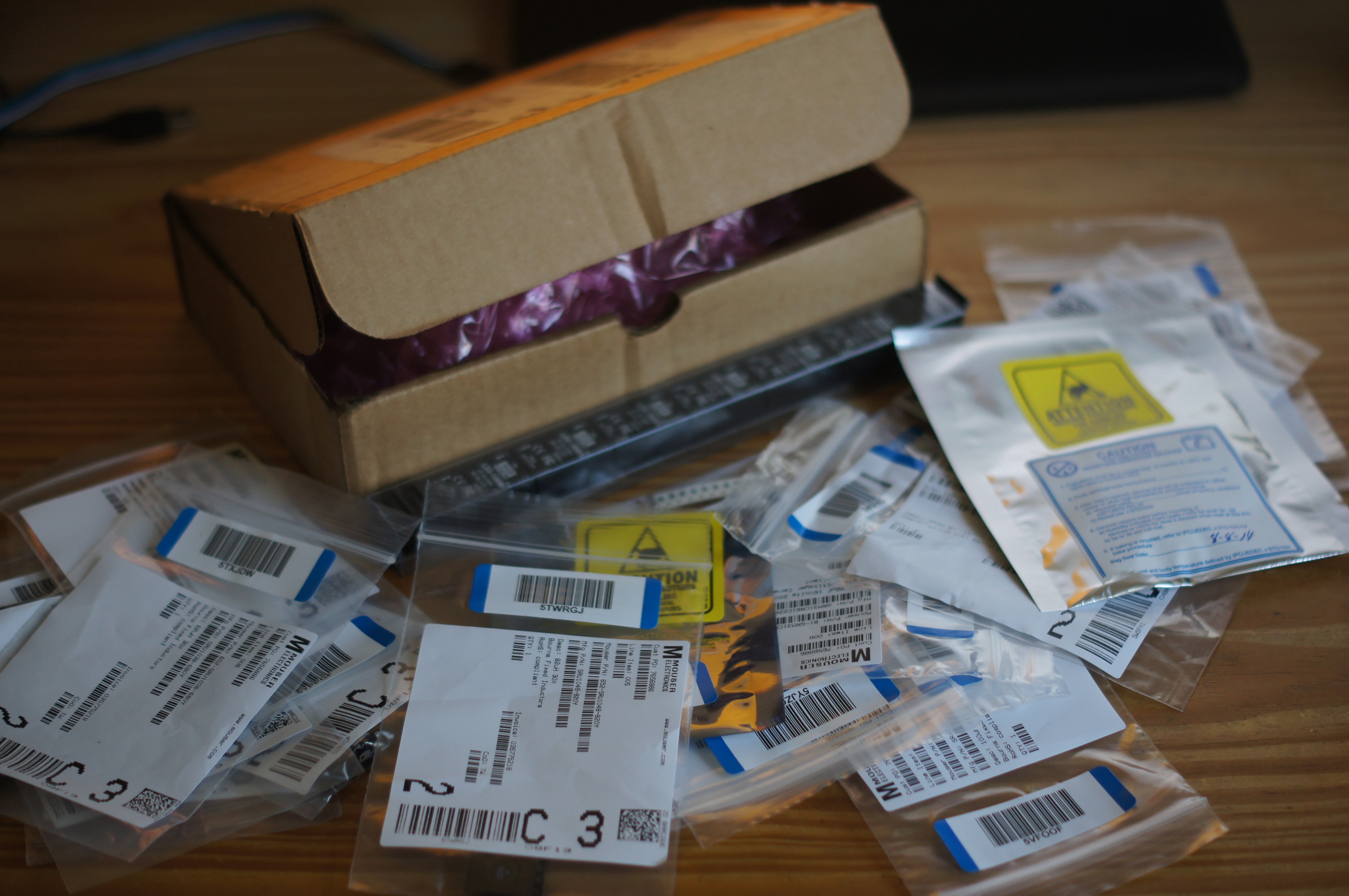
08/15/2014 at 19:45 • 0 commentsSome parts have arrived mainly for the PCB of the voltage regulator. Will be attempting to make the PCB and assemble the switching voltage regulator soon! After that will move on to the larger PCB that will eliminate the need for external, non-PCB mounted components.
![]()
-
Schematic
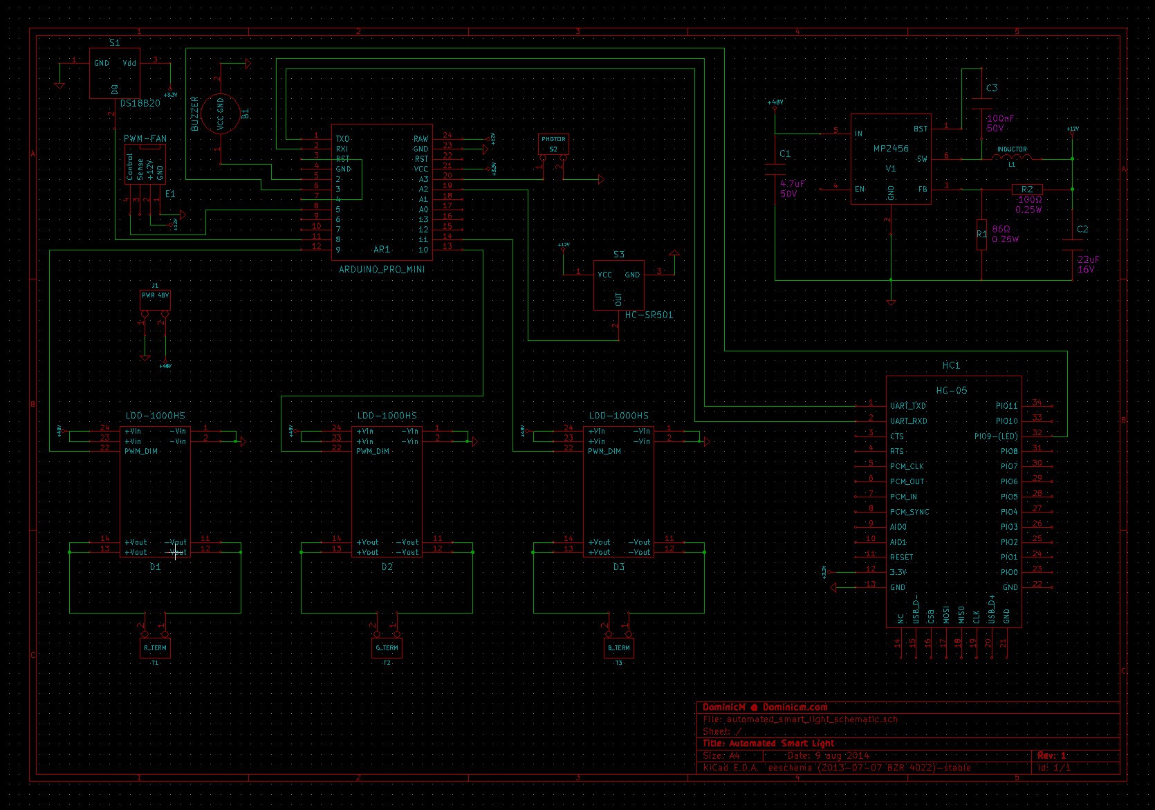
08/12/2014 at 23:29 • 0 commentsI have posted a preliminary schematic for the project. It includes parts for fan assisted cooling though I am currently using a larger heat-sink instead of the fan and temperature sensor to reduce noise and complexity. Note that some parts in the schematic are different from what is currently shown in the pictures and video, this is due to design changes to be implemented soon.
I am awaiting parts and will be soon attempting to build the voltage regulator and then the remainder of the board.
![]()
-
Mood lighting feature (video)
08/04/2014 at 22:45 • 0 commentsTwo new display modes have been implemented - color cycle and fade. This essentially allows the smart light to act as a mood light as well. Check out the quick video below:
-
Design changes (3D visualization)
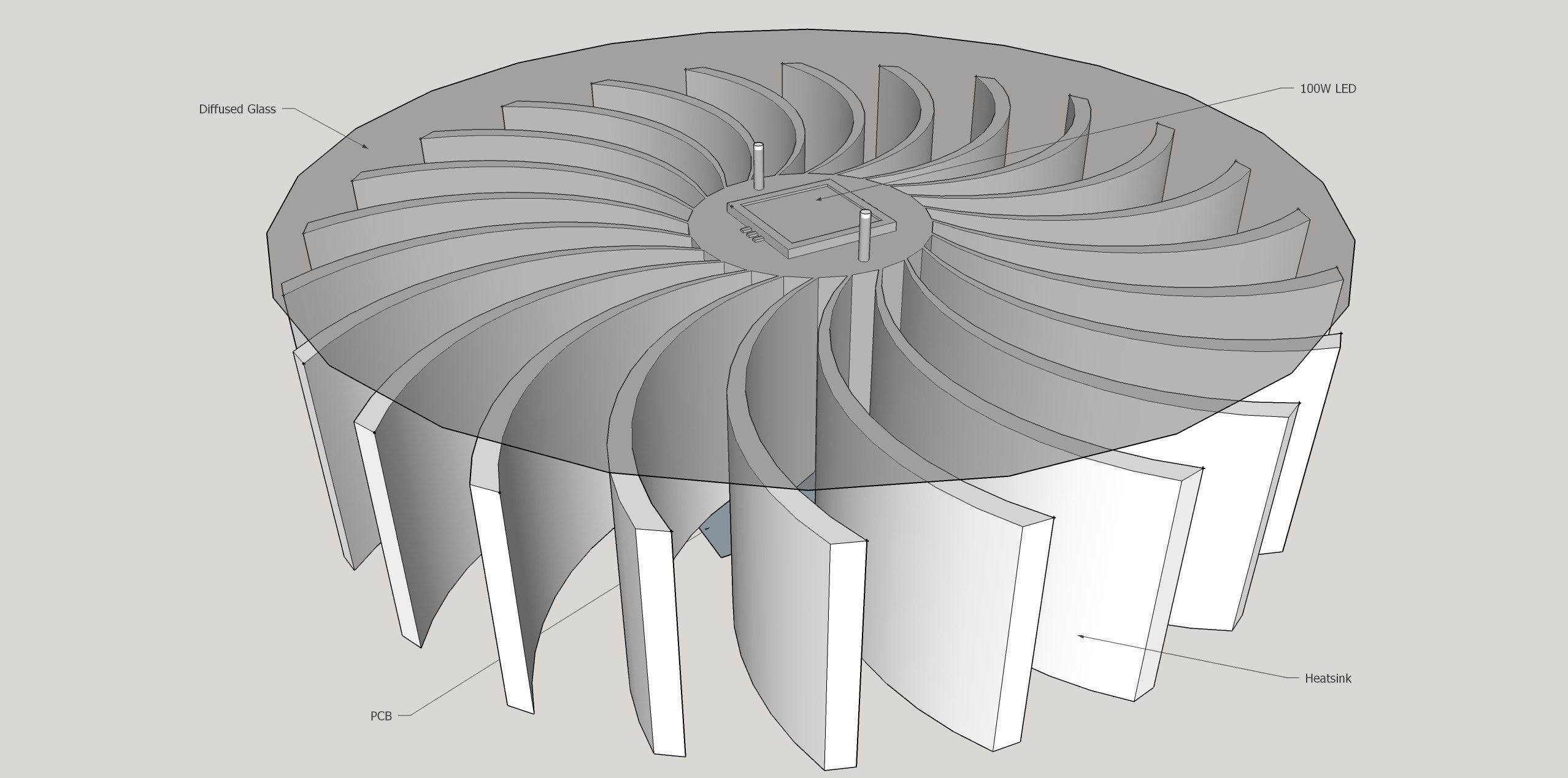
07/18/2014 at 13:54 • 0 commentsHere is a simple 3D render of the initial physical design and layout for the light. The main components in the image are:
- Heat-sink
- 100W LED
- Diffused glass cover
- PCB
![]()
The goal with this change is to solve some of the problems with the first prototype, mainly the noise from the fan, glare from the LED and the large overall size.
The fan has been replaced with a large heat-sink making the it 100% silent. Diffused glass was added to reduce glare at high power settings. The power supply will likely be in the form of an external AC-DC adapter. This will only leave the relatively small PCB that can attach to the back of the heat-sink.
Automated Smart Light
Automated, Bluetooth connected, high power RGB LED light with automatic luminosity matching, motion detection and more...