-
3 Dec 2023 - (1) Power supply
12/03/2023 at 13:39 • 0 commentsOK this is still phase 1 - the power supplies. At this rate it will take several years to finish the project!
Anyway I realized that when battery-powered tube-based audio amplifiers drive loudspeakers, they need negative bias for the tube grid. And today I'm calling them tubes not valves. Usually this -ve bias is obtained from yet another battery, either called the C supply or just a grid bias supply. In the distant past, grid bias batteries were a thing you could buy. Here is someone making a reproduction grid bias battery
In this project the audio amplifier is experimental - this means I haven't designed it yet. I will need a variable bias pack. Basically it's a variable resistor and switch across a 15v battery:
![]()
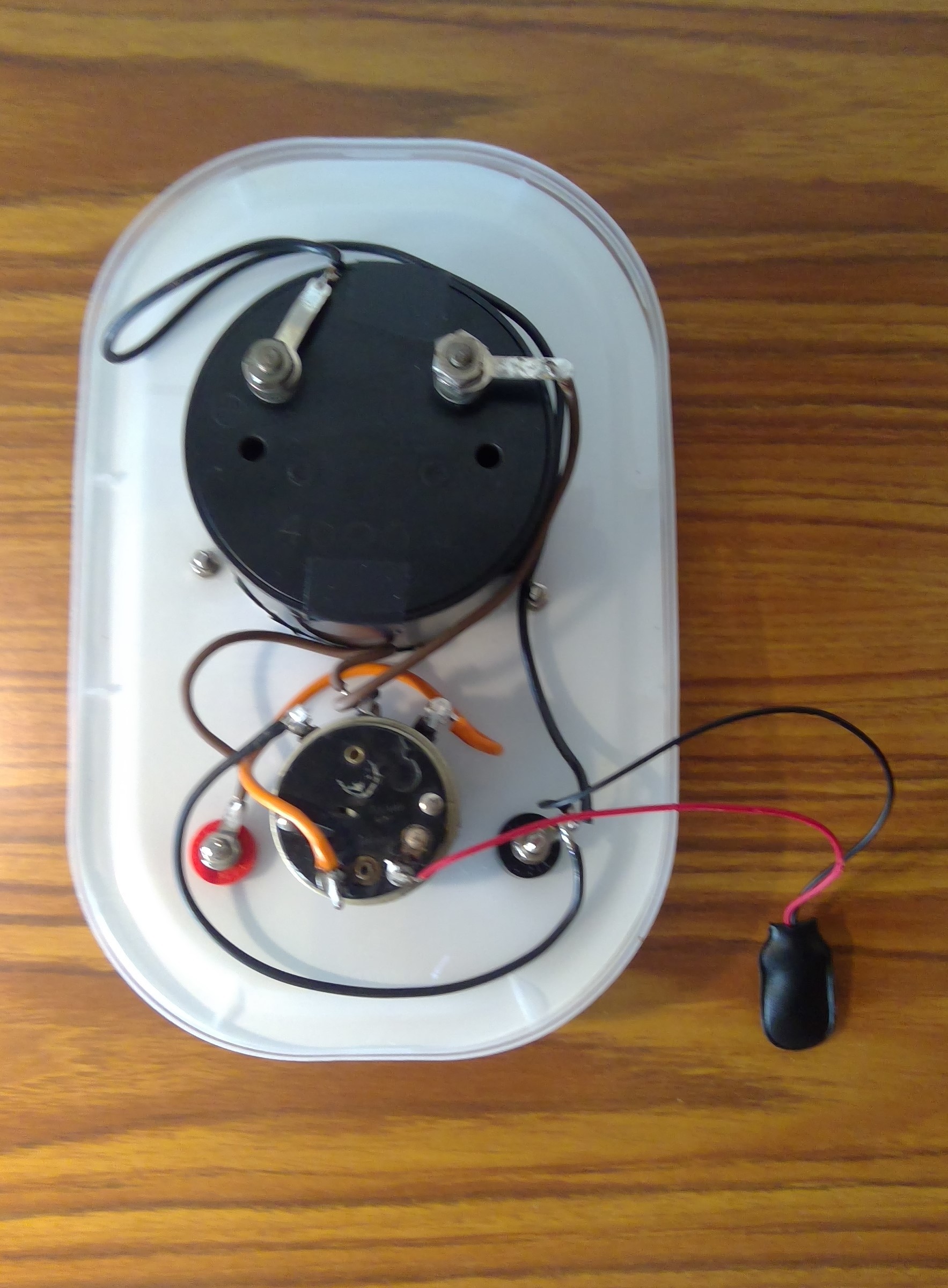
Here is a picture of the insides (the large black blob is the rear of the meter and the small black blob is the potentiometer):
![]()
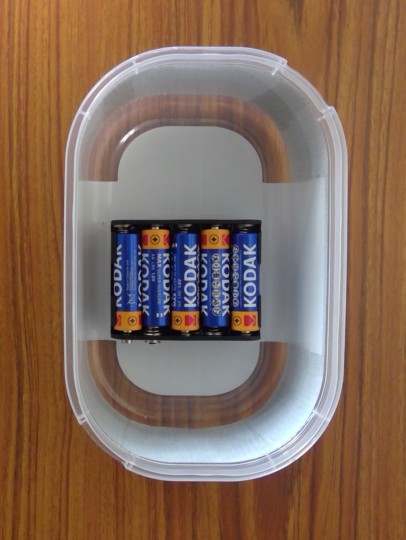
And here's the battery. I fastened it to the container with some bluetack and the battery snap in the above picture clips onto it:
![]()
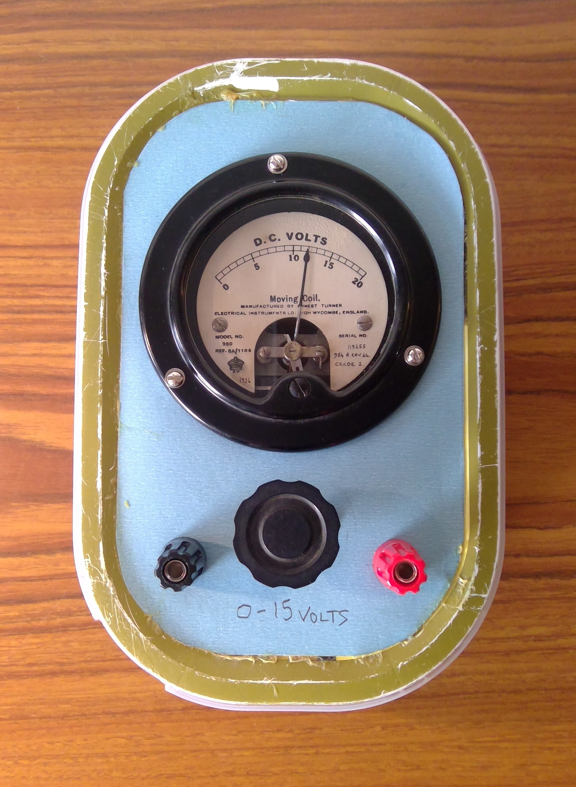
And here's the final result outputting 12v:
![]()
This is designed as a variable voltage source to help with experiments, it's not an actual power supply and it's not designed to output any significant current. That's fine for battery tube audio amplifiers as they generally operate in class A (or AB1) where the grid is not driven positive.
As a "tube refresher", if the grid is always negative then no grid current flows, and the varying grid voltage causes varying anode current. If the grid is driven positive some current flows from the cathode (source of electrons) to the positive grid, thus grid current flows. Some tubes are designed for their grids to be taken positive as it can improve performance, but it means the driving stage has to provide some power.
Tubes allowing grid current are "power" tubes designed to give larger outputs. They are sometimes called "Class B" tubes as they are generally used in pairs for push-pull output. In most cases they are mains powered. But there are a few exceptions where there are two battery powered tubes in one envelope, intended to be used as a class B audio amplifier. One such tube is the type 19 twin triode, and I hope to experiment with this later on.
Also I'm not 100% happy with the "ice cream" tub containers, as they are a bit flimsy and their rounded shape does not make good use of space. In hindsight maybe I should buy some nicer plastic enclosures.
Anyway, this should be the end of the power supply experiments. Time to move onto stage 2, the audio amplifier!
-
5 Nov 2023 - (1) Power Supply
11/05/2023 at 17:02 • 0 commentsOK so I'm following the four stages that I logged earlier today - Stage 1 is the Power Supply.
This project uses batteries for all its power supplies, avoiding the danger of electric shock that exists with mains-based high voltage power supplies. Battery valves use lower voltages (potentially down to 12 volts or even lower), and they allow me to use breadboard type construction. Breadboard construction is easy to do and looks really good with the radio valves. Breadboard construction isn't suited for mains-powered valve projects as there's no protection against casual contact with high voltages.
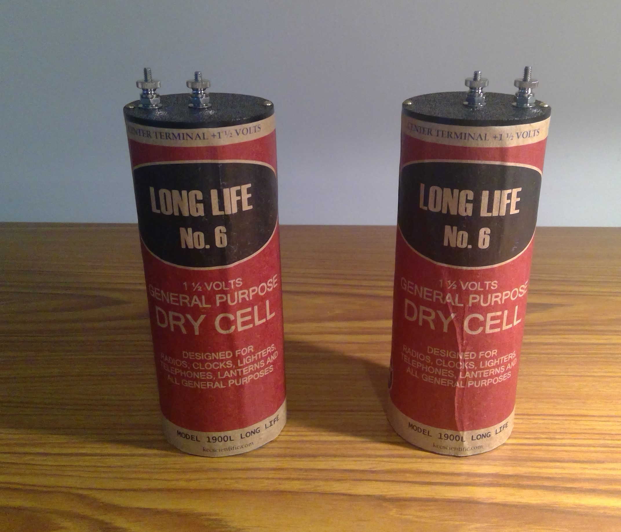
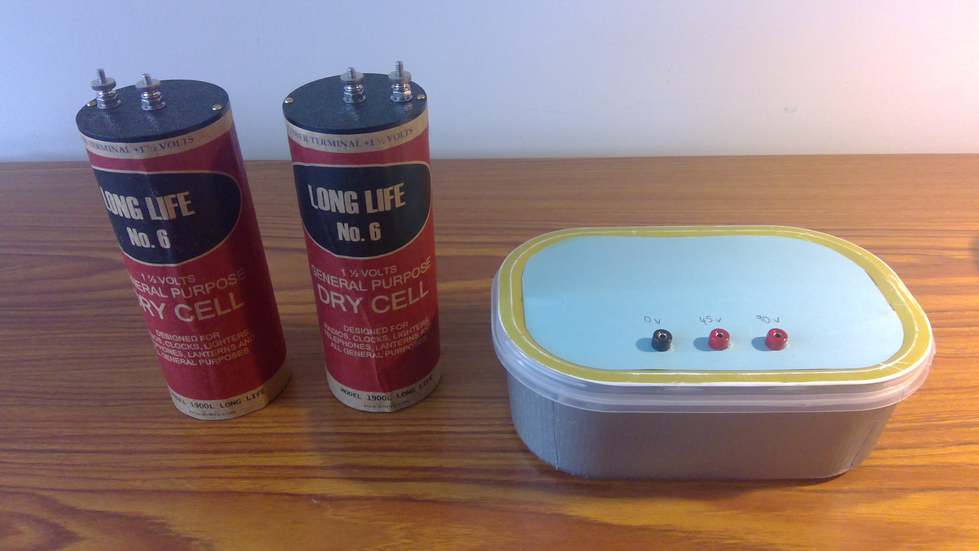
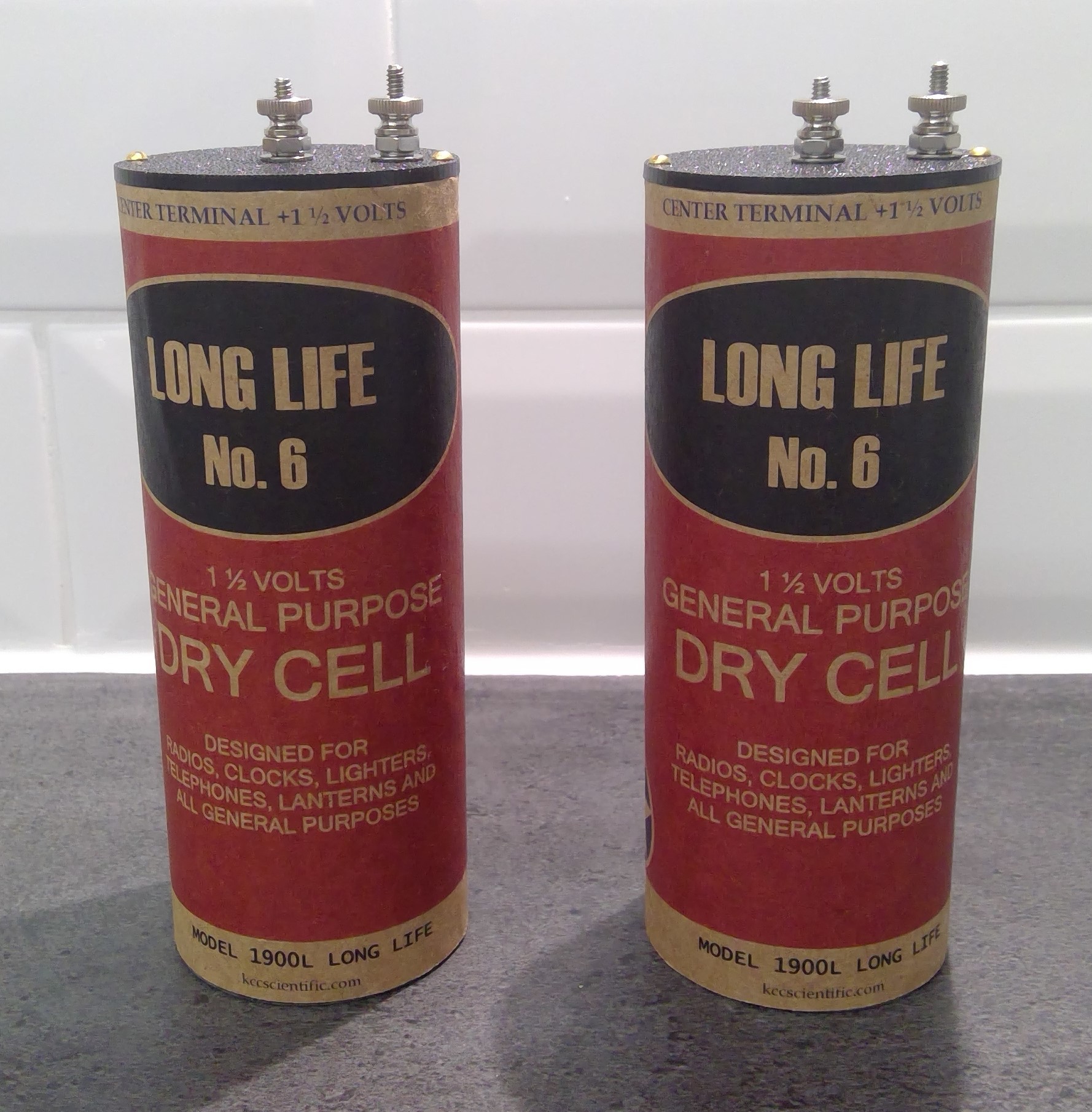
So, here is the LT (low tension) supply for the valve filaments. I bought these monsters a while ago, they are 1.5v each and they both go in series with a rheostat to provide 2v for the filaments. They are called no. 6 batteries because they are 6 inches tall - and they are simply a single large battery with a positive center terminal and a negative outer casing:
![]()
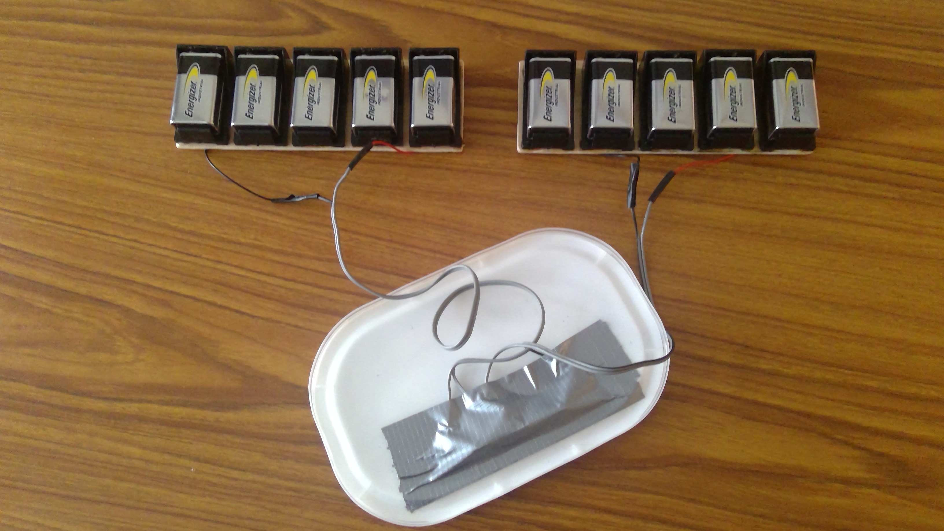
Next is the HT (high tension) supply. These consist of strips of thin plywood (17cm x 6cm) with five individual 9v battery holders glued on with epoxy. On the underside of the plywood, the battery wires are soldered in series and covered with tape. Therefore each strip of plywood makes 45v. I wanted to make three of these allowing 135v but I only ordered 10 battery holders so I will have to make do with 90 volts for now. Also I would need a bigger battery box for 135v.
![]()
The PP3 batteries are not very large and you could argue for AA batteries instead. AA's would last longer but I would need 60 to make 90v. Some time ago I made a 90v battery pack using AA batteries - it worked well but because there were so many batteries, you only needed one dodgy battery or loose or corroded contact, and the battery box would then create a lot of noise that was difficult to trouble shoot. PP3's are approx. 500 mA/hr so if we limit HT consumption to 10 mA they should last for 50 hours which I think is OK.
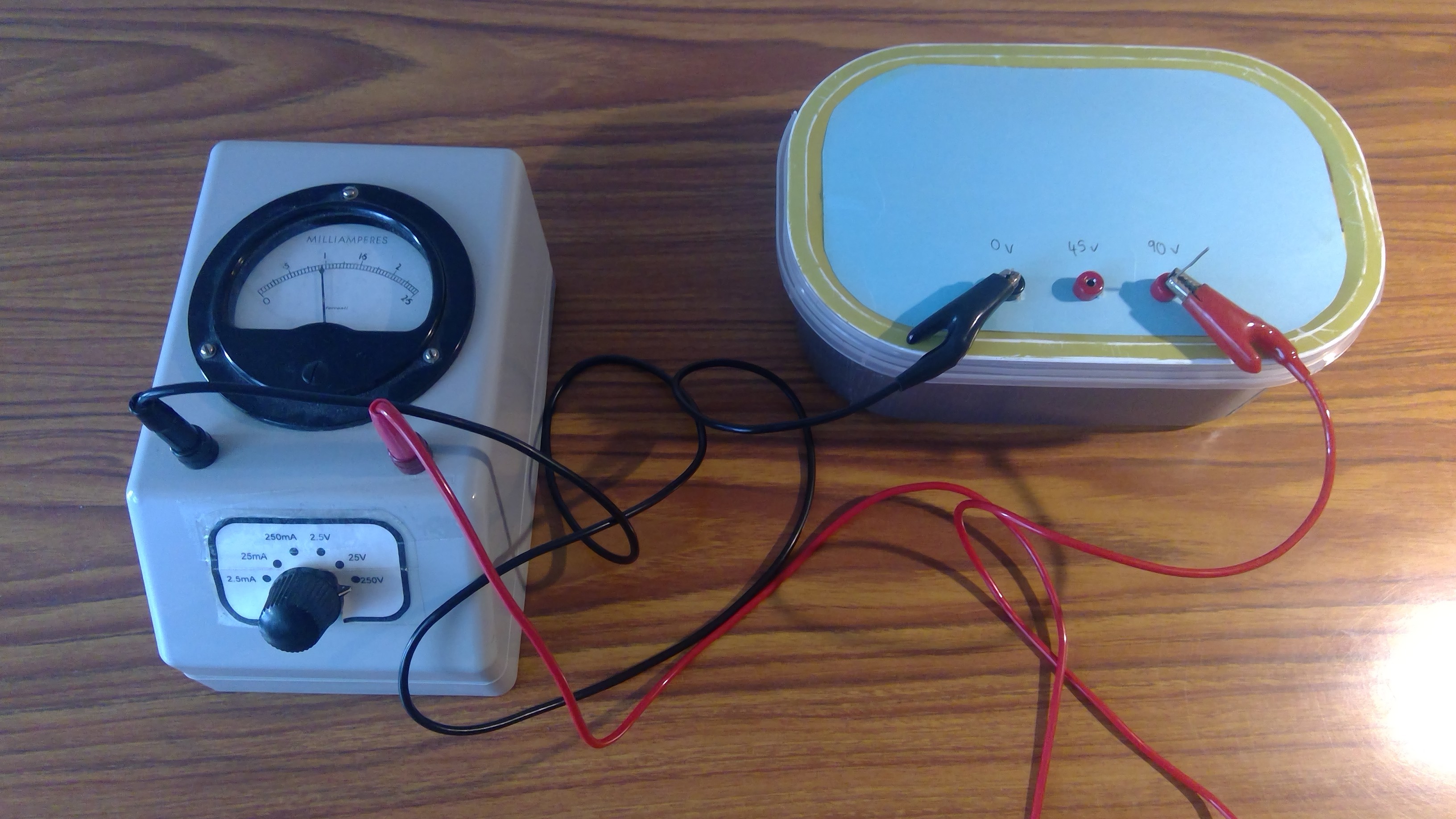
Anyway, after putting the battery holders inside the battery box, here's a meter measuring 90v:
![]()
The battery box measures 18cm x 10cm deep x 6cm high, and any resemblance to an ice cream carton is purely coincidental! Ideally I would get a proper box that looks more like an old-style HT battery and has room for three of the 45v assemblies, but I couldn't find one.
Here are all the power supply elements together:
![]()
When I look at the size of these I realize transistors maybe aren't so bad after all :)
These power supplies don't have to follow what I did. As long as you have a LT supply for the filaments and an HT supply for the rest of the circuits, it will be fine. LT should match the valves you have, and HT should be 90v to 135v for loudspeaker reception, or can be 12v to 45v for high-impedance headphones. People that build reproductions of early-style valve radios sometimes fasten battery holders to the breadboard, and they clip 9v batteries to one another to make the HT.
-
5 Nov 2023 - Future Plans
11/05/2023 at 12:28 • 0 commentsOK I haven't logged here for a while - some real life things got in the way, plus I had to order some audio transformers. I had a think about the general approach to this project, and I think there are 4 main steps:
- Power Supplies. I need low voltage supplies (LT) for the valve filaments. Depending on the type of valve these need 1.5v or 2v. Also I need high voltage supplies (HT) for the anode circuits. These can be anything from 9v to 45v for amplifiers that drive headphones, and 90v to 135v if I want to drive a loudspeaker. Some circuits also have a grid bias battery, this provides negative bias and is generally needed for output circuits that drive loudspeakers.
- Audio circuits. This will be an audio amplifier that will take a 1v RMS audio signal (that's 1.4v peak, or 2.8v peak-to-peak). I think this is the same as "line out" voltage from the 3.5mm connector on laptops and PCs and possibly CD players. The audio circuit will amplify this signal and drive a small loudspeaker. Also it's possible to design a simple amplifier that drives headphones.
- Detector. This is the radio frequency tuned circuit and regenerative detector that uses a single valve. It feeds some of the amplified output back to the input, generating positive feedback and increased gain. This is also called reaction and was the earliest type of RF detector that could also produce some gain.
- Packaging. When the above steps are done I will put all the parts together and make them look nice. There are two basic types of radio receiver - one that drives headphones and the other type that drives a loudspeaker. The advantages of using headphones are simpler circuits, possibly using less valves, and not needing as much voltage in the way of HT.
I will continue to use breadboard construction for this project, as it's easier to work with and there are no dangerous high voltages. All the power will be provided by batteries.
-
29 May 2023 - Tube Sockets
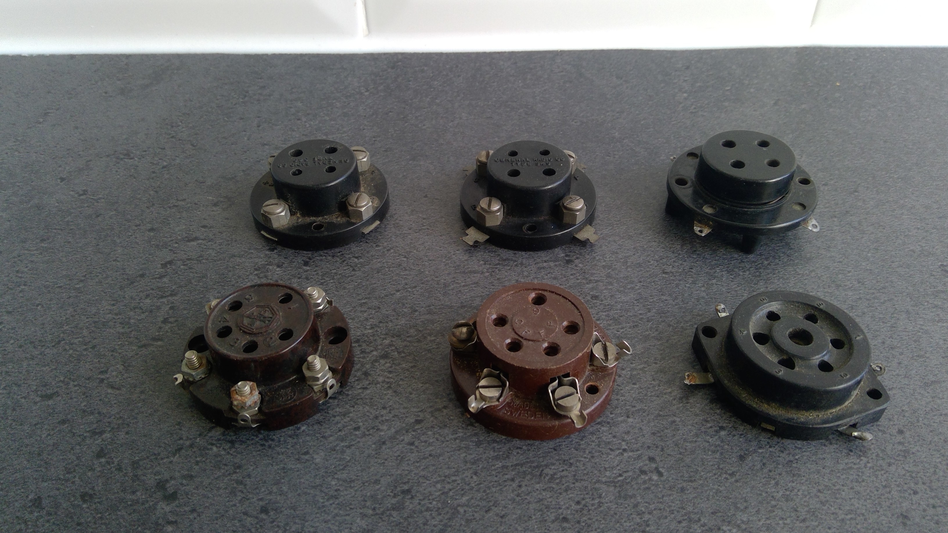
05/29/2023 at 16:06 • 0 commentsTube sockets (also known as valve sockets) come in two main forms: chassis mounting which is where you make a circular hole in a metal chassis and fasten the socket to it, or breadboard mounting where you fasten the tube socket to a wooden breadboard. The majority of tube sockets are chassis mounting because the metal chassis helps screening between circuits. But the breadboard mounted sockets are easier to work with because you don't have to make a large circular hole. Here they are:
![]()
You can see the 4 pin sockets at the back of the photo, and the 5 and 6 pin sockets at the front. These were difficult to find, and if you're building this project it's perfectly fine to use chassis mounting sockets and spacers, to hold the socket above the breadboard. But I think the breadboard sockets look better.
The 4-pin sockets are called UX-4, the 5-pin UY-5 and I think the 6-pin is UZ-6. Actually I'm not sure about the last two, you could probably call them UX-4, UX-5 and UX-6.
In early radio construction you didn't need a soldering iron because the sockets used thumb screws and the circuit could be built by wrapping solid core wire around the thumb screws and nuts and bolts. But I couldn't find any using thumb screws so I will have to use the soldering iron.
-
17 May 2023 - Beauty Parade!
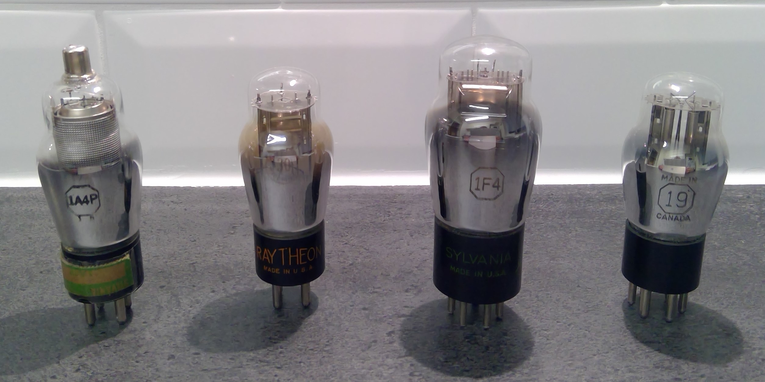
05/17/2023 at 21:29 • 0 commentsI bought most of these a while ago but here they are:
![]()
Presenting from left to right:
- 1A4P - a pentode with a 4-pin base, the top cap is the control grid.
- 30 - you can just see the "30" on the glass, this is a low power triode with a 4-pin base.
- 1F4 - a "power" pentode with a 5-pin base, able to put out 0.5 watt of audio at maximum ratings :)
- 19 - a double triode with a 6-pin base. This can be used as a class B audio amplifier to deliver a mighty 2 watts of audio!
Some interesting facts I learned:
- The earliest vacuum tubes had a two-digit numbering system (30, 19 etc etc).
- In the 1930's was a "newer" system number letter(s) number where the first number is the heater voltage (approximately), the letters are arbitrary and the last number is the number of electrodes. The 1F4 uses a last number of 4 because it has the filament, control grid, screen grid and anode, and the suppressor grid is internally joined to the filament.
- All these have 2 volt filaments designed to run from batteries, either a lead-acid cell or a higher voltage fed through a fixed or a variable resistor. When a variable resistor is used, it was called a rheostat and it was adjusted to allow for declining battery voltage during use.
- The filament is very thin and it runs red-hot (or nearly red-hot) and emits electrons, usually just a few milli-amps. A common mistake when using these valves is applying too much voltage to the filament, which burns them out and makes the valves useless.
- Any of these could be used as the regenerative detector, or as a low power audio amplifier to drive a pair of headphones.
- The "power" pentode and the double triode were designed to drive loudspeakers using audio transformers.
- Some simple radios used the 19 double triode as a regenerative detector AND an audio amplifier. Thus making an entire radio from one vacuum tube.
And some terminology:
- These battery valves are directly heated, meaning current is passed through a fine coated wire causing it to heat up and to emit electrons. This heated wire is the cathode and is also called a filament (USA) or a heater (UK/AUS).
- Vacuum tubes (USA) or radio valves (UK/AUS) are different names for the same thing. Sometimes I use one and sometimes the other.
- Valves have an anode which is positive, similar to the collector of an NPN transistor. The anode (UK/AUS) is also called the plate (USA) and collects the electrons emitted by the cathode.
-
15 May 2023 - Low Voltage Batteries
05/15/2023 at 21:17 • 0 commentsEvery project starts with a single step and I have been thinking about this project for a while. The vacuum tubes / radio valves in this project have 2 volt filaments, although alternate tubes/valves can be used that have 1.5 volt filaments. The 2 volt valves were "early" valves designed for lead-acid accumulators and the 1.5 volt were "later" valves invented around the 1940s for dry batteries. So I decided to order two "old-style" 1.5 volt batteries to cover both scenarios - if I use the 2 volt valves I will put the batteries in series and use a resistor to drop the voltage to 2 volts.
I think these are called No.6 batteries because they are 6 inches tall:
![]()
You can read more about them here: http://prc68.com/I/No6.shtml
They are also used in electric clocks and I bought these from https://www.kensclockclinic.com/our-no-6-batteries/
It's perfectly OK to use 1.5 volt D cells and buying these No.6 batteries was a bit extravagant. But they look suitably retro!
Portable Radio using Vacuum tubes / Radio Valves
Create a radio receiver using vacuum tubes (aka radio valves). It will be portable, using available parts, and will look cool :)