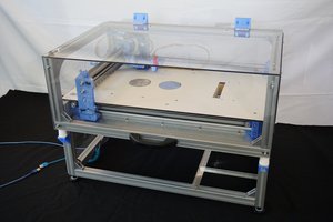
Last summer when I visited my relatives, I noticed that my uncle started having hearing loss, and to communicate with him seemed like a difficult task. He is a wise, practical man, but with the hearing loss, it gave the impression that his reaction has become slow and wisdom has faded. So I bought him a pair of hearing aids, and it wasn’t good enough, squealing comes quite often, and he also doesn’t like the look of wearing hearing aids. Since I was working on an audio processing project, I thought why not make an earphone but with amplification functionality (at the time of starting project, there was no such product in the market yet), with dynamic range compression, feedback suppression and noise reduction, so I can also warm up my skill and get some fun.
I started to look into the solution, main processor should be small, yet powerful enough to process audio signal in real time. After a lot of research, I ended up using nrf52 series chip. It supports BLE protocol, so it has no classic connection to cell phone, but to process audio, it is good enough. So in short, I made this:
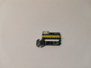
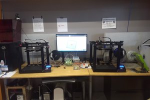
Then the challenge comes, to make it small, I have to use tiny components, e. g. 0201, and every 0402 component I used took up a lot of space. To mount those tiny components, it felt like my eye will explode even with the microscope. I started to look for a way that can help me place the parts. PNP machine is a natural direction, but the ones on the market are very expensive. I happened to have an 3D printer at my hand, so I started to make modification and hack around my 3D printer.
There are multiple aspects for converting 3D printer to PNP machine,
- Accuracy – when looking at the specification from a 3D printer, position accuracy is 0.0125mm, in reality, I found it not really able to achieve such accuracy, for me it can move to specified location consistently within 0.1mm, and that is good enough for me.
- Connectivity – With a PNP machine one usually needs to connect to a PC and run G-Code commands. Most of 3D printers have USB interface. Then it also needs to connect an air pump, which means G-Code controllable interface is needed. The same applies for the lighting of the camera. So the more control interface it provides, the better.
Nozzle head
So as the first step, I need to find out what can be used as the nozzle tip and how to hold it. By searching in the internet, it came out that fluid dispensers can be a good fit, it has multiple sizes, from as low as 0.06mm to greater than 1.0mm inner diameter. It is strong and durable enough to support repeat pickup and place operation.
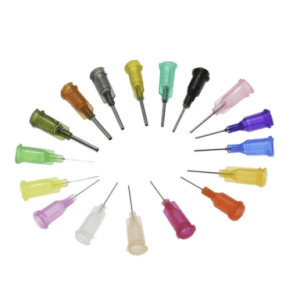
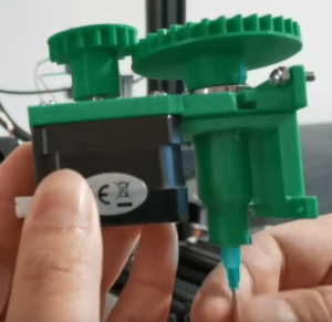
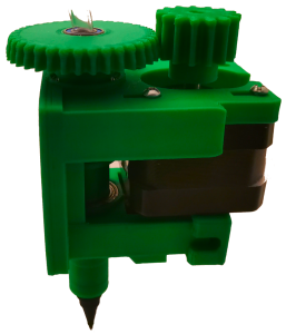
To use the fluid dispenser head, we also need something to hold it, so I designed the 3D printed nozzle head to hold the dispenser. After a bit of trying and error, the design came out as this.
It has a gear on top of the head, then a stepper motor (nema 17, 1.8 degree) can connect to it and drive the rotation. One bearing is used to make rotation easier. Then there is a screw thread inside the end of the nozzle head to make sure it can hold the dispenser needle. I was worried about the air leakage, but after printing couple of the heads and testing out, it can hold the air inside pretty well.
Then in order to mount the head onto the 3D printer, I need to find some place that is strong enough and easy to mount. Luckily there is a fan case, the idea is to make it switchable as easy as possible. So initially I decided to reuse the fan case for hot end, as it is a metal piece, it should be strong enough to hold the nozzle head.
But after couple of jobs, I found that the mounting to the fan case is not strong enough, as the fan case is supported by a piece of metal, and it could change position when some force is applied. So later I switched to mounting directly to the hot end support, but still leave the hot end, as I still want the switch between 3D printer and PNP function to be simple and fast.
After mounting the head, I ran a few tests, it can rotate the head...
Read more » xpDIY
xpDIY

 cprossu
 Miroslav Zuzelka
 John
John