Close
0%
0%

Radio-based Telemetry Receiver PCB

The goal of this project was a one way telemetry system for Formula Student car.

Similar projects worth following
Design requirements:
- Minimal range – 100m in open field. This could’ve been achieved without LNA amplifiers, but for extra reliability, it was chosen to use them.
- Transmit power: +20dBm – maximum power allowed in Europe.
- Omnidirectional antenna, with 2dBi gain.
- Transmitter placed in front of the car with other electronic components, on standardized motherboard.
- Acquired data would be transmitted to the computer, where it would be stored and analyzed.
- Transmitter and receiver would be powered with 5V
- The car is made out of carbon fiber composite, with aluminum honeycomb between the carbon fiber sheets. Honeycomb and carbon fiber are electrical conductors, so the antenna needs to be mounted outside the monocoque
- The car uses 1Mbps CAN bus, so the telemetry system should be able to transmit data with speed >1Mbps

Supported by JLCPCB: jlcpcb.com/HAR

Transmitted data:

  • Accelerator pedal position o Brake systems pressures
  • Speeds of all 4 wheels o GPS position
  • Power, that the inverter sends to the motor
  • State of charge of the low voltage battery.
  • State of charge of the high voltage battery.
  • Inverter temperature
  • Motor temperature
  • Low voltage battery temperature
  • High voltage battery temperature
  • Water temperature
  • State of the car
  • Tire temperatures

Whole project can be found here: https://github.com/PUT-Motorsport

Block Diagram of the System:

Final Layout

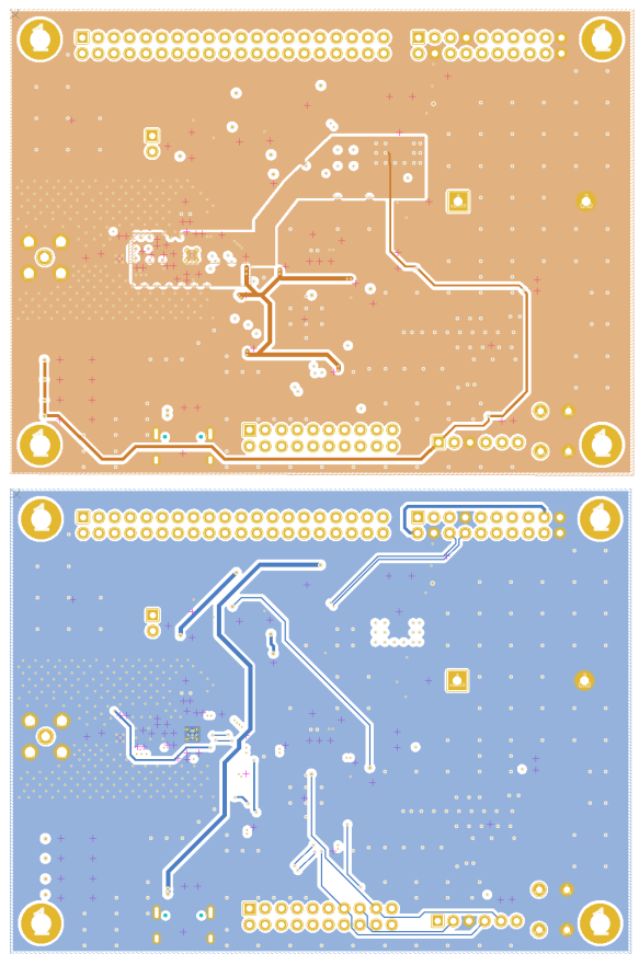
4 layer PCB was used, cause of lower distances between copper layers, and simultaneously not significantly higher cost. The ground plane was poured on every layer. The 3.3V power was routed on layer 2. JLC PCB JLC04161H-7628 stackup was used.

Final layout was designed to fit on the top of already in-use motherboard: https://www.instructables.com/Multi-PCB-Motherboard/
  • 1
    Generating .gerber files

    To generate production files you need to export a .zip folder with all nessesary files. To do that (with KiCad) please follow the tutorial from JLCPCB. You can also use dedicated KiCad manufacturing plugin.

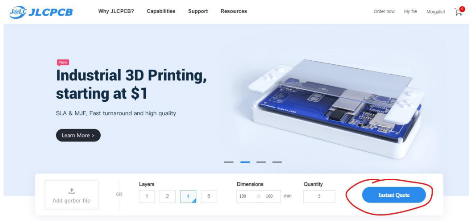
    After going to JLCPCB press Instant Quote button and upload your file.

  • 2
    Placing an order

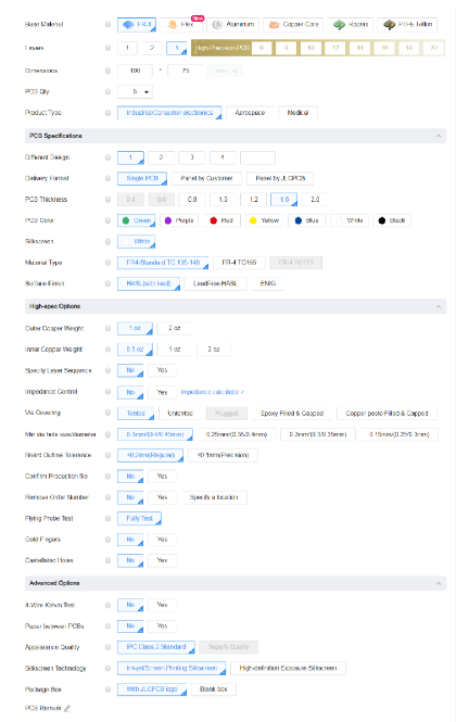
    After the board preview is shown, you have multiple optionsto adjust. Every option here i very clearly marked and described (when you hover over the question mark). 

    JLCPCB is also a sponsor of this whole project (not only this PCB, but all the PCBs in the car!). JLCPCB (Shenzhen JLC Electronics Co., Ltd.), is the largest PCB prototype enterprise in China and a high-tech manufacturer specializing in quick PCB prototype and small-batch PCB production. You can order a minimum of 5 PCBs for just $2 (2 layers), just enough to have a few test/spare ones.

View all instructions

Enjoy this project?

Share

Discussions

Similar Projects

Does this project spark your interest?

Become a member to follow this project and never miss any updates