Ted Yapo
-
Brightness / run-time trade-off
07/07/2017 at 01:03 • 0 commentsWhen you program the PIC on these boards, you can choose the number of current pulses the LED receives every 16ms:
;;;
;;; number of LED pulses per WDT timeout loop
;;;
  N_PULSES    equ   .7
LED_PULSE   macro
  variable  i
  i = 0
  while i < N_PULSES - 1
  movwf     LATA              ;start inductor ramp-up
  clrf      LATA              ;end inductor ramp-up
  nop                         ; 2 nops here - tuned for minimum current
  nop
  i += 1
  endw
  movwf     LATA              ;start inductor ramp-up
  clrf      LATA              ;end inductor ramp-up
  endm
This changes the brightness of the LED and the run-time for a given battery
I don't have a calibrated way to measure LED brightness, but I know the brightness is basically linear with the number of pulses. I routinely use one with 7 pulses (40 uA / 10 years on two lithium AA cells) for walking around in complete darkness.
I measured the current usage vs the number of LED pulses today:
N Pulses Current (uA) Lifetime (2AA LiFeS2 cells) 2 12.5 32 years (exceeds shelf life) 3 18.1 22 years 4 23.5 17 years 5 29.0 13.8 years 6 34.4 11.6 years 7 40.0 10 years More interesting than these specific points is the line fit to them, equating the current to the number of pulses:
Using this, we can estimate the number of pulses to program for a desired current drain by solving for N:
for I in uA.
To get the desired drain, we can divide the battery capacity by the desired run time:
For example, if we want a 1-year run-time from 2 AA LiFeS2 lithium cells with a 3.5 Ah capacity, we get I = 3.5/(365.25*24*1) = 400 uA. Using this we calculate N = 73.
Interestingly, when I program a board for 73 pulses, I measure a drain of around 350 uA, so the line fit isn't perfect. There is something interesting going on with many pulses - I suspect the 10uF capacitor is too small to hold up the voltage for that many pulses in a row, so the voltage sags and causes reduced current for later pulses in the burst. At least the equation gives you a decent starting point.
Incidentally, at this 350 uA drain, the LED will run for 30 seconds from a 3300uF (nominal) capacitor charged to 3.5V.
-
Assembly Instructions
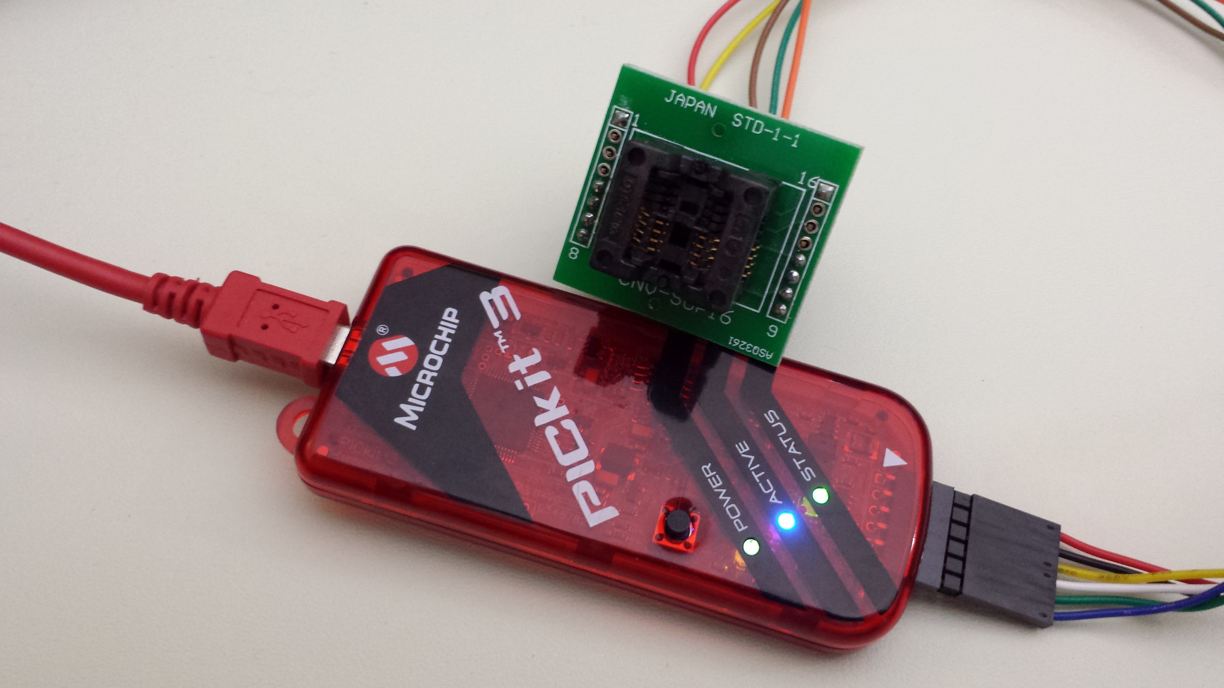
12/25/2016 at 17:57 • 0 commentsThere are four ways to program the SOIC microprocessor. First, you can have it programmed for you before you solder it on the board. Microchip and DigiKey both offer programming services, but the setup prices are high.
You can also use an SOIC socket. Here's one I've used in the past:
![]()
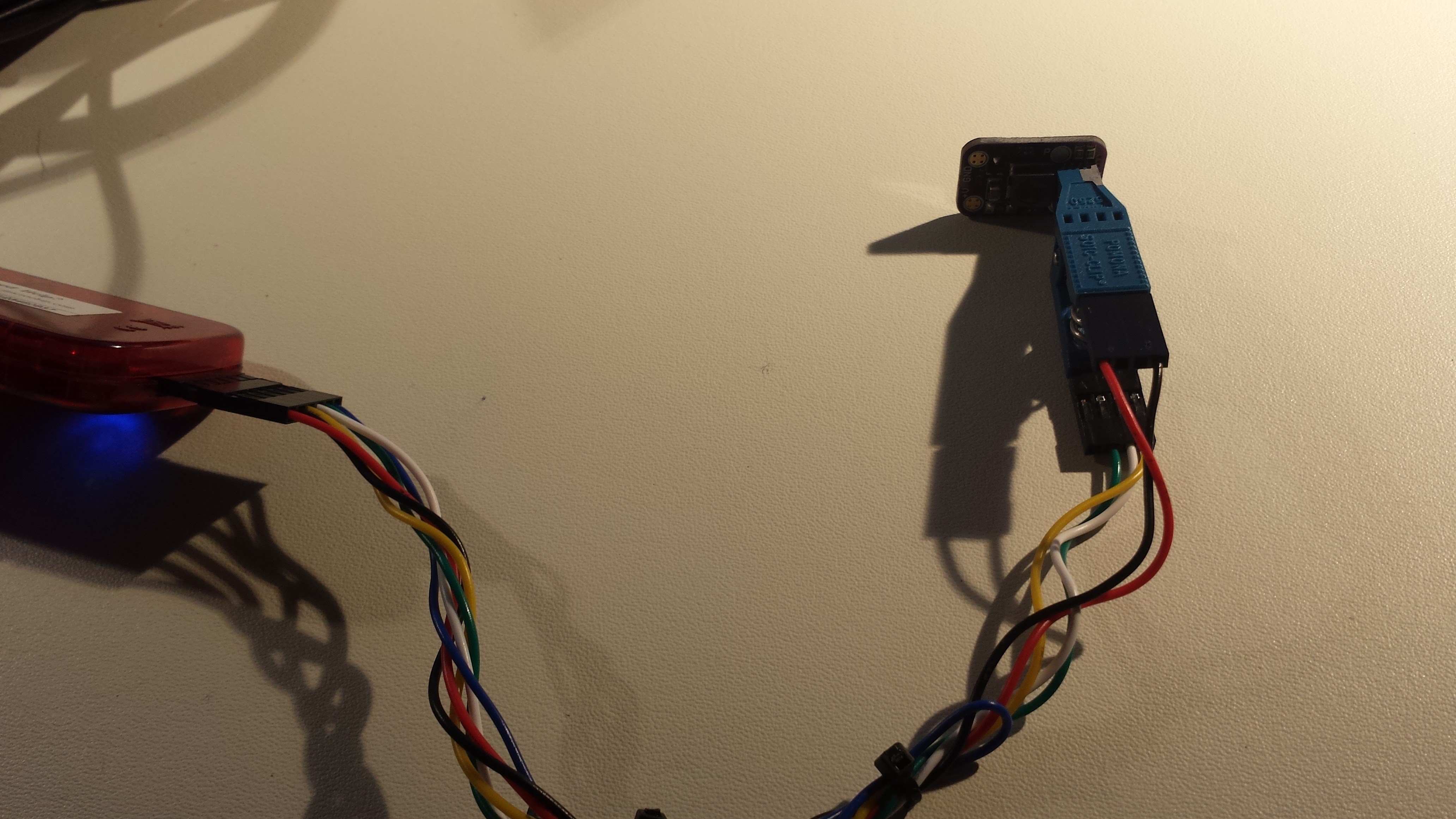
Even more convenient is an SOIC test clip. @LDX turned me on to these, and they're fantastic. Here's mine programming one of the flashlight boards:
![]()
Finally, you can temporarily solder wires onto the programming pads on the board. I've done this, too.
![]()
You may need to iterate a little on the programming. Due to the wide (30%) tolerance on the inductor, you might have to tune the PIC's internal oscillator frequency using the OSCTUNE register to obtain the proper current drain. Ideally, the current should be around 40 uA - this will 10 years of continuous service from the lithium AA batteries.
The final electrical connections are to solder the battery holder leads to the PCB. Leaving a little more wire than I did in this photo will make your life easier; there's room in the case for some extra wire, but leaving too little makes closing the case difficult.
![]()
To keep the batteries from rattling around in the case, I padded them with strips of electrical tape - but the tape is only applied to the batteries. Avoid wrapping the batteries and the holder together with tape: as the case ages, the batteries may need to shift slightly to maintain contact on the positive terminal. If they're fastened with tape, the springs may not be able to move the batteries.
A small piece of double-sided foam tape holds the printed battery compartment cap to the battery case. Once this is in place, you can assemble the rest of the case.
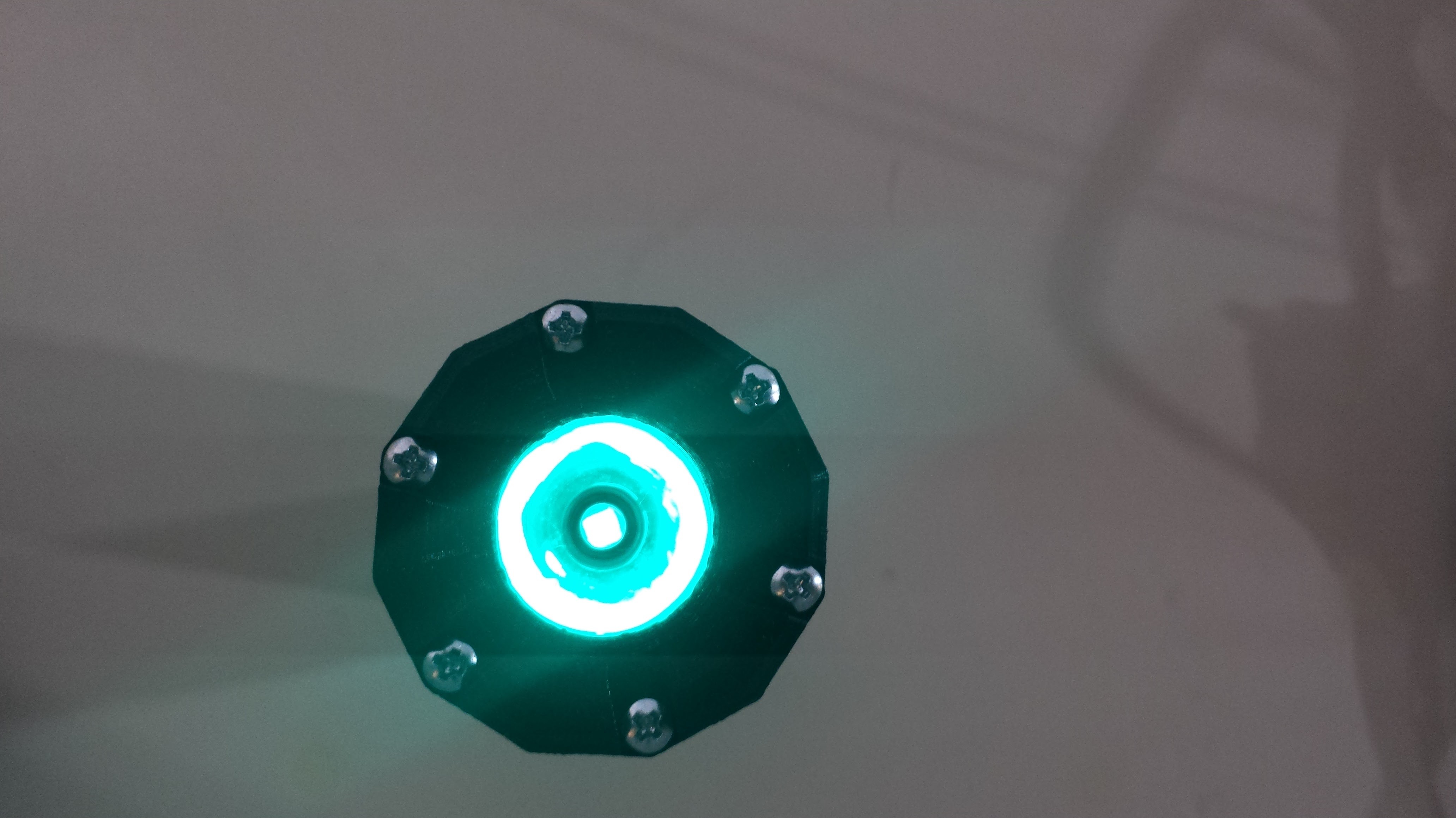
Here's what it should look like when you're done:
![]()
The light is surprisingly bright when your eyes are fully dark adapted. It's perfect for a bedside or nighttime task light; Unless you look at it directly, it doesn't seem to degrade your darkness adaptation very much.
-
Printed Case
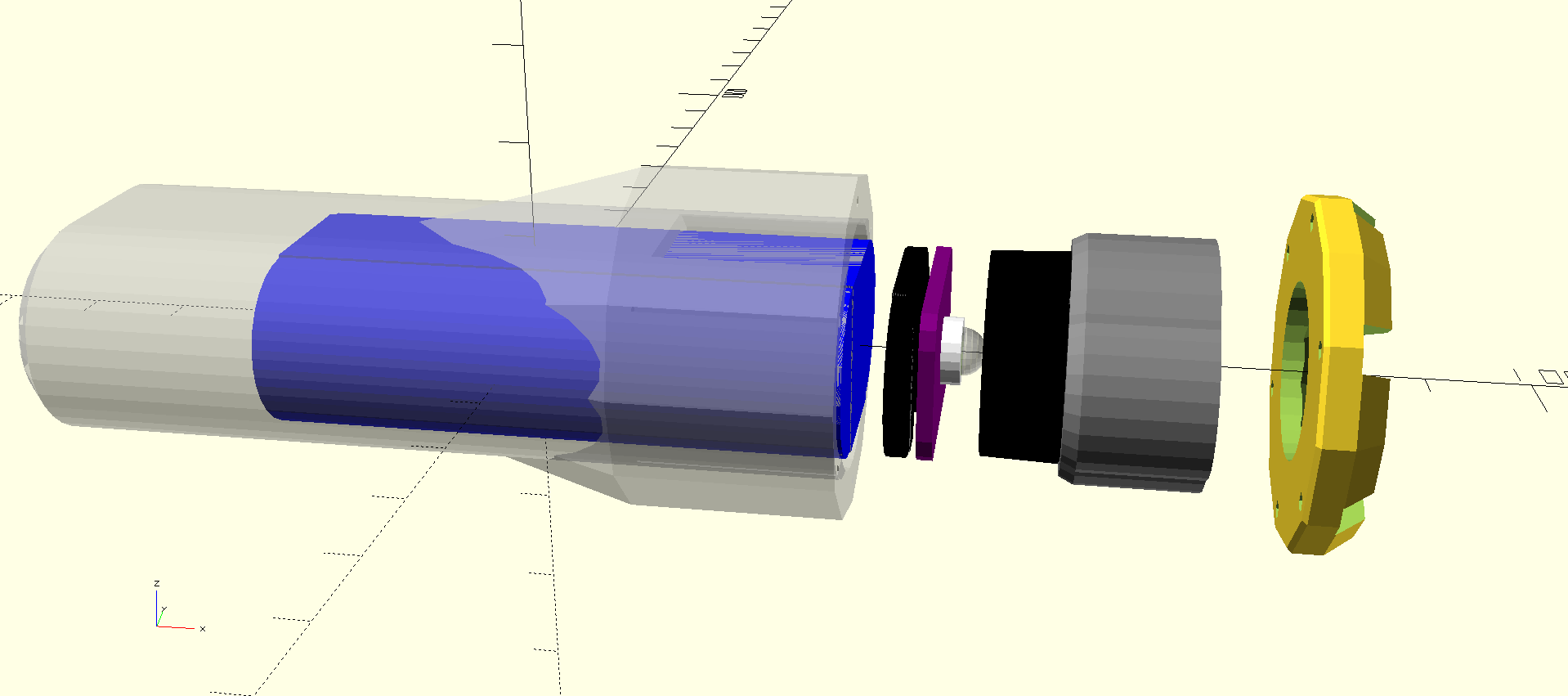
12/25/2016 at 17:57 • 0 commentsI designed the case in OpenSCAD. It consists of four printed pieces: the main body / battery compartment, a battery compartment cap, a lens holder, and the front bezel. Completing the assembly are the battery holder (purchased), the PCB, and the lens:
![]()
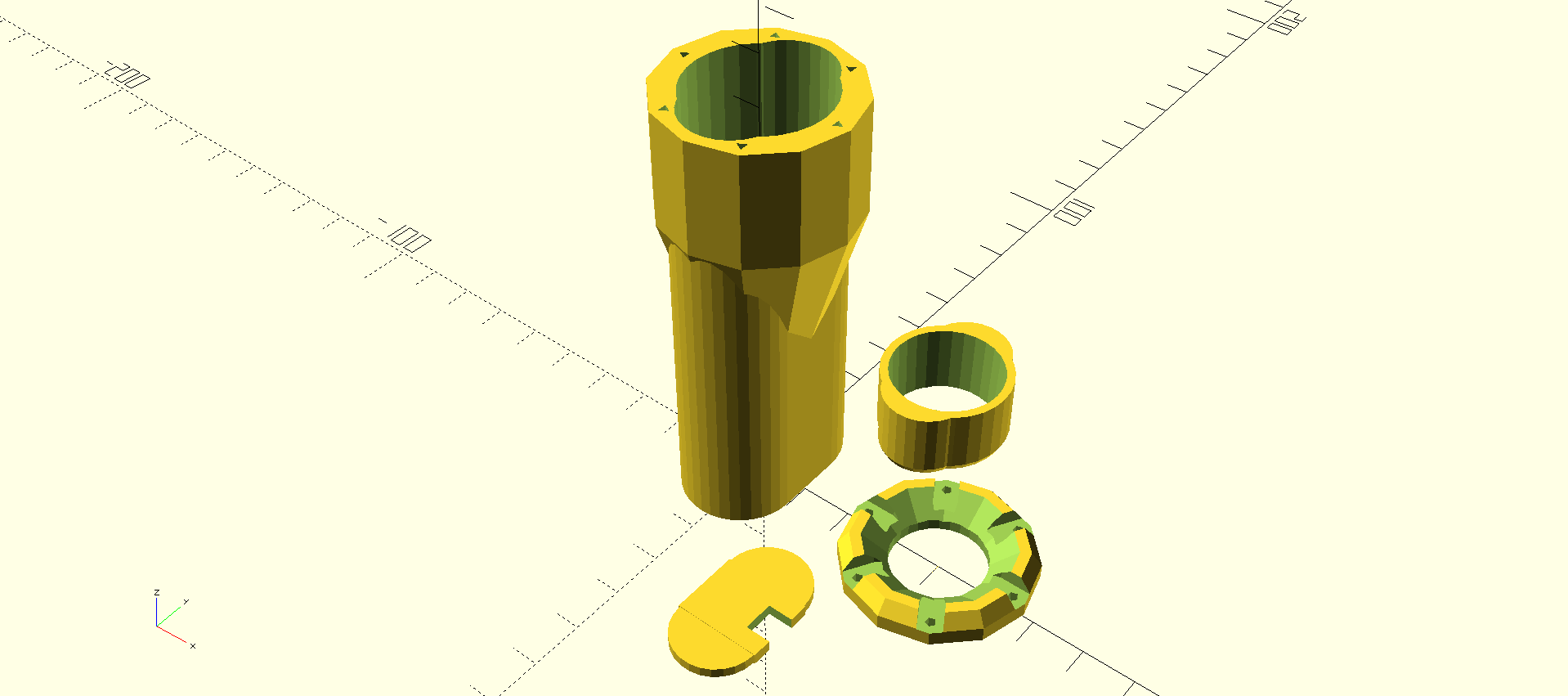
The OpenSCAD file has a layout variable that produces an exploded view like above, or a printing layout shown here:
![]()
I've printed these parts in both normal PLA and polymax. Normal PLA is too brittle for a flashlight like this that could easily get dropped. ABS would be better, but I'm not set up to print ABS at the moment. This was the first time I have used polymax, which is a kind of enhanced PLA - it prints like PLA (actually far better in my opinion), and is supposed to be more resilient than even ABS. After a few days working with it, I'm completely sold on the concept. It has printed better than any ABS or PLA I've used before, and seems quite strong. It's also much better for minor touch-ups like drilling out holes to the proper diameter than normal PLA. If the polymax were a little cheaper, I'd switch over entirely. With the cost being about 2x normal PLA, I might just use polymax where necessary for strength or for final copies of finished projects.
The screw holes in the bezel and case were designed to use 2-28 3/8" thread-rolling screws, which work very well in the polymax. The holes are deliberately undersized for printing, so that they can be cleanly drilled afterwards. I cleaned out the bezel holes with a succession of 1/16", 3/32", and 5/64" bits, which let the screws fit through without binding. The case holes, which the screws will self-tap, were cleared out with the 1/16", then the mouth of each was widened just slightly with the 3/32" to allow the screw to start.
I printed the first prototype at a 346 micron layer height in normal PLA. With these parameters, the resulting parts has a rough fit. The final versions (two so far) have been printed with 127 micron layers with polymax filament - these parts fit much better.
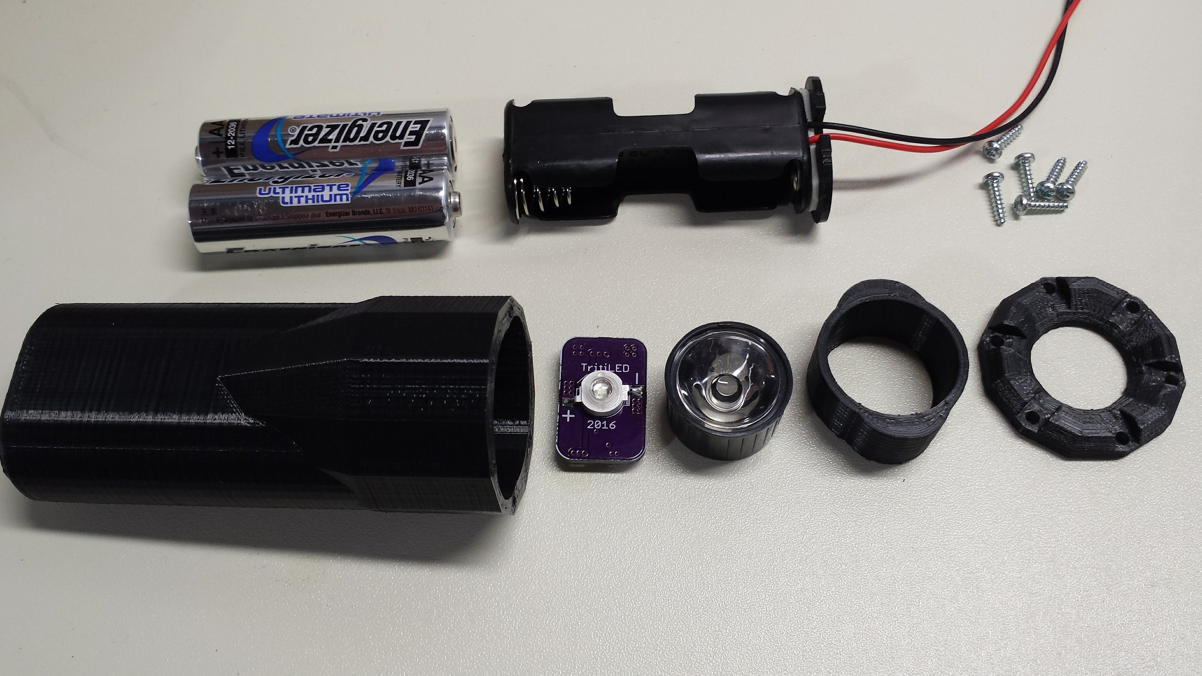
Here are all the components roughly lined up. The battery compartment case is already attached to the end of the battery holder with a piece of double-stick foam tape.
![]()
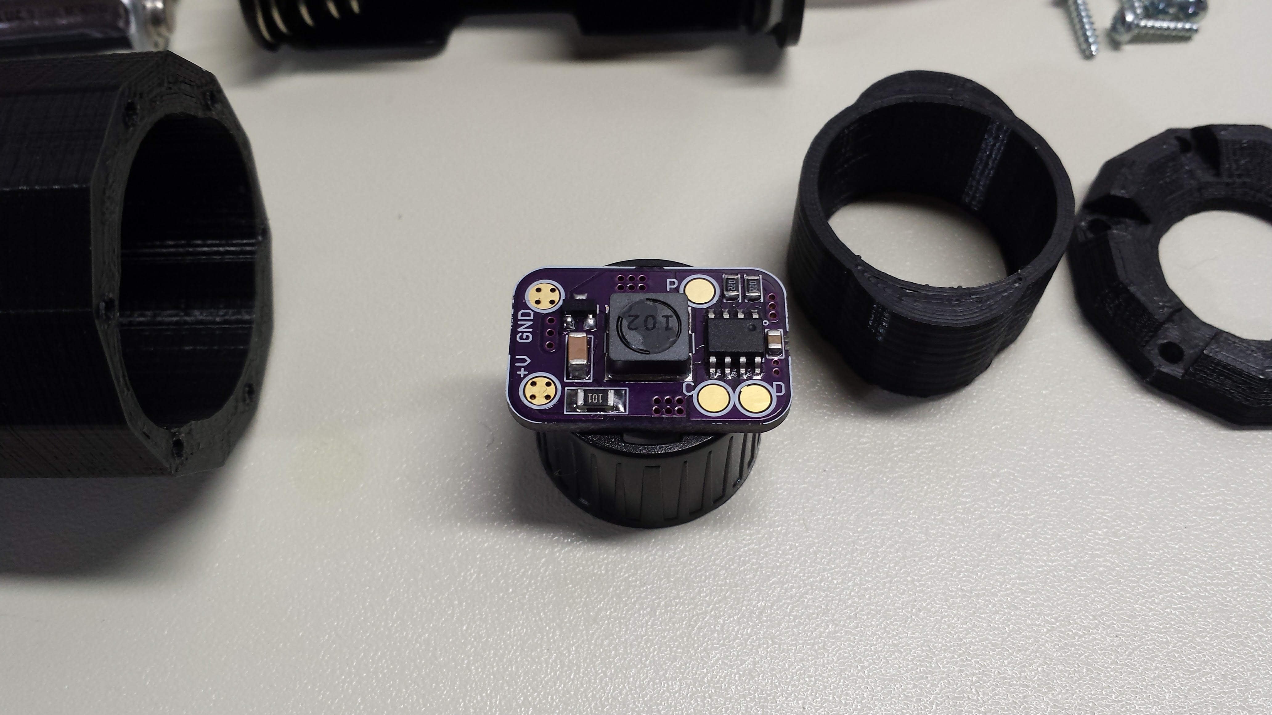
Here's the detail of the PCB mounting. The lens is designed to press-fit on the LED case. This holds the PCB in the flashlight.
![]()
-
PIC12LF1571 Code
12/25/2016 at 17:56 • 0 commentsThe PIC12LF1571 is programmed in assembly. The code wakes up every 16ms using the watchdog timer - this is a frequency of 62.5 Hz, above the flicker-fusion rate, so you don't notice the blinking unless the light is moving. Each time the code wakes, it pulses the LED 6 times. The PIC oscillator is set to 500 kHz to save power. The desired 8 us current pulse to the inductor is one instruction cycle long at this frequency.
A few techniques have been used in the code to enhance reliability; this code is supposed to wake up about 20 billion times over the life of the battery. First, all unused locations in the instruction memory are filled with the "reset" instruction. If the program counter gets screwed up and points to a random place, it will just reset the code and everything will start clean again. The code itself actually issues a reset instruction every 256 times it wakes - this periodically re-initializes any register settings that may have become corrupted. It might be safer to reset every time, but this adds a lot of overhead, resulting in excessive current drain and reduced efficiency.
The OSCTUNE register is used to adjust the current drain of the assembled PCB. Since the inductor has a 30% tolerance, the software may require tweaking to obtain the desired battery life. Even though the OSCTUNE register only allows +/-12% adjustment, I have so far always been able to tune the current to the desired value (40 uA). If an inductor was discovered that didn't allow this, the number of LED pulses could be changed from 6 to either 5 or 7 to roughly tune the power, then the OSCTUNE adjustment could be again used for fine tuning.
Here is the code listing. Of course, if you want the code, you should get it from the GitHub repo.
;;; ;;; ten_year_lamp.asm : ;;; PIC12LF1571 code for (2x) LiFeS2 AA-powered LED glow marker ;;; ;;; 20161106 TCY LIST P=12LF1571 #include <p12lf1571.inc> ERRORLEVEL -302 ERRORLEVEL -305 ERRORLEVEL -207 ;;; ;;; OSCTUNE_VAL: set to fine-tune current draw for compensating for ;;; component tolerances ; OSCTUNE_VAL equ 0 OSCTUNE_VAL equ b'00100000' ; OSCTUNE_VAL equ b'00011111' ;;; ;;; number of LED pulses per WDT timeout loop ;;; N_PULSES equ 6 LED_PULSE macro variable i i = 0 while i < N_PULSES - 1 movwf LATA ;start inductor ramp-up clrf LATA ;end inductor ramp-up nop ; 2 nops here - tuned for minimum current nop i += 1 endw movwf LATA ;start inductor ramp-up clrf LATA ;end inductor ramp-up endm ;;; ;;; I/O pin configuration ;;; GATE_DRIVE_A equ 4 GATE_DRIVE_B equ 5 __CONFIG _CONFIG1, _FOSC_INTOSC & _WDTE_ON & _PWRTE_OFF & _MCLRE_OFF & _CP_OFF & _BOREN_OFF & _CLKOUTEN_OFF __CONFIG _CONFIG2, _WRT_OFF & _PLLEN_OFF & _STVREN_OFF & _BORV_HI & _LPBOREN_OFF & _LVP_ON ;;; ;;; variables in Common RAM (accessable from all banks) ;;; CBLOCK 0x70 reset_counter ENDC ORG 0 RESET_VEC: nop nop nop nop INTERRUPT_VEC: BANKSEL OSCCON movlw b'00111011' ; 500 kHz MF osc movwf OSCCON BANKSEL OSCTUNE movlw OSCTUNE_VAL movwf OSCTUNE movlw .255 movwf reset_counter BANKSEL ANSELA movlw b'00000000' ; all digital I/O movwf ANSELA BANKSEL LATA clrf LATA BANKSEL TRISA clrf TRISA ; set all lines as outputs BANKSEL WDTCON movlw b'00001001' ; WDT 16ms timeout movwf WDTCON BANKSEL LATA movlw (1 << GATE_DRIVE_A) | (1 << GATE_DRIVE_B) MAIN_LOOP: LED_PULSE sleep decfsz reset_counter goto MAIN_LOOP reset ;; fill remainder of program memory with reset instructions fill (reset), 0x0400-$ END -
Circuit Design / LED Driver Board
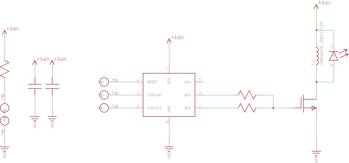
12/25/2016 at 17:56 • 2 commentsHere's the circuit used to drive the LED. A PIC12LF1571 periodically wakes to pulse the gate of an N-channel MOSFET. The MOSFET allows current to build through a 1 mH inductor; once the MOSFET shuts off, the inductor discharges through the LED to create the light pulse. There are more details about this circuit in #TritiLED.
![]()
A 100-ohm resistor is added in series with the battery for fault protection - if the PIC becomes stuck for some reason, the MOSFET shorting the inductor across the supply might drain the battery, but the 100-ohm resistor will hold the current and dissipation to a safe level. Likewise, the two resistors in the gate drive circuit (22 ohm each) keep the PIC outputs from "fighting" if the software is somehow corrupted and the two outputs assume different states.
Optimal Current Drive
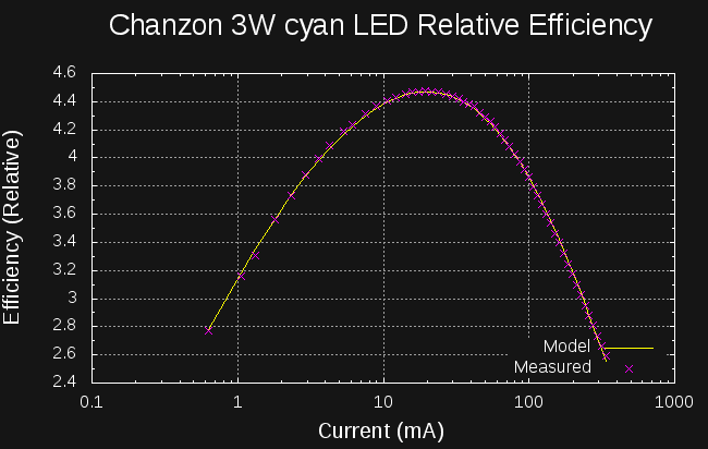
I measured the relative efficiency of the Chanzon 3W (45x45 mil chip) cyan LED with the #Automated LED/Laser Diode Analysis and Modeling system. Here's the efficiency for DC drive conditions:
![]()
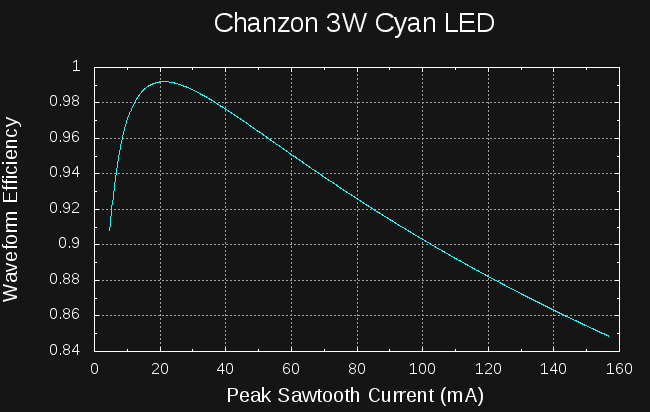
If you were driving this LED with DC, you would see peak efficiency at around 20 mA. For the flashlight design, the average battery drain is about 40 uA. At this DC current, the efficiency of the LED is abysmal, so it is much better to drive with higher-current pulses at a low duty cycle. Since the circuit shown above uses roughly triangular-shaped pulses, I wrote some code to analyze the efficiency based on the peak current in a sawtooth waveform:
![]()
You can see that driving this LED with a sawtooth waveform of anywhere between 10 and 35 mA will achieve at least 98% of the LEDs peak efficiency. Depending on the particular inductor (the part I'm using has a 30% tolerance), the actual current will vary, but should always be in this range. More details about this analysis can be found in #TritiLED.
The software is tuned to produce an average current drain of about 40 uA at 3.6V. Lightly loaded, the lithium AA batteries will maintain about 3.6 V for most of their life. Based on a 3500 mAh capacity, a 40 uA drain will deplete the batteries in a little over 10 years. Since the battery voltage will drop somewhat at the end, resulting in a reduced current drain, you might get a little longer than this (at reduced brightness). These lithium AA's have a shelf-life of 20 years, so self-discharge over the decade of use will not be an issue.
The code blinks the LED six times every 16 ms, so over a 10-year span, the LED will blink about 118 billion times. Your heart will beat about three billion times total - unless you can come up with the coolest hack ever :-)
Bill of Materials
A more detailed BOM is in the GitHub repo, but here are the electrical/optical components listed out
- (1) PIC12LF1571 8-SOIC DigiKey part # PIC12LF1571-I/SN-ND $0.57 each
- (1) Bourns SRR6028-102Y 1mH inductor. DigiKey part # SRR6028-102YCT-ND $0.68 each
- (1) 10uF 25V 1206 X7R MLCC capacitor. DigiKey part # 1276-1804-1-ND $0.24 each
- (1) 0.1uF 25V 0805 X7R MLCC capacitor. DigiKey part #311-1141-1-ND $0.10 each
- (1) 100 ohm 1206 resistor. DigiKey part # 311-100FRCT-ND $0.10 each
- (2) 22 ohm 0805 resistor. DigiKey part # 311-22.0CRCT-ND $0.10 each
- (1) ZXMN3B01FTA N-channel SOT23 MOSFET. DigiKey part # ZXMN3B01FCT-ND $0.52 each
- (1) AA Battery holder w/leads. Digikey part # BC22AAW-ND $0.99 each
- (1) CHANZON 3W Cyan LED. Find them on Amazon : $9.52/10, AliExpress : $7.90/10, or Ebay (various sellers/prices)
- (2) Energizer L91 AA Ultimate Lithium cells. DigiKey Part # N602-ND $3.61 each.
Much cheaper elsewhere. For example, you can get 8 of them for $12 on Amazon. - (1) Lens for the 3W LED. Again, you can find these on AliExpress, Amazon, or Ebay. They will fit 1W, 3W, or 5W LEDs. Here's an example listing for them on Ebay. I have an assortment of different ones - I liked the beam from 20 and 30-degree lenses best, but ended up with the 20-degree one since it has a bright inner beam surrounded by a wider, less bright cone. I'll have to take some pictures of it.
I didn't add it all up, but if you build more than one of them, it's obviously much cheaper. The 0805 resistors, for example, are $0.10 for one, but $0.19 for 10. Since you probably need to buy 10 of the LEDs and lenses anyway, you might as well build a bunch and save. I guess this is where kits or group buys bring the price down :-)
PCB Design
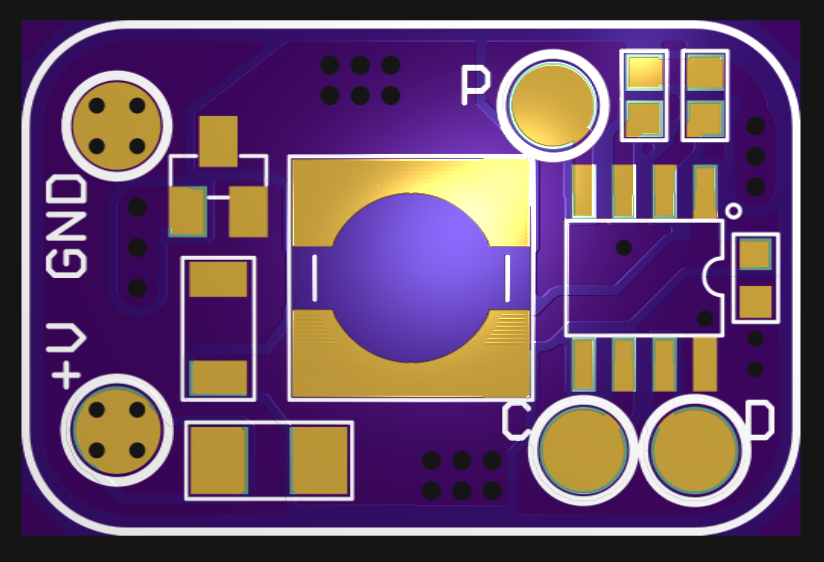
Here are the PCB's front and back. All the components except the LED mount on the back of the board - they can be reflow soldered, then the LED can be hand-soldered on the front.
![]()
![]()
The boards can be ordered from OSH Park. Cost is $3.05 for 3 boards. The gerber previewing software I use doesn't round the corners on these renderings, but as you can see below, the board fab will. The battery connections are intended to be soldered to the +V and GND pads. Vias are provided in the pads for strain relief, preventing the pads from lifting off the boards with the wires. Pads are also provided for ICSP programming of the PIC. Here's the key to my terse labeling:
- P: MCLR/VPP
- D: ICSPDAT
- C: ICSPCLK
I didn't make a pogo-pin jig for this board. You can temporarily solder wires to the programming pads if necessary - more details in the assembly log.
The board is held in place by the LED package. The lens for the LED is designed to press-fit onto the LED itself. This holds the board in place the flashlight:
![]()