Analog Lorenz Attractor Computer
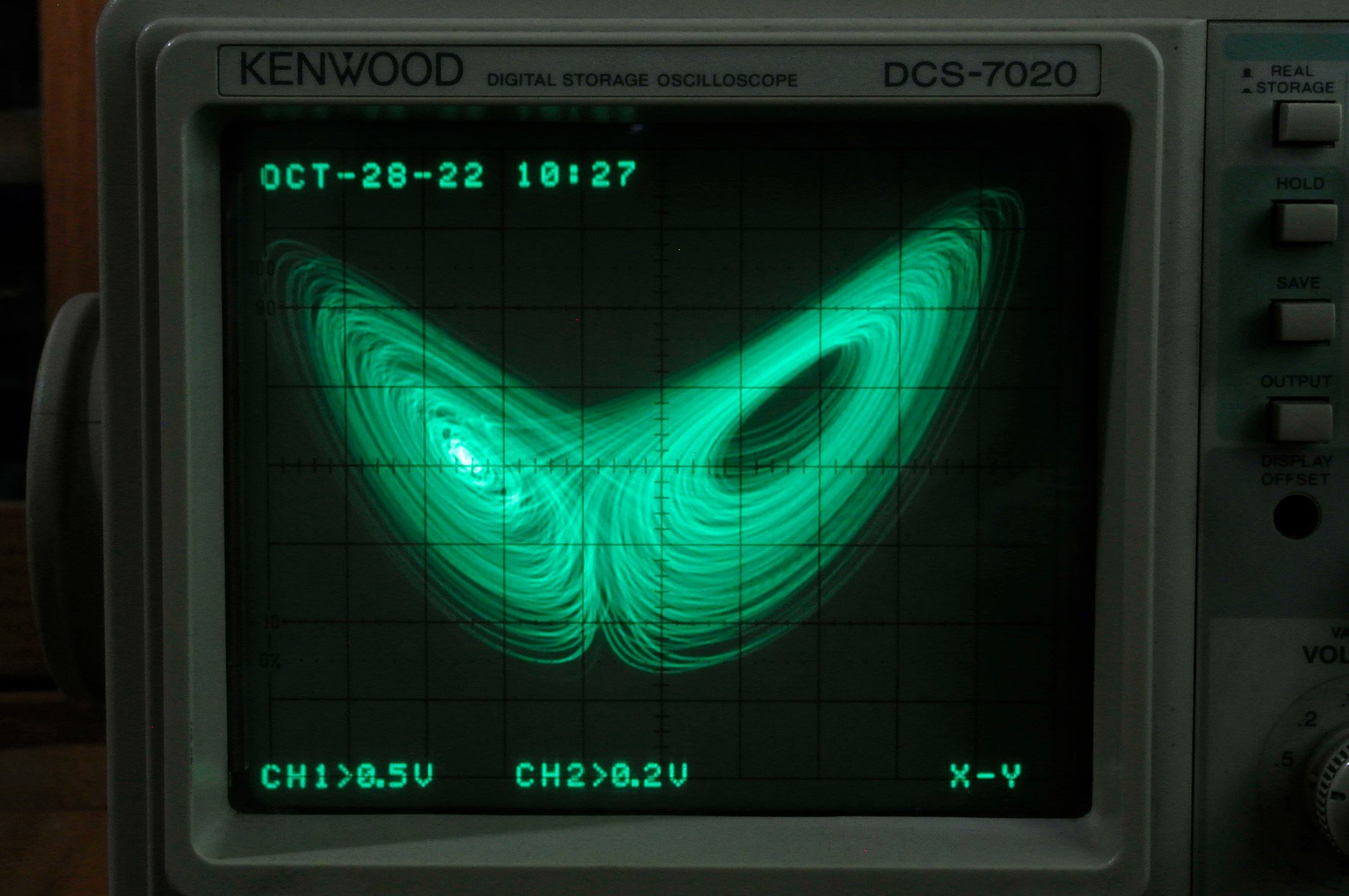
1. The Origin of Analog Computer
One of the main purposes of analog circuits is to solve mathematical problems, such as building a circuit corresponding to a nonlinear differential equation and analyzing the phase plane characteristics of it by observing its output voltage with an oscilloscope or analog plotter. I will take a famous nonlinear differential equation, the Lorenz Attractor, as an example, and show the whole process of solving it with an analog circuit.
2.Lorenz Attractor
The Lorentz attractor is a set of equations describing the dynamical behavior of the atmosphere, which reveals the chaotic phenomena contained in meteorological changes and is known as the "butterfly effect". The Lorentz attractor consists of three nonlinear differential equations:

Among them, sigma, b and r are the three constants that determine the characteristics of the system, commonly taken as sigma = 10, r = 28 and b = 8/3. Before building the analog circuit, we can simulate it with software to understand some basic characteristics (sounds a bit strange~~). The software used is Octave, and the Lorentz attractor function is declared in lorenz.m, where x is a three-dimensional vector set, and x(1), x(2), and x(3) represent x, y, and z in the original set of equations, respectively, while a scale factor k is added for further usage.
% Lorenz.m

function dx = lorenz(x, s, r, b, k)
    dx = zeros(3, 1);
    dx(1) = k*(s*(x(2) - x(1)));
    dx(2) = k*(-x(1)*x(3) + r*x(1) - x(2));
    dx(3) = k*(x(1)*x(2) - b*x(3));
end
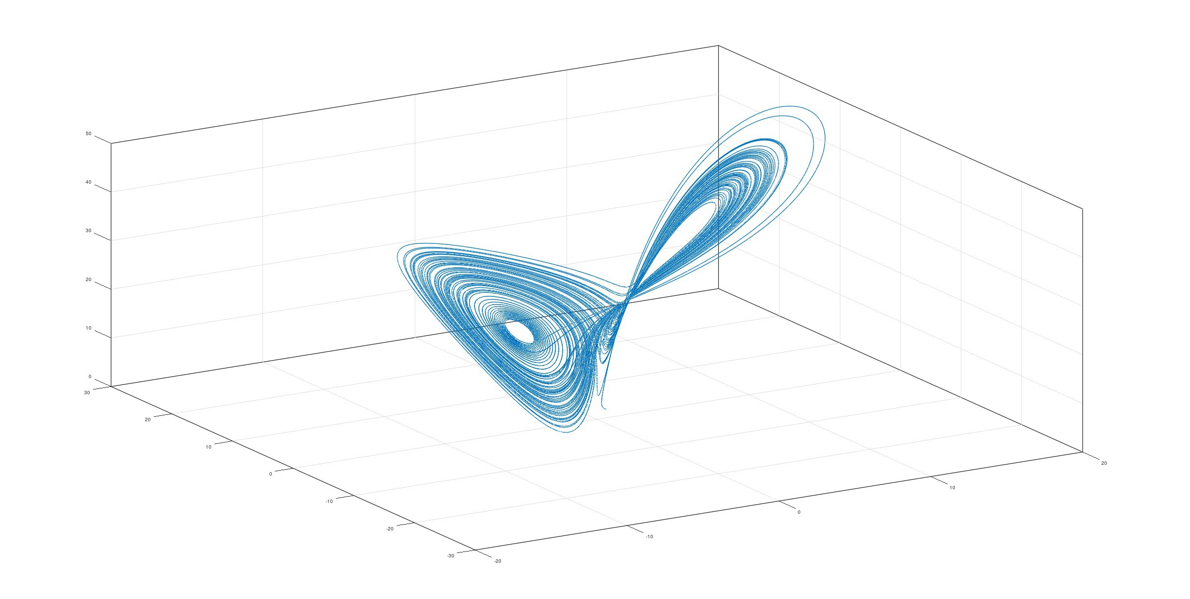
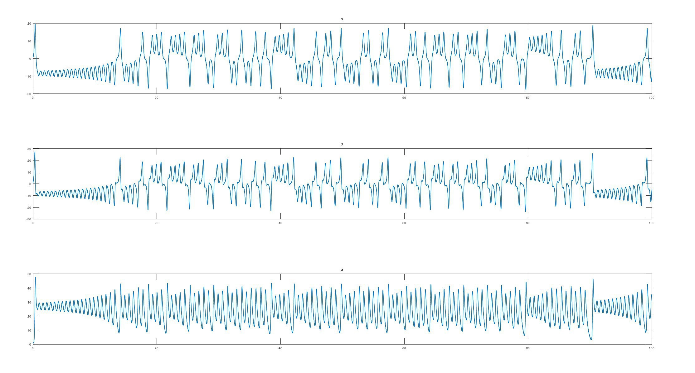
The lorenz function is called in test.m and solved numerically. Here the fourth-order Runge-Kutta method is used and the initial values of the equations are set to (1, 1, 1). Finally, the trace of x is presented in three and one dimensions, respectively:
% test.m

clc; clear all;

dt = 1e-3;
t = 0 : dt : 100 - dt;

s = 10;
r = 28;
b = 8/3;
k = 1;

x = zeros(3, length(t));
x(:, 1) = [1; 1; 1];

for tn = 1 : 1 : length(t) - 1
    k1 = lorenz(x(:, tn),           s, r, b, k);
    k2 = lorenz(x(:, tn) + dt*k1/2, s, r, b, k);
    k3 = lorenz(x(:, tn) + dt*k2/2, s, r, b, k);
    k4 = lorenz(x(:, tn) + dt*k3,   s, r, b, k);
    x(:, tn + 1) = x(:, tn) + dt/6*(k1 + 2*k2 + 2*k3 + k4);
end

figure;
plot3(x(1, :), x(2, :), x(3, :), '-'); box on; grid on; drawnow;

figure;
subplot(3, 1, 1); plot(t, x(1, :)); title("x");
subplot(3, 1, 2); plot(t, x(2, :)); title("y");
subplot(3, 1, 3); plot(t, x(3, :)); title("z");
The simulation results are shown in the following figure:
3.How to Design an Analog Computer
How can this set of equations be "translated" into an analog circuit? This is illustrated by a diagram:
In analog circuits, the most convenient circuits used to perform calculations are those designed based on inverting amplifiers, which are simpler in form than non-inverting amplifiers and also avoid distortion and noise from common-mode operation, which was particularly important in the early years of op-amp development.
In the first step, determine the implementation of the various operations as:
- Integral: use the inverting integrator circuit, but temporarily discard the resistor, which is equivalent to integrating the input current and multiplying by -1.
- Multiplying by -1: use the inverting amplifier and set the two resistors with the same value.
- Addition: use current summation instead of voltage, so the form is simpler.
- Multiplying by a constant k: use a resistor with a resistance of 1/k, the voltage across it is converted into a current and output as a result.
- Multiplication: implemented using a dedicated voltage multiplier.
In the second step, the integrator is cascaded with the inverting amplifier, and the output of the integrator is set to -x, the output of the inverter is x, and the input of the integrator is dx/dt. Then calculate the equivalence of dx/dt and input it at dx/dt. The x and -x signals needed in the operation are obtained from the above output. y and z signals are obtained in the same way. The signal flow diagram can be drawn in this...
Read more » CheeenNPP

 Mitsuru Yamada
 Grant Giesbrecht
Could you make a short video of oscilloscope screen?