Remove the back by unscrewing the 7 Philips screws (be sure the device is unplugged for safety.
Before implementing the above changes, I chose to rewire key elements for safety
Make sure the hot wire goes to the base of the bulb. In my case the hot wire went from the thin prong to the switch to the fuse and then to the exterior of the bulb (via the power meter) rather than to the base of the bulb -- this should be reversed -- see later for how it is all wired
Replace the super thin, bare metal wire that daisy chains the bulbs together with insulated 18 gauge stranded wire -- it was super scary to me seeing the loose thin wire (see picture above). Hard to believe that wire wouldn't be near glowing if you used this anywhere near the 5A fuse value.
2
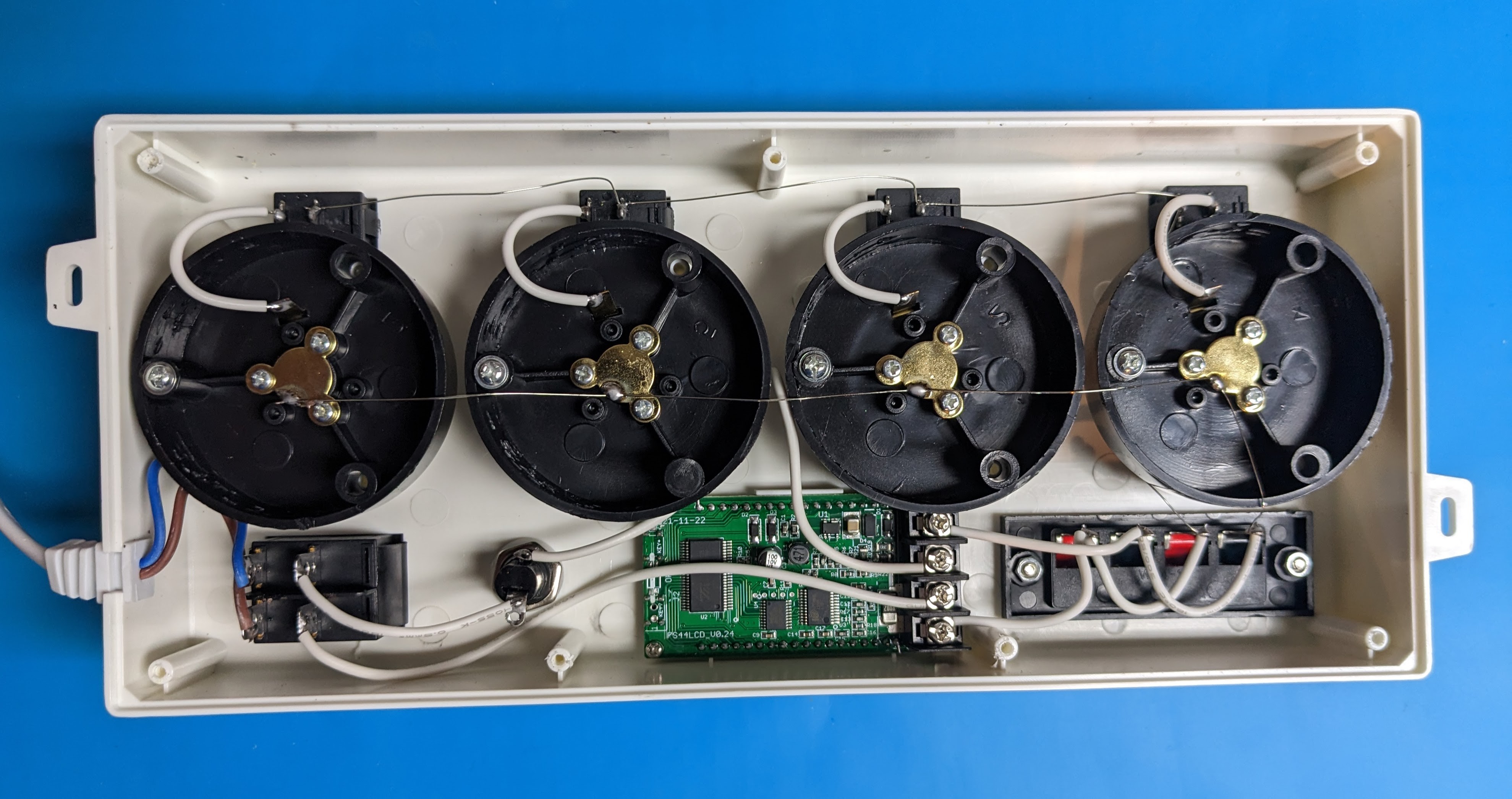
Re-Wire Loads in *Series* with the 4 parallel-wired Bulbs
Solder/desolder relevant wires so that the wiring path runs as follows
Hot wire from input Power Cord -> DPDT Switch (top/outer contact)
DPDT Switch (top/inner contact) -> Fuse
Fuse -> 2nd Innermost screw on meter PCB
Innermost screw on meter PCB -> 4-bases of the bulbs (all wired in parallel with 16 gauge wire as above)
4 sides of the bulbs (all wired in parallel with 16 gauge wire as above) -> one of the 2 connected Red terminals on the wiring block
One of the 2 connected Black terminals on the wiring block -> Outermost screw on meter PCB
2nd Outermost screw on meter PCB -> DPDT Switch (bottom/inner contact)
DPDT (bottom/outer contact) -> Neutral wire from input Power Cord
3
(Optionally) Add "Test" button
Add a momentary NO (normally open) pushbutton switch in parallel with the load. I used a 6A pushbutton switch with a 5/8" round base
Drill a 5/8" hole in the front side of the case next and centered on the terminal block. A step-drill works well.
Secure the button to the case with lock washer and nut as provided
Use short jumper wires to connect one of the pushbutton contacts to one of the Red wiring block terminals and to connect the other contact to one of the Black wiring block terminal.
Note that pushing the button shorts the load and should light any bulb that is switched on.
4
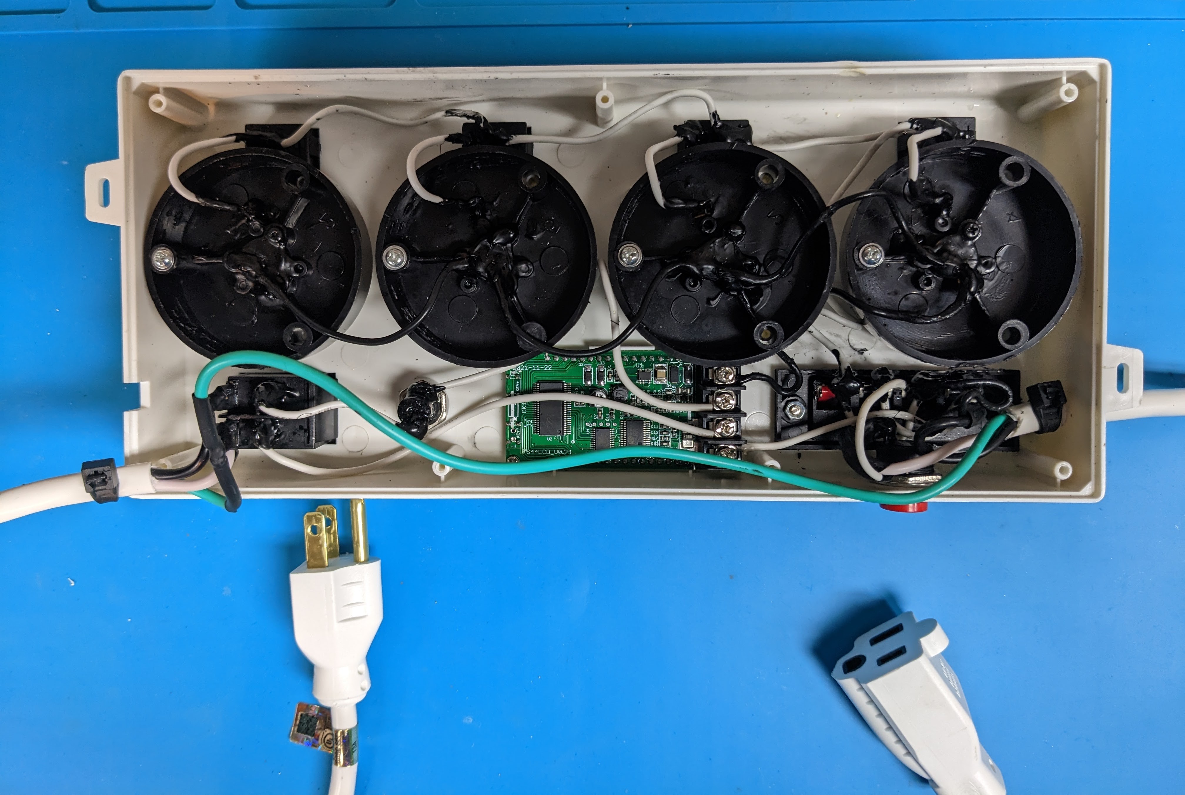
(Optionally) Add a grounded AC socket and replace the existing input plug with a grounded plug.
I bought a cheap 8-foot 16/3 (16 guage grounded) extension cord from the Big Box Store and cut it, leaving 6 feet for the plug-end and 2 feet for the socket-end.
De-solder the input wires to the DPDT switch and replace & re-solder with the 6 foot plug-end of the cord (paying attention to hot and neutral polarity). The plug end of the cord should fit through the existing square hole though it may need to be enlarged or the tab removed from the back cover to accommodate the likely larger cord diameter
Drill a hole for the 2 foot socket-end of the cord in the side end of the case (near the wiring block) and connect the hot and neutral wires in parallel to the load. i.e., black (hot wire) to one of the Red contacts and white (neutral) wire to one of the Black contacts
Connect the green wire from the plug-end directly to the green wire on the socket-end. There is nothing to ground internally in the case
Tighten and trim a zip tie around the inside end of both the plug and socket cable ends to add strain relief, preventing the cords from being pulled out.
5
Check and clean-up wiring
Where practical, use heat shrink tubing to insulate connectors and/or liquid electrical tape. For safety sake, I was pretty careful to cover every exposed high-voltage contact
Check your wiring to make sure it is all done correctly, that there are no exposed connectors, and that no wires are crimped
6
Replace back cover
Screw back in the 7 screws making sure that no wires are pinched
7
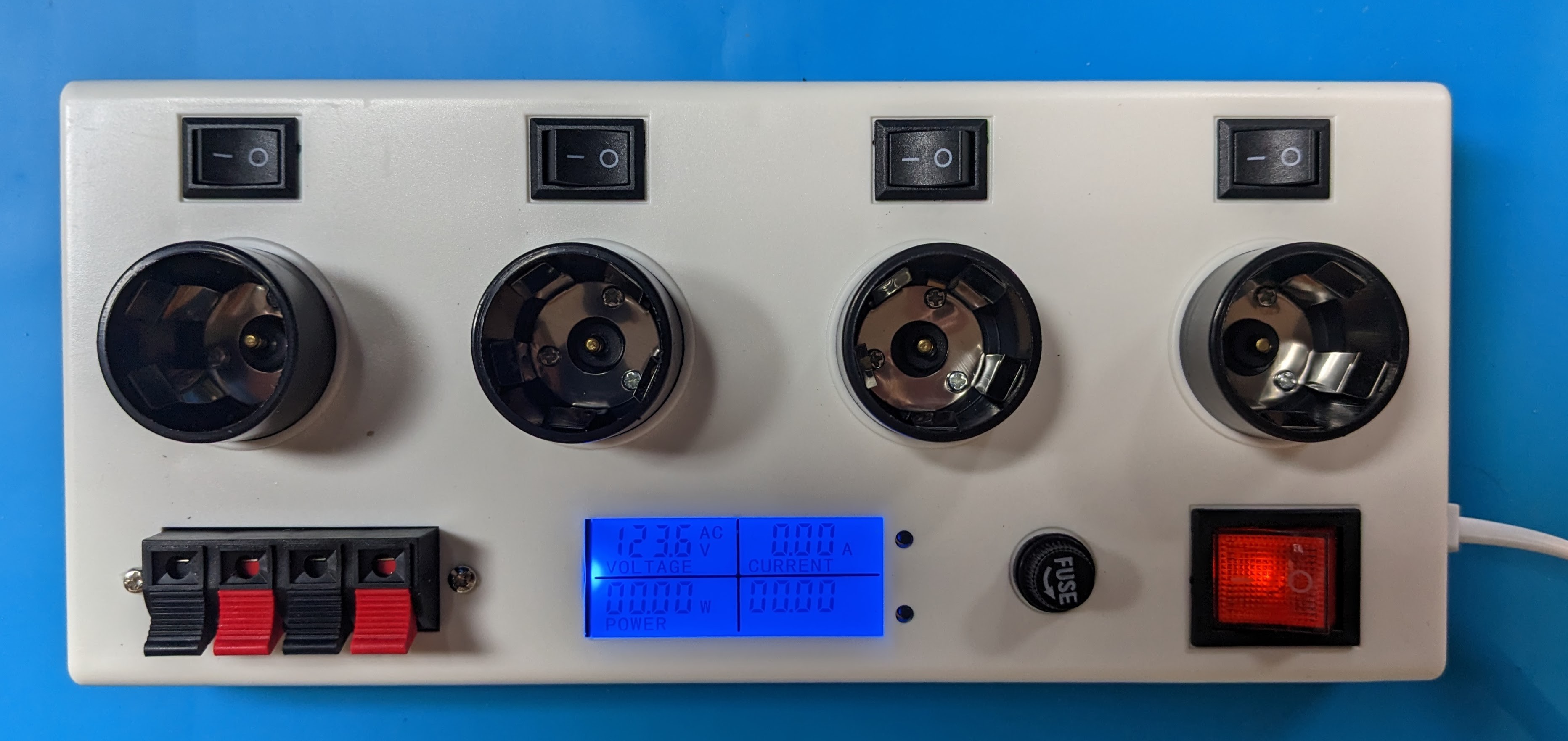
(Optionally) Add labels to highlight key functionality
Discussions
Become a Hackaday.io Member
Create an account to leave a comment. Already have an account? Log In.