Adam Oakley
-
Code Rewrite
01/09/2017 at 01:49 • 0 commentsAfter running into some bugs with the old software, I became fed up with the messy code and decided to start fresh. The new code is more organized and the documentation is much more complete.
The user interface is somewhat simpler now as well. Instead of selecting battery chemistry and number of cells, the user just enters the desired cutoff voltage. The code for this is simpler and it also makes the load tester more useful. For example, you could discharge lithium cells to about 70% charge for long term storage by entering the appropriate cutoff voltage. You could also test supercapacitors down to 0V.
You can find the source code by following the github link on the project page
-
I ain't dead yet!
11/29/2015 at 00:44 • 0 commentsAfter putting this project on the shelf for months, I've put some work in and the project is in a reasonably finished state. There's more that I want to do with the software so I may work on that and post updates. I have posted the current source code and uploaded a few pictures. The source code is not pretty. It needs better documentation, but it does the job.
As for what work I have done, most of my effort has been put towards 3D printing the case for this project. The case was a big headache. I spent a decent chunk of time modeling the case in Autodesk Inventor and I was pretty happy with the design. I designed some 3D printed buttons that make use of standard tactile switches. These buttons feel very satisfying and I like that the parts are very cheap.
Albert and I ran into quite a few problems actually printing the case out. The case is fairly long because it has to hold all the circuitry and a big heatsink. The long case is very difficult for us to print because with ABS plastic on a print this large we get warping issues. Aside from that Albert's printer broke before we could print out the project case properly. The printer had all sorts of feeding issues, from the nozzle getting clogged and also from the extruder failing midway through prints.
Albert put a lot of effort into repairing his printer and now it's working again, but not fully. We managed to print out my case with some minor warping. The warping made it difficult to fit things in properly but I managed to make it work. I soldered everything together and closed up the case.
As it happens right when I finished assembling the load tester, my home's alarm system began complaining about a low battery. I removed the sealed lead acid battery and tested it with my load tester. The tester worked great, and reported that the alarm battery had a remaining capacity of 93mAh. The battery was originally 4.5Ah so it's clearly worn out now and needs to be replaced.
-
It works!
04/22/2015 at 03:03 • 0 commentsI'm getting close to finishing this project. I decided not to add a charger IC, as it would be very difficult to be able to charge all the different types of batteries I want to support. Right now I can test LiPo/LiIon, LiFe and Lead Acid batteries. I can basically test any battery under 14V, so I'll be adding a few more types to the software in the near future.
As for software, I have an LCD connected to the arduino as well as a few pushbuttons. I've implemented a fairly simple interface on the LCD, which allows you to pick your battery type and test current before beginning the test. You can run the test without a PC, but if you connect a PC the arduino will output CSV format data over the serial interface which you can record.
The load testing works pretty well. Due to the limited resolution of the PWM output from the arduino, I can only set the load current within about 10mA of my target, which should be fine. The important part is that it reads the load current accurately within +/-2mA. I've already been using the load tester to check some of my salvaged batteries.
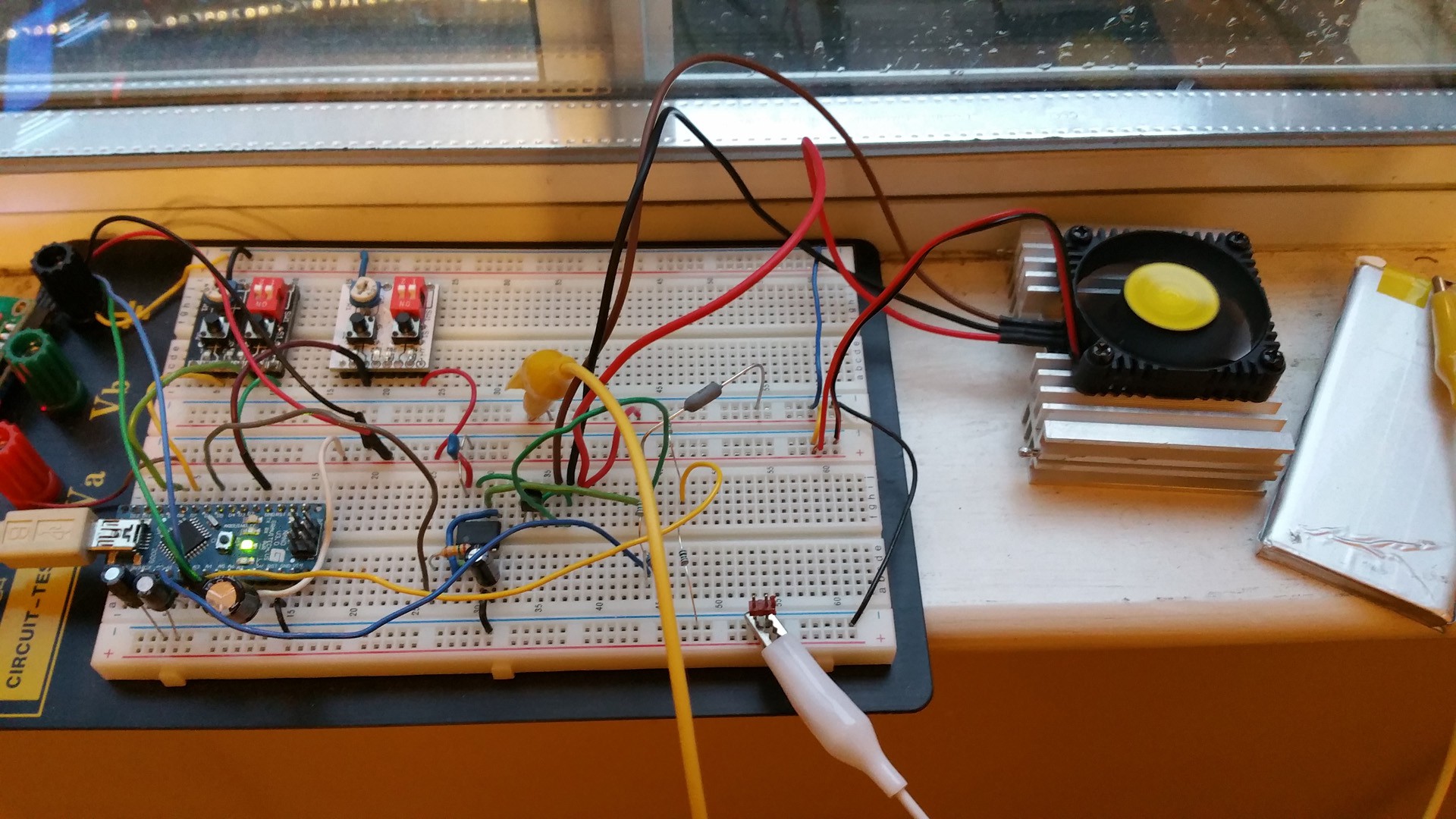
![]()
Here's what the hardware looks like now. I put a beefy heatsink + fan on the power transistor. The tiny heatsink I was using before got quite hot testing a 12V battery at 150mA. On the right you can see one of the batteries I've been testing. I think this was salvaged from an old macbook, and was supposed to be rated for around 2000mAh. I tested it at 300mA which resulted in 1540mAh and also at 500mA which gave me 1082mAh. This leads me to believe that this cell is somewhat worn out and has a high internal resistance. It would be a good candidate for something that needs decent capacity but with low current draw.
Now that the software is almost done and the hardware is tested, it's time to take this off the breadboard and build it into a proper enclosure. I was going to use a metal project box, but since I have a pretty good heatsink now I can get away with using a plastic box. The software works well enough but I'm not quite ready to release it. I've been lazy with commenting so I need to go back and add some information and tidy up the code a bit.
-
Progress!
12/22/2014 at 03:22 • 0 commentsAfter months of inactivity I've started working on this project again with some prodding from a friend. We prototyped the constant current load circuit. At first we tested the circuit just with a potentiometer providing the input. It worked fine, so we added an arduino to provide the PWM signal driving that controls the current draw. We also used a few analog inputs on the arduino to monitor the voltage on the current shunt resistor, and the input to the opamps.
We noticed that the voltages we were reading on the arduino were not stable at all, so we changed a couple things to improve that. First, by looking at our opamp input with an oscilloscope we noticed that the RC filter output had about 70mV of ripple. Not a whole lot, but something easily fixed by increasing the 15k resistor to 150k. That improved the readings a bit but didn't entirely fix the problem, so then we changed the code to take 50 samples in a row and average them. Now the readings are fine.
Because we're not using a signal conditioning amplifier, we don't have a whole lot of resolution to read the shunt resistor voltage. The current can be read to a resolution of about 10mA, which should be fine for this. I also decided to change the design of this project somewhat. I'm not so concerned about the charging, so I'm going to use a dedicated charger IC just to top off the battery before we do a load test, and recharge it after we're done. I also want this device to be usable without a PC, so I'll be adding an LCD screen and some controls to allow you to operate it completely PC-free.
-
Constant Current Load
07/15/2014 at 03:38 • 0 commentsI've designed the constant current load portion of this project, which you can see here:
https://www.circuitlab.com/circuit/vpe773/constant-current-load/
If you want to know how it works I describe the circuit in detail on that page, but the gist of it is that a PWM signal determines how much current the load will draw.
This circuit is fairly common, but typically uses an N-channel MOSFET instead of the two transistors I've used. A MOSFET would be problematic for my circuit, because the op-amp would have to output a voltage at least as high as the voltage across R2 plus the threshold voltage of the MOSFET, which is typically around 4V. With a 5V supply, that doesn't give me much room to work with. With two transistors set up as a darlington pair, I only need 1.4V for both transistors instead of 4V, which gives me a lot more breathing room.
Smart Battery Tester
An intelligent test device that tests batteries by discharging them to measure capacity