 Kuba Sunderland-Ober
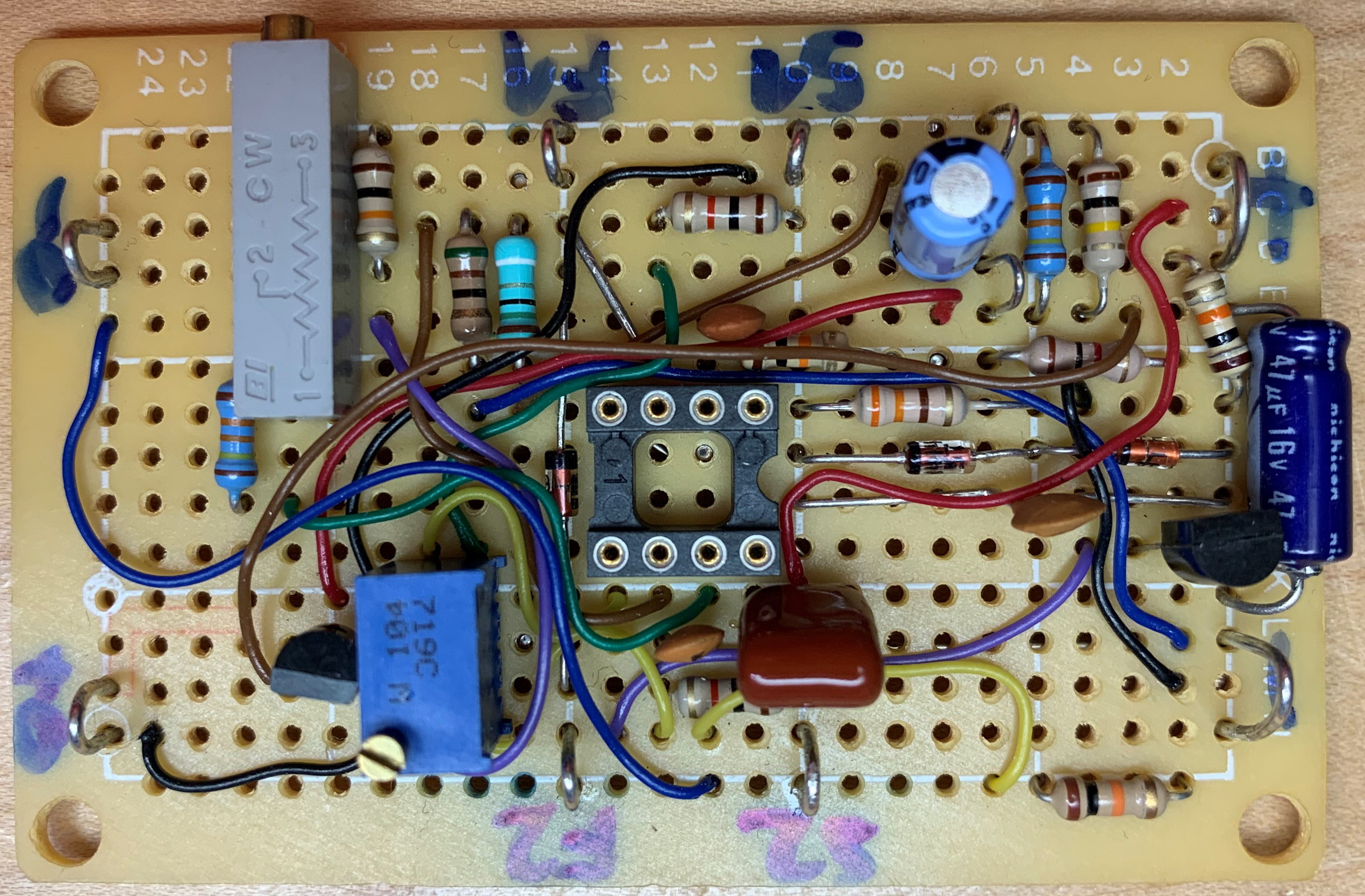
Just to see how close to reality the idea was, I put together the current source and the sense amplifier using a dual LM2904 on a protoboard. It behaved reasonably close to what was required, and I proceeded with a PCB layout for v1 rev 1.
A project log for SDO Milliohm Meter v1
A minimal 4-wire milliohm meter with 4.5 digit display
Just to see how close to reality the idea was, I put together the current source and the sense amplifier using a dual LM2904 on a protoboard. It behaved reasonably close to what was required, and I proceeded with a PCB layout for v1 rev 1.
Discussions
Become a Hackaday.io Member
Create an account to leave a comment. Already have an account? Log In.