The second prototype was soldered on a hot plate - maybe it is the reason why the accuracy is worse than for prototype #1, that was hand soldered?
Another source of error in this case is the output resistor R29 - its value is 1k in this case and that, together with input resistance of the voltmeter form a voltage divider that observably decreases the measured voltage. The difference of output voltage is +1mV for 8.66V set voltage when measured before R29!
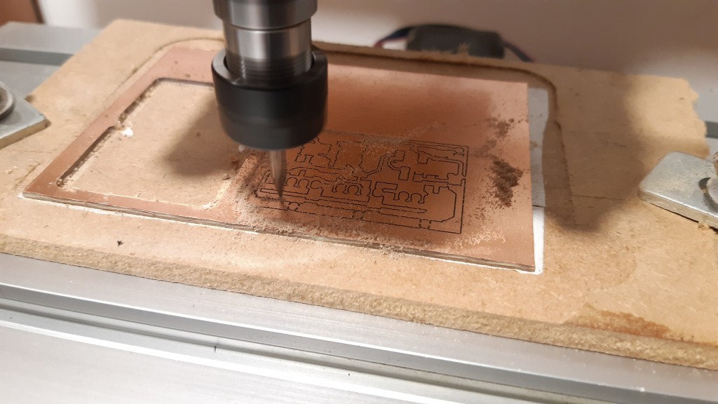
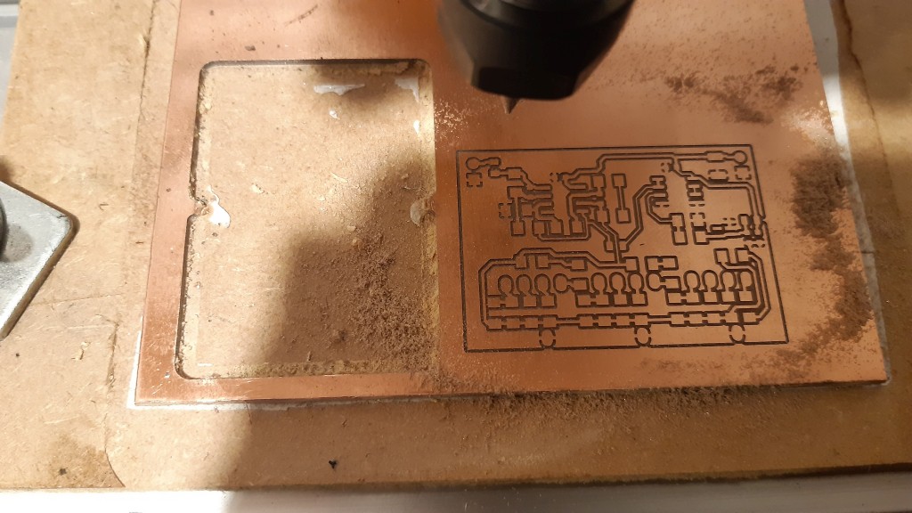
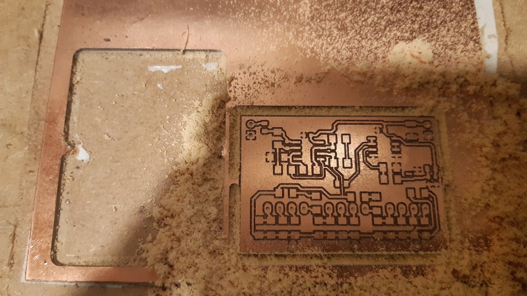
This is the short pictorial story of prototype #2 being created:
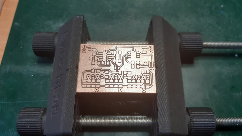
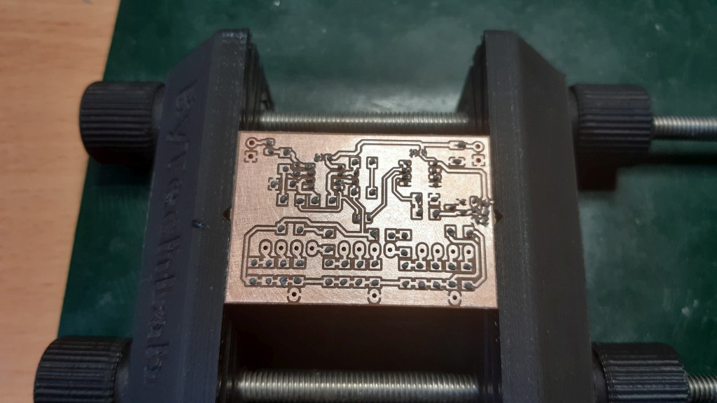
Milling, drilling, outside cutting:
The long past-due SnPb solder paste is dispensed using a handheld dispenser:
The components are placed by hand:
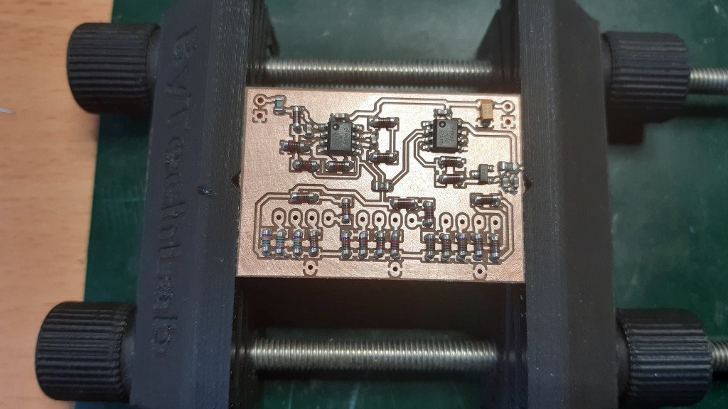
A homemade hotplate is used to solder everything together (note the fume extractor above-left):
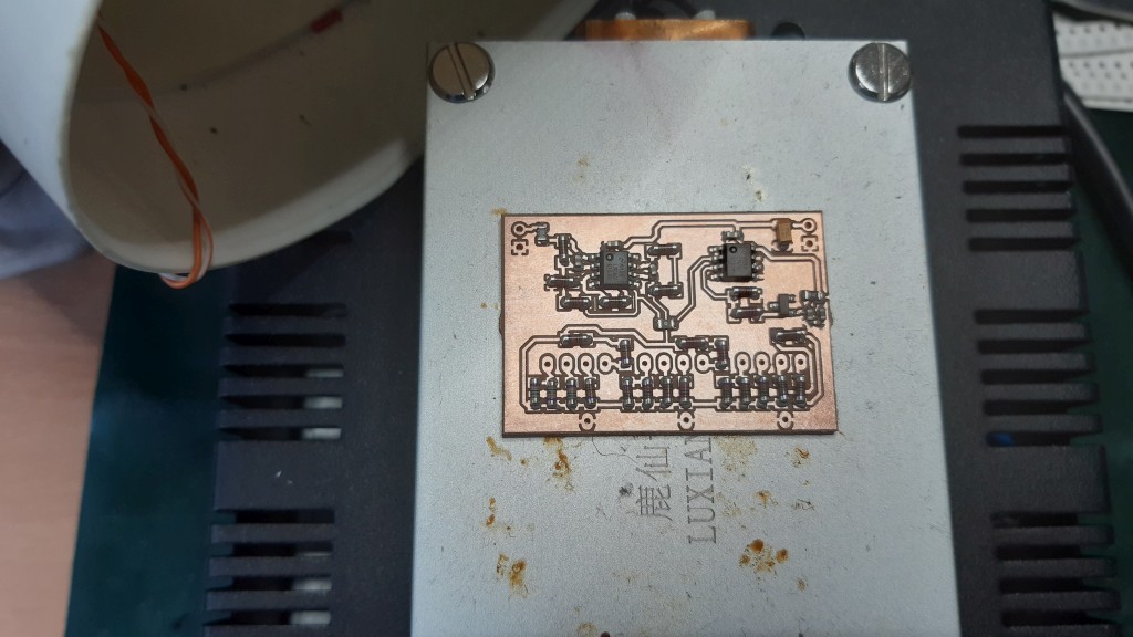
SMD components are soldered, but the copper got discolored due to the heat and lack of protection layer on top:
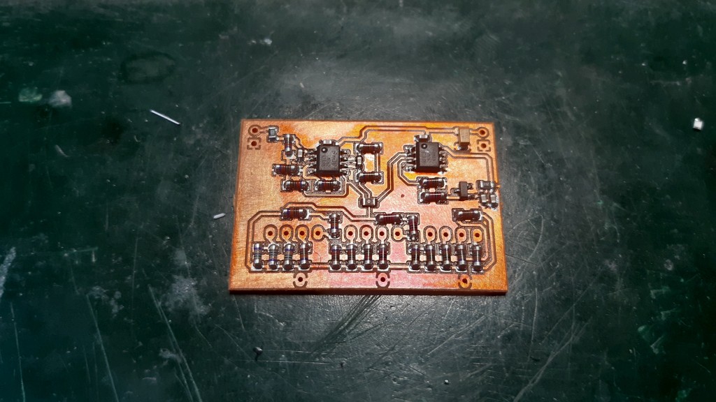
The remaining part was to solder the through-hole switches and the power supply input wires and the output wires.
Discussions
Become a Hackaday.io Member
Create an account to leave a comment. Already have an account? Log In.