-
The Legs
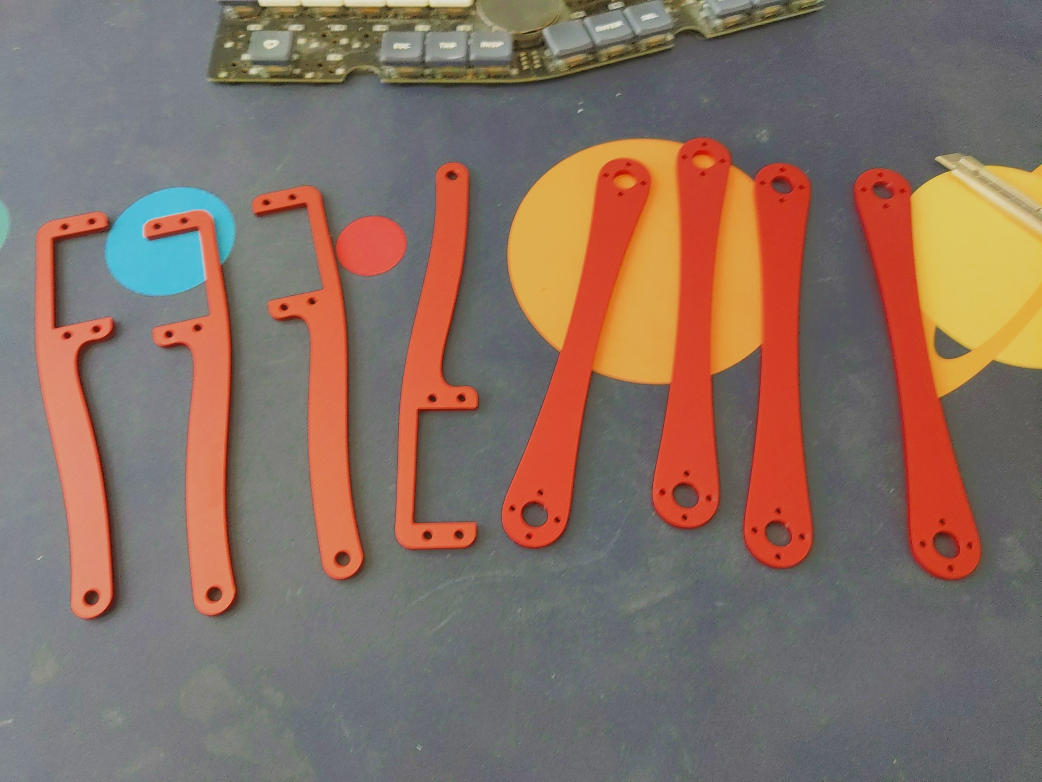
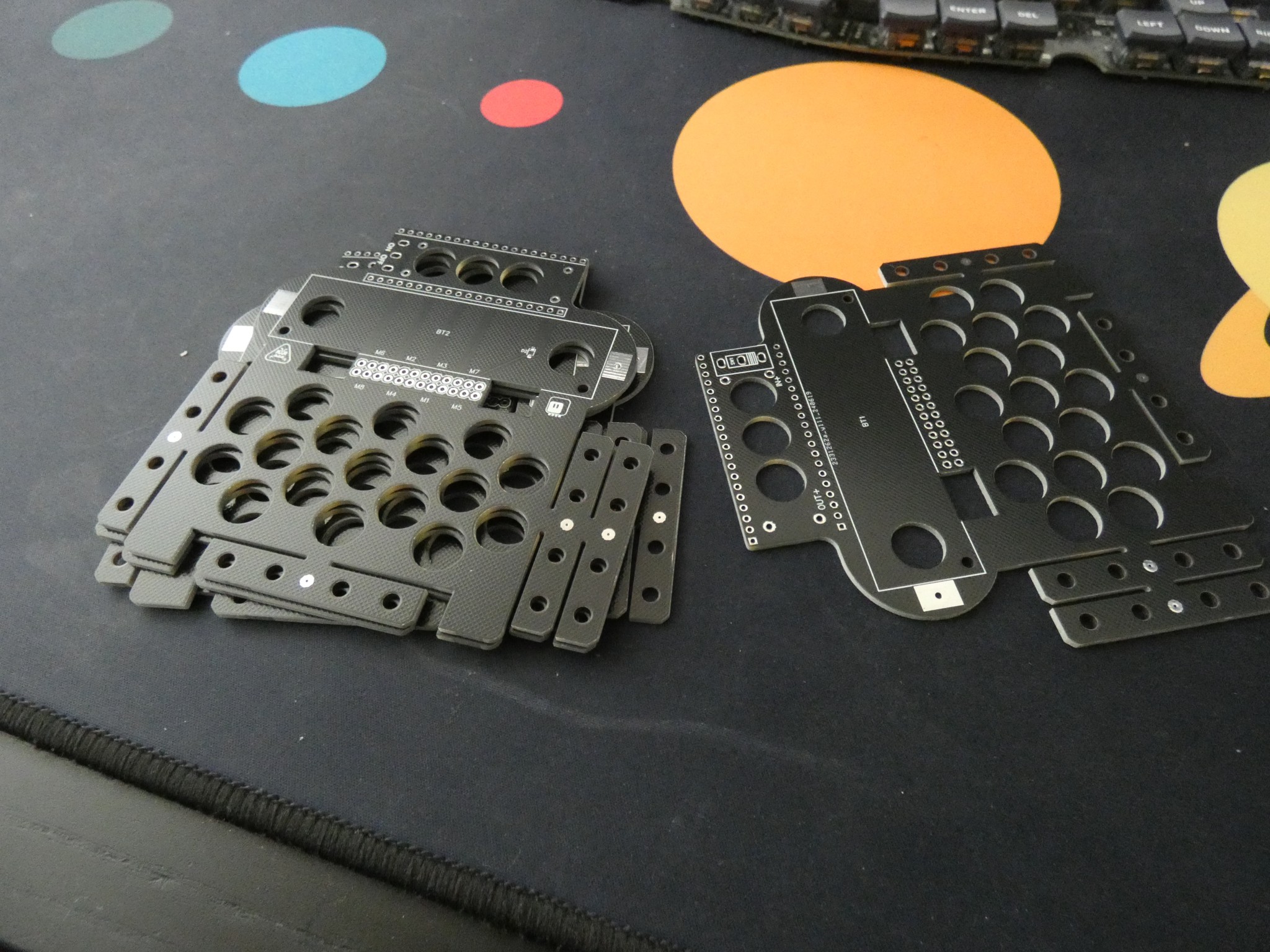
07/03/2024 at 18:02 • 0 commentsIt took a while (because I picked the cheap and slow option), but the leg parts finally arrived.
![]()
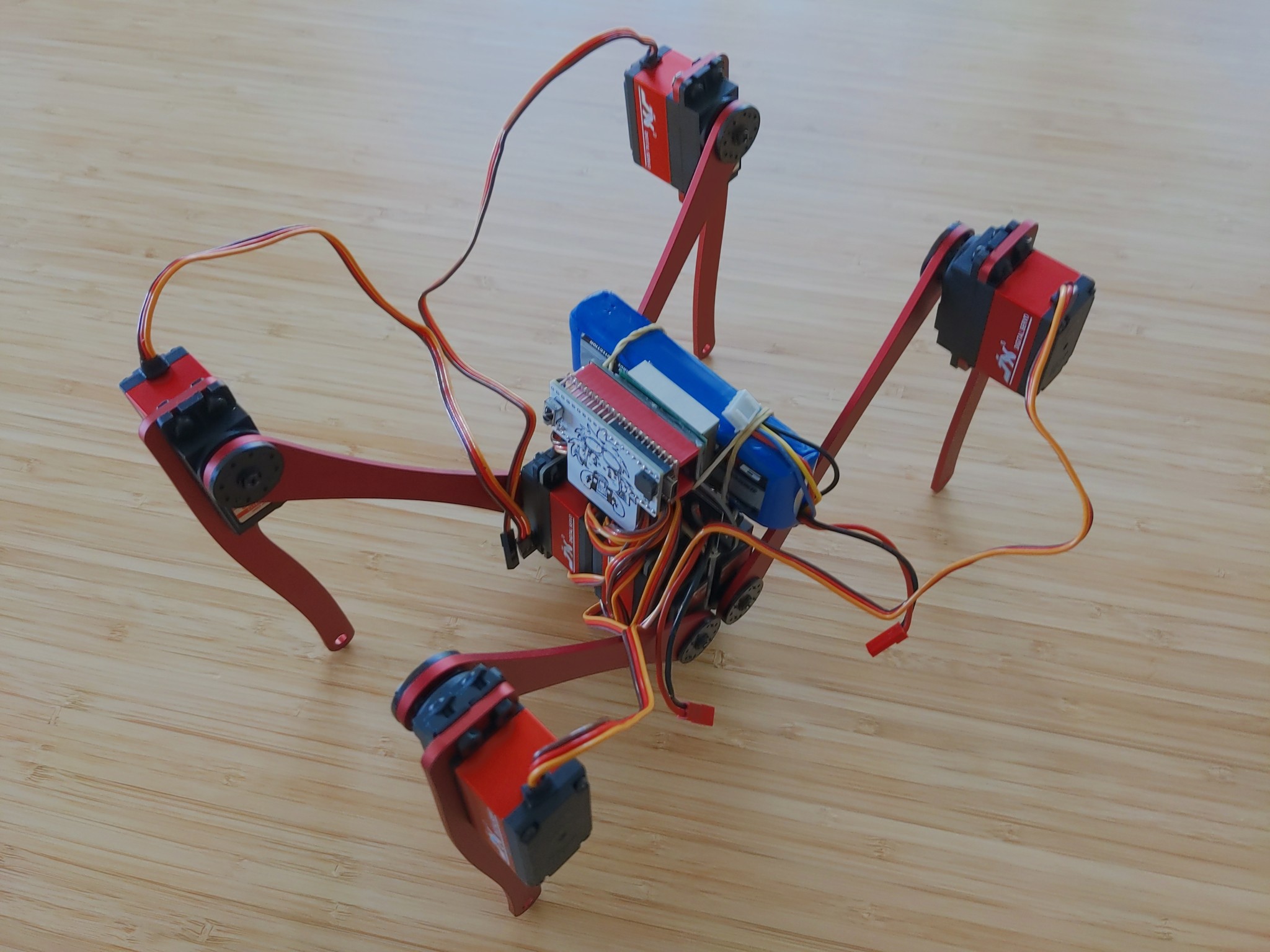
They look great: 3mm thick anodized aluminium. Very solid and pretty light too. So I assembled the robot with the PCB body first, just to see how it all looks like:
![]()
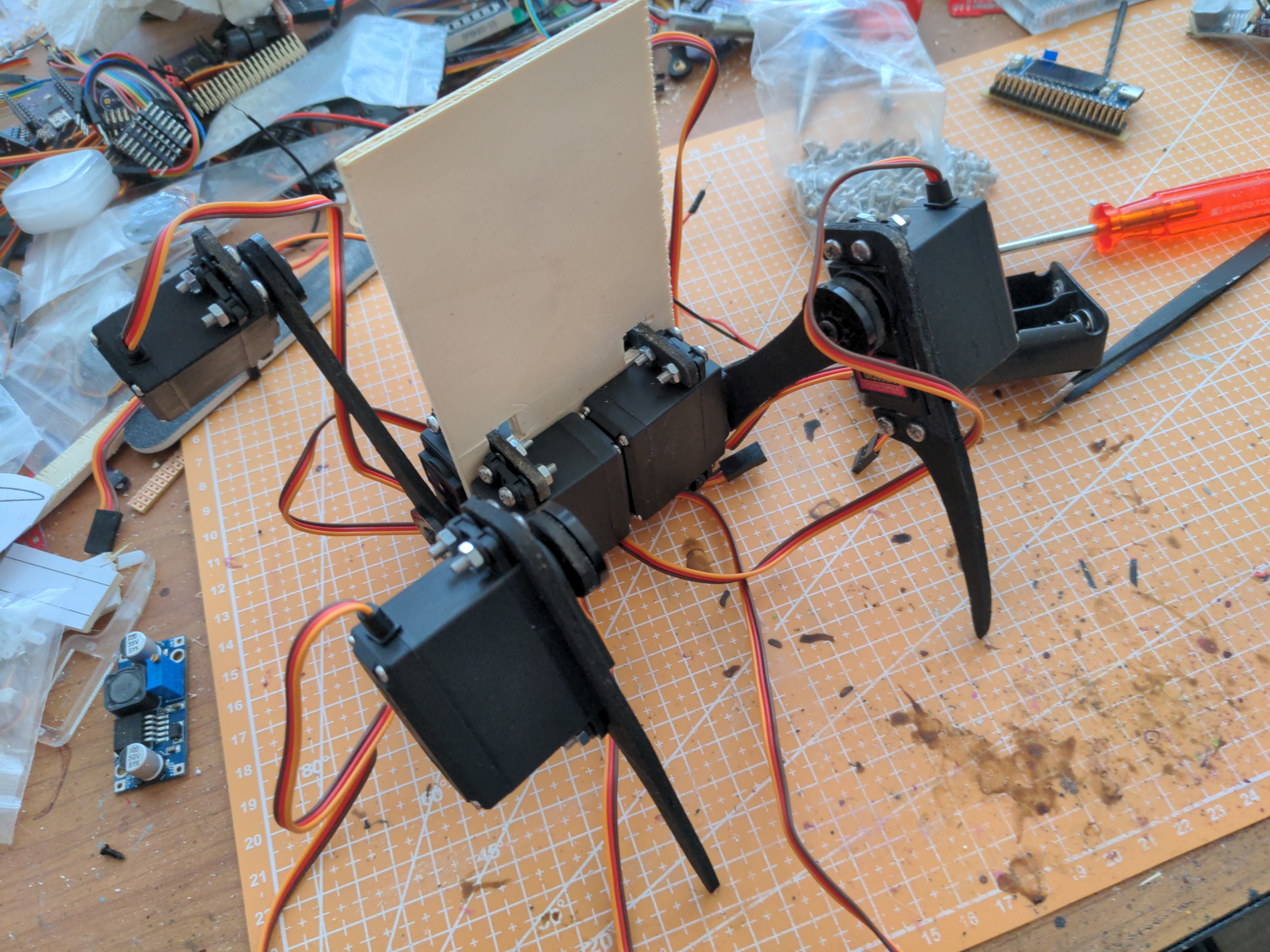
Turns out that those servos are really beefy. In fact, they are so strong and fast, that my lazy code, which tells them too move from one end to the other when making a step, makes them draw so much current that the 8/15A regulator shuts down. This is more of a software problem, though, than hardware — the power is perfectly adequate when the servos are moving more gradually and don't make sudden movements all at once. There is also a problem that I already noticed in the first version of Big Bug, that is even more pronounced now with the longer legs — the robot is tilted to one side for some reason. I initially thought that it's because the servos have asymmetric response to the PWM signal, moving faster in one direction than in the other, but then the difference would be between diagonal legs, and it's clearly a left/right asymmetry. I will need to investigate that closer.
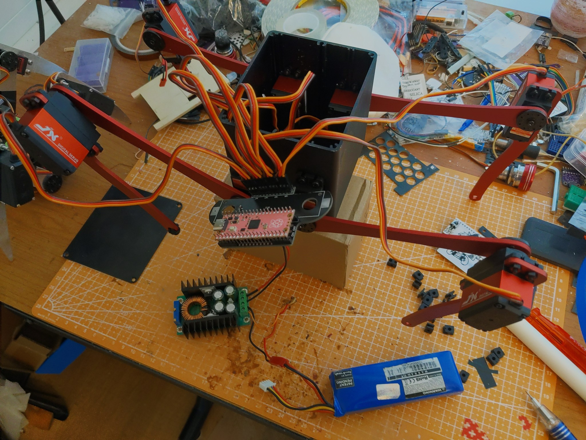
With the initial tests done, I proceeded to move the robot to its proper aluminium body.
![]()
I used one more spare PCB from the PCB body, but I cut off the mechanical part to which the servos were attached, so that it will fit inside the case better. I also experimented with several different buck converters, but in the end settled on the 8/16A one that I used initially. I ordered a few more to try later, too, so I might still change it.
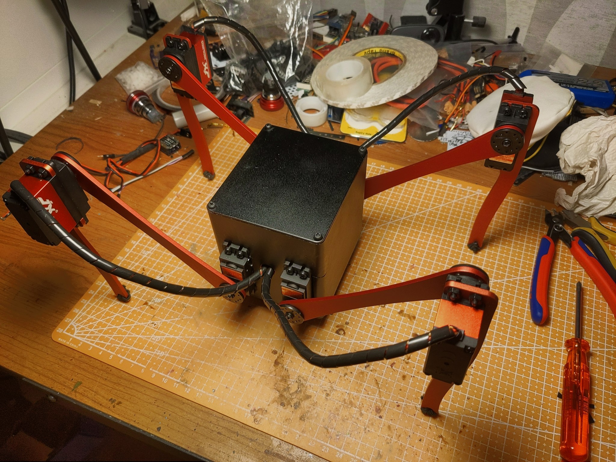
The total weight of the whole robot is just shy of 1kg, which is not too bad. I might actually make it even less by replacing the case lids with PCBs (I don't feel like drilling all the holes for the power switch and USB in the original lids), and using a smaller battery.
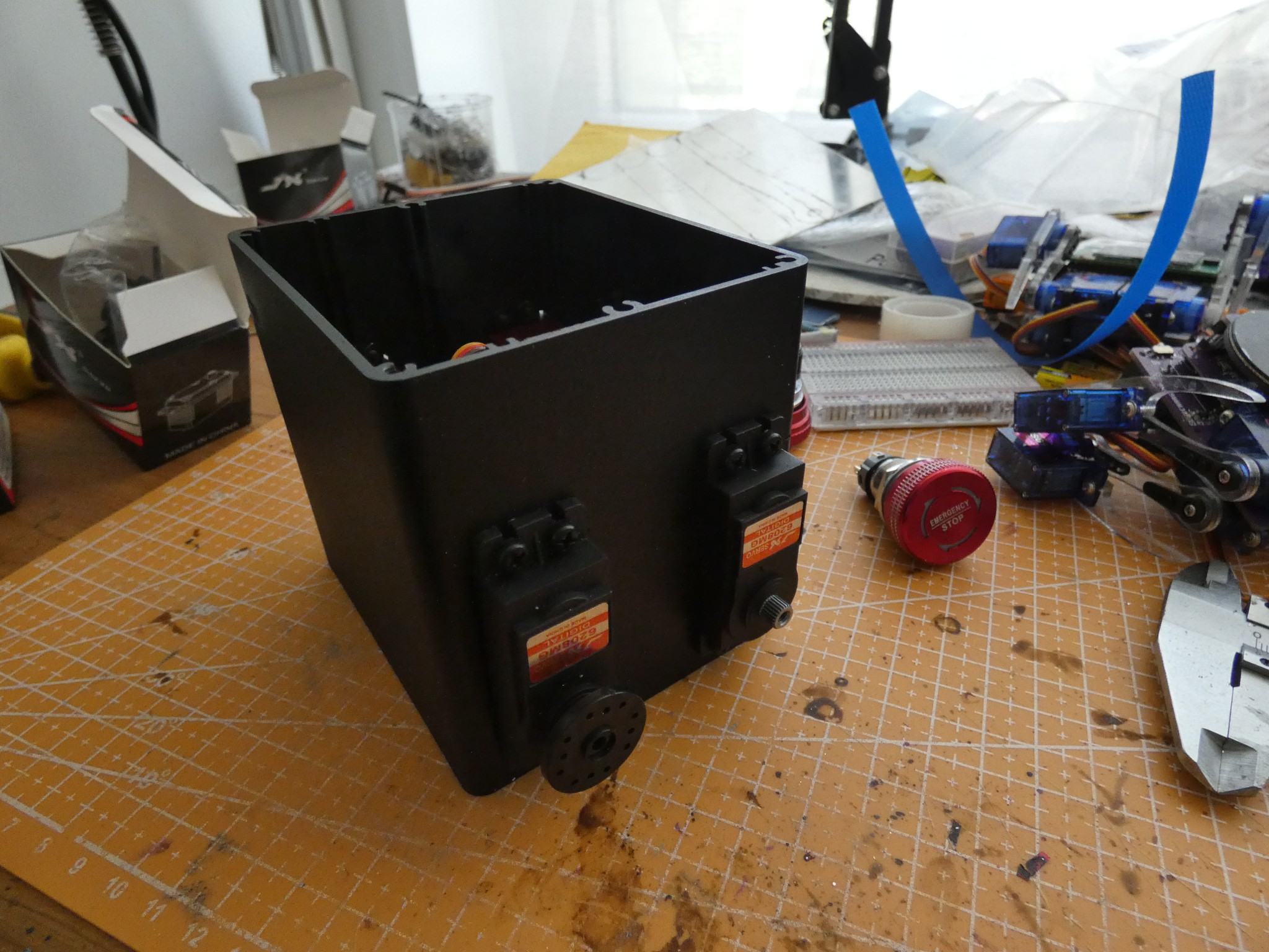
I drilled the holes on the sides for the servo cables, added some plastic cable management thingies, wrapped some rubber strings on the feet, and closed the lid:
![]()
Now all that is remaining is, as always, programming. And waiting for the additional parts.
-
The PCB Body
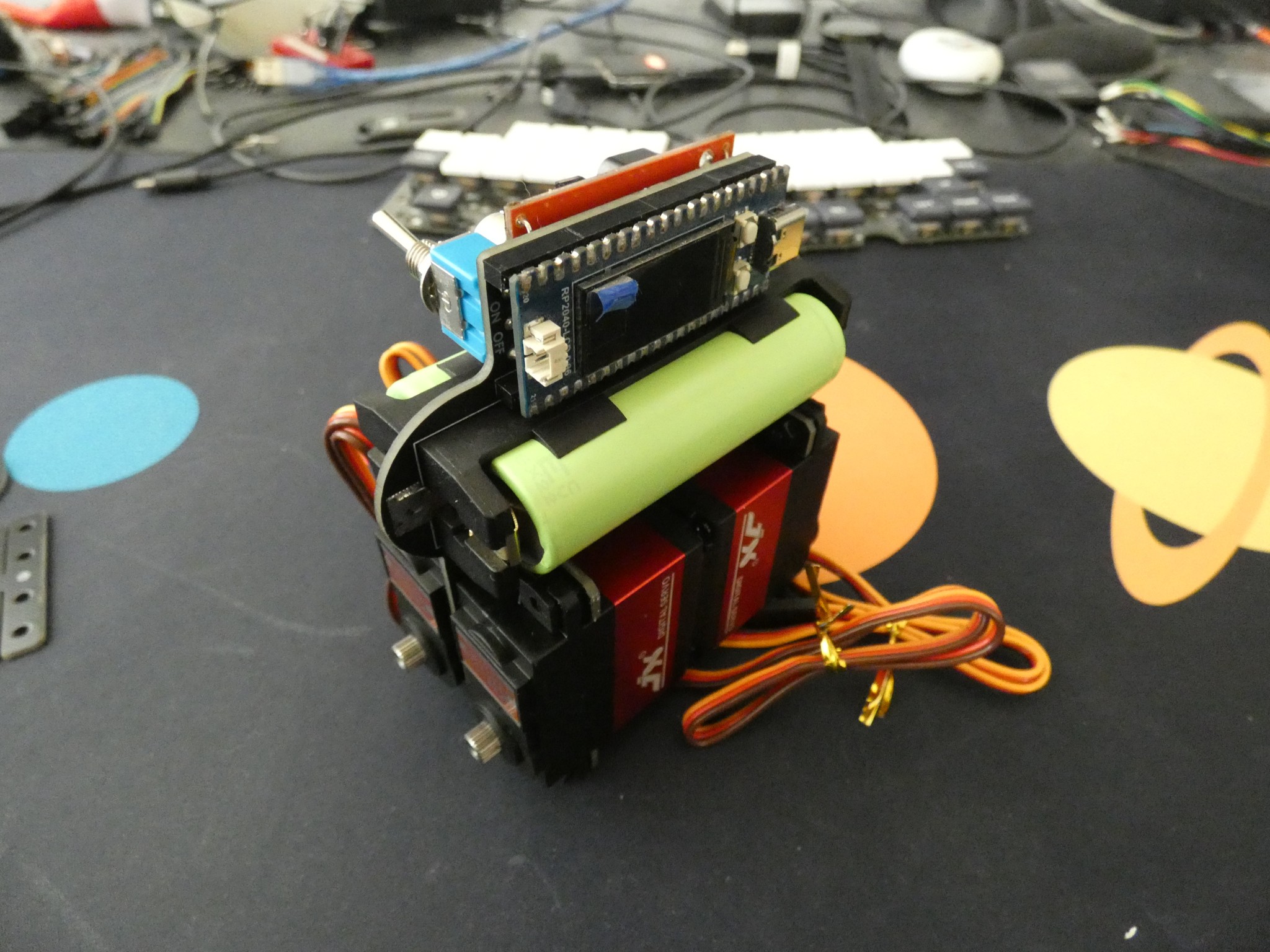
06/24/2024 at 19:41 • 0 commentsThe PCBs arrived (is it just me or are they really getting faster recently?) today.
And I assembled one, just to see how it all fits together.
Apart from the fact that the switch works in reverse (on is down), everything is pretty much as expected. I used nylon screws to save a bit on on weight (and because they are black and look better).
Now I'm only waiting for the legs. They should be fabricated next week, and we will see if they arrive before I travel.
-
Version Two
06/19/2024 at 22:30 • 0 commentsThe robot was built to see if it would work, and I have to say that it worked pretty well so far. However, after taking it to several different events, I now have some ideas about how to improve it for such events specifically.
The main problem I have is that the robot is really to slow to walk around with it. As such, it's mostly spending its time on the time, waiting to be switched on for a few steps to show to the passing people, and switched off before it falls off the table. Its size is also a bit awkward. It's too big to really do anything useful on the table, but too small to be safe from being trampled on the floor.
So now I want to build a second version, using faster servos and longer legs. That should solve both the problems. I also want to try and make the body look less like a bunch of duct-taped garbage, but that's a secondary consideration.
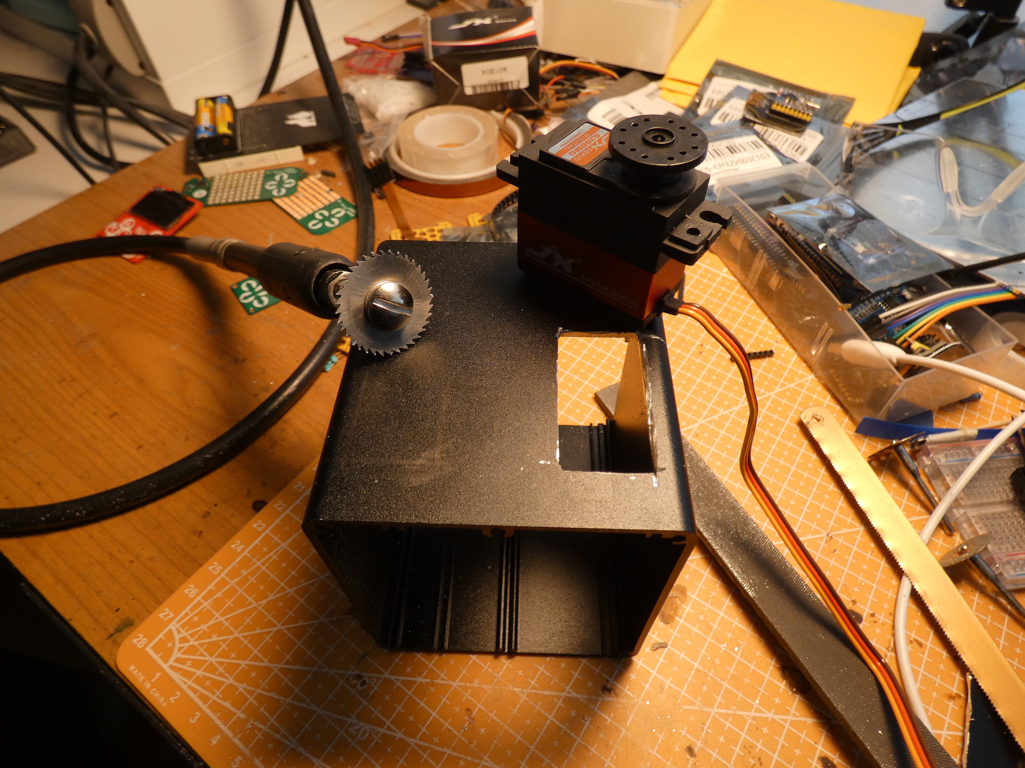
I already have the servos for the second version. I went with the JX PDI-6208MG, mostly because they are roughly the same size as the MG995 I used in the first version, but should be about twice as fast. I also got some aluminium cases to see if I can use them as the body. One such case seems to be particularly suitable, so I went ahead and cut some holes in it to mount the servos:
Cutting thick aluminium with a dremel turned out to be harder than I anticipated, but with some struggle, I got all four holes for the servo, and the accompanying mounting holes done, and then painted the enclosure with black spray paint to make all the scratches less obvious.
As for the legs, I was planning to cut them from 3mm sheet aluminium again, but then I realized that some of the usual PCB fabs also let you order CNC cut parts. Initially I tried three of them, but with the pricing they showed, I started preparing the hacksaw.
But then I thought about the fact that they also do bead-blasting and anodizing of the parts. I imagined nice red anodized aluminium legs, and I went to try some more fabs. One of the offered to make the parts for 1/3 of the price of the others, and that is acceptable for me for a one-off project, so I ended up ordering the parts anyways.
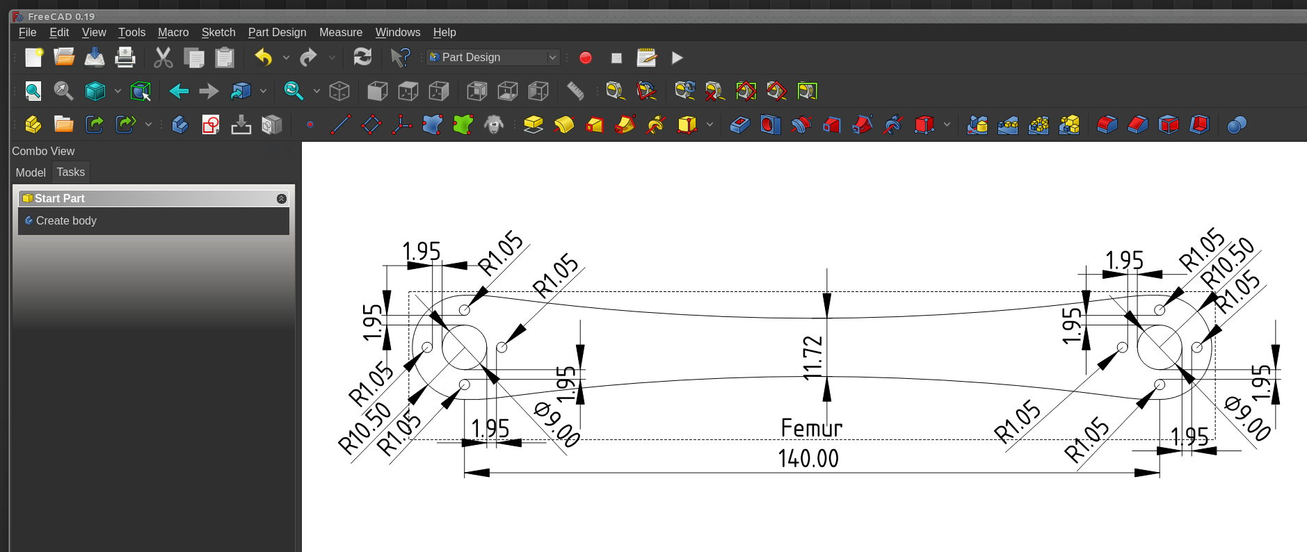
They wanted step files, so I took this opportunity to learn to use FreeCAD a little bit...
![]()
I know, I know, this is horrible. But it's the step file that counts in the end. With the leg parts ordered and scheduled to arrive in some two weeks, I got to work on the electronics.
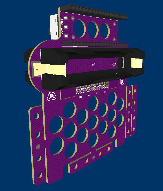
I don't need anything too fancy here. I wanted to use the pi pico, to have enough extra pins for things like speakers, blinking LEDs, extra moving parts and so on. I considered using a 3S lipo battery pack, but it's considerably heavier than the 2 18650 batteries I used previously, so I kept those. I looked at the buck converter chips available, but I didn't find anything that would be much better than just using a ready buck module, so I just left holes to connect that. The rest is simple: power switch, servo sockets, and a shottky diode for the pi pico VSYS (I might replace it with a different diode with a larger voltage drop, to raise the voltage for the servos).
![]()
Just in case, I made the PCB shaped just like the body of the robot in #Wee Bug and #Fluffbug, so that if the aluminium case proves to be too heavy or otherwise problematic, I can revert to the taped garbage looks. I moved the batteries to both sides of the PCB to make the weight more evenly distributed, and I added a bunch of break-off parts for attaching the servos.
Now with the PCB and the leg parts on order, all we have to do is wait.
-
Edward Knifelegs
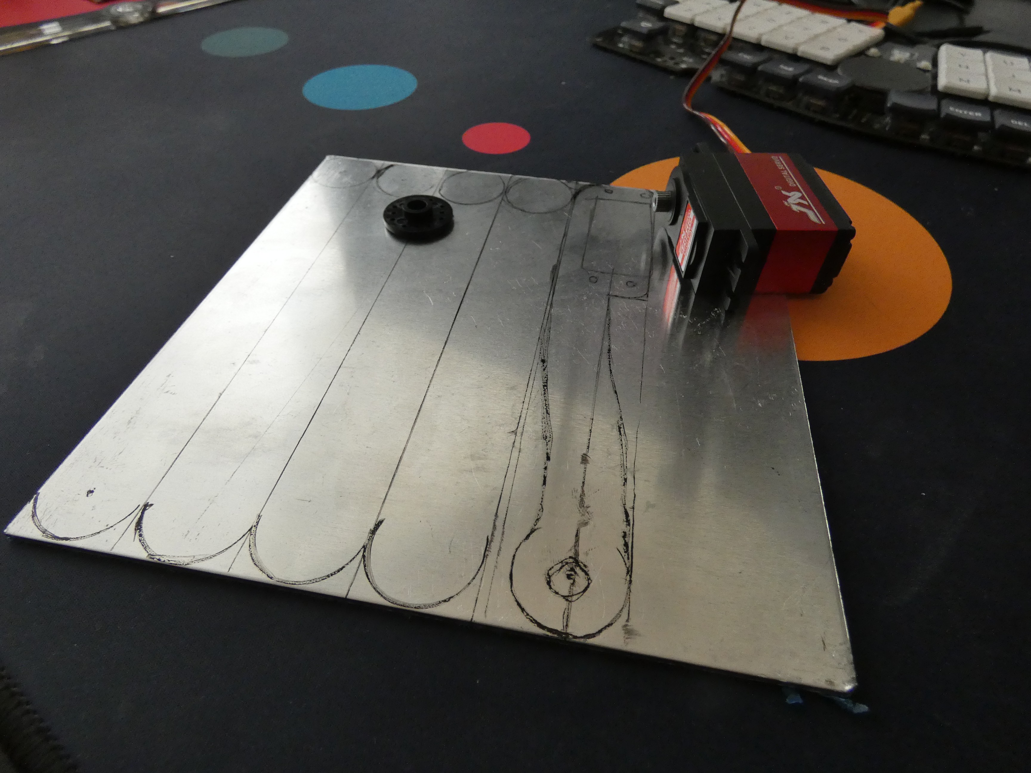
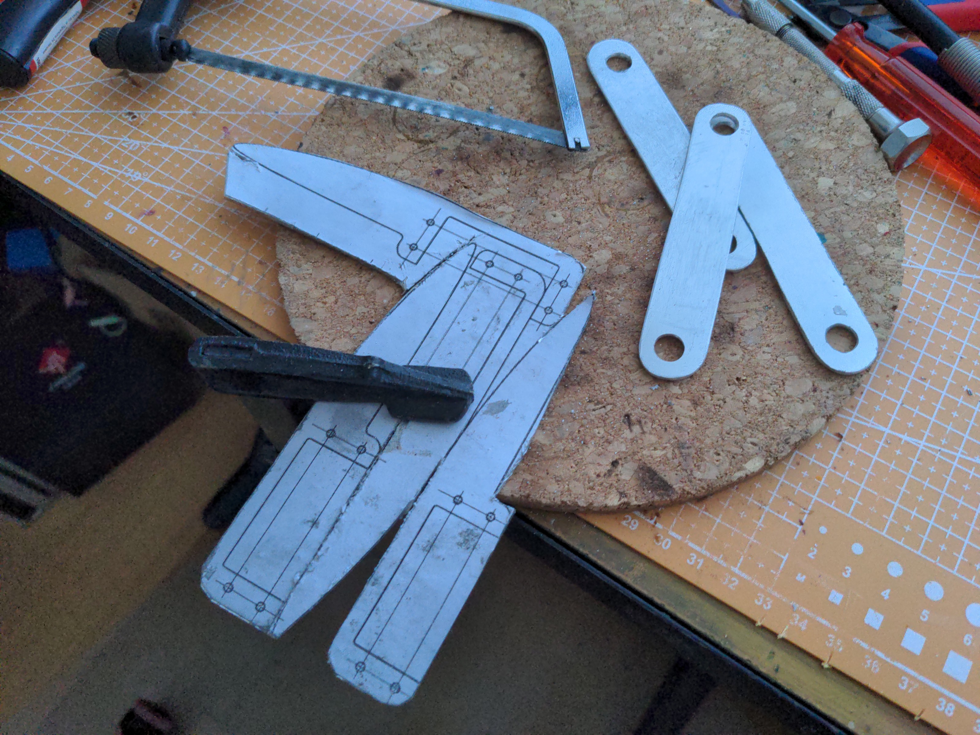
07/04/2023 at 22:29 • 0 commentsThe 2.5mm aluminium sheet arrived, and I spent a weekend sawing it with a hacksaw and drilling by hand and with an electric drill.
![]()
If you plan on doing anything similar yourself, I have two tips for you. Get the sheet attached to something heavy securely, a good vise or clamps can speed up your sawing greatly, and don't arrange the parts the way I did in there, interlocking, without a straight sawing line separating them. It's much easier if you can separate the elements with straight cuts first.
![]()
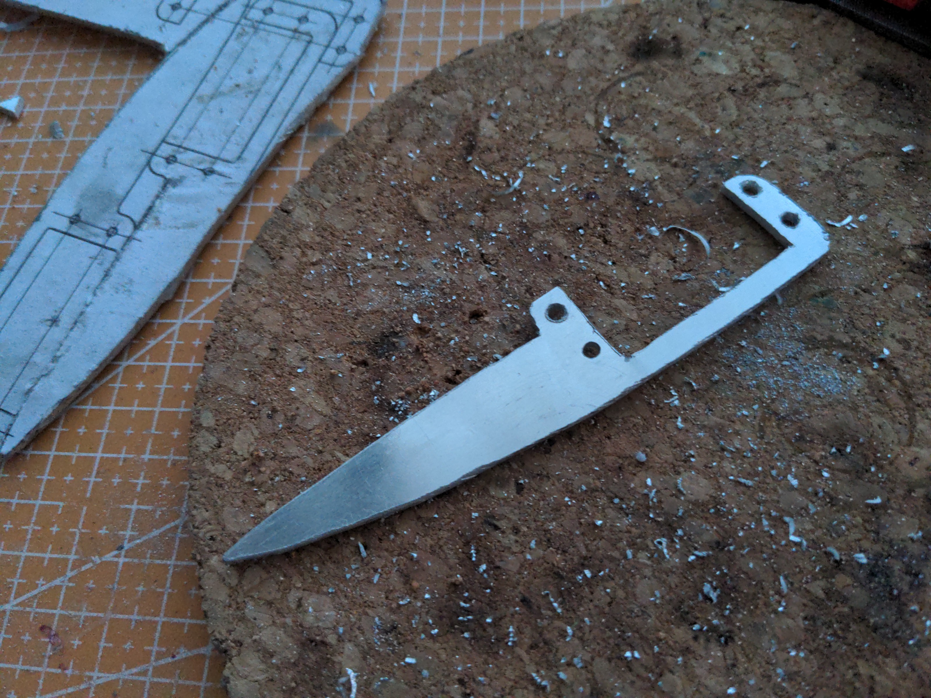
Then some drilling and a lot of filing, and we have workable legs. Note that it vaguely resembles a knife, mostly because it's made of shiny metal. But all the edges are rounded, and the tip is not sharp either.
![]()
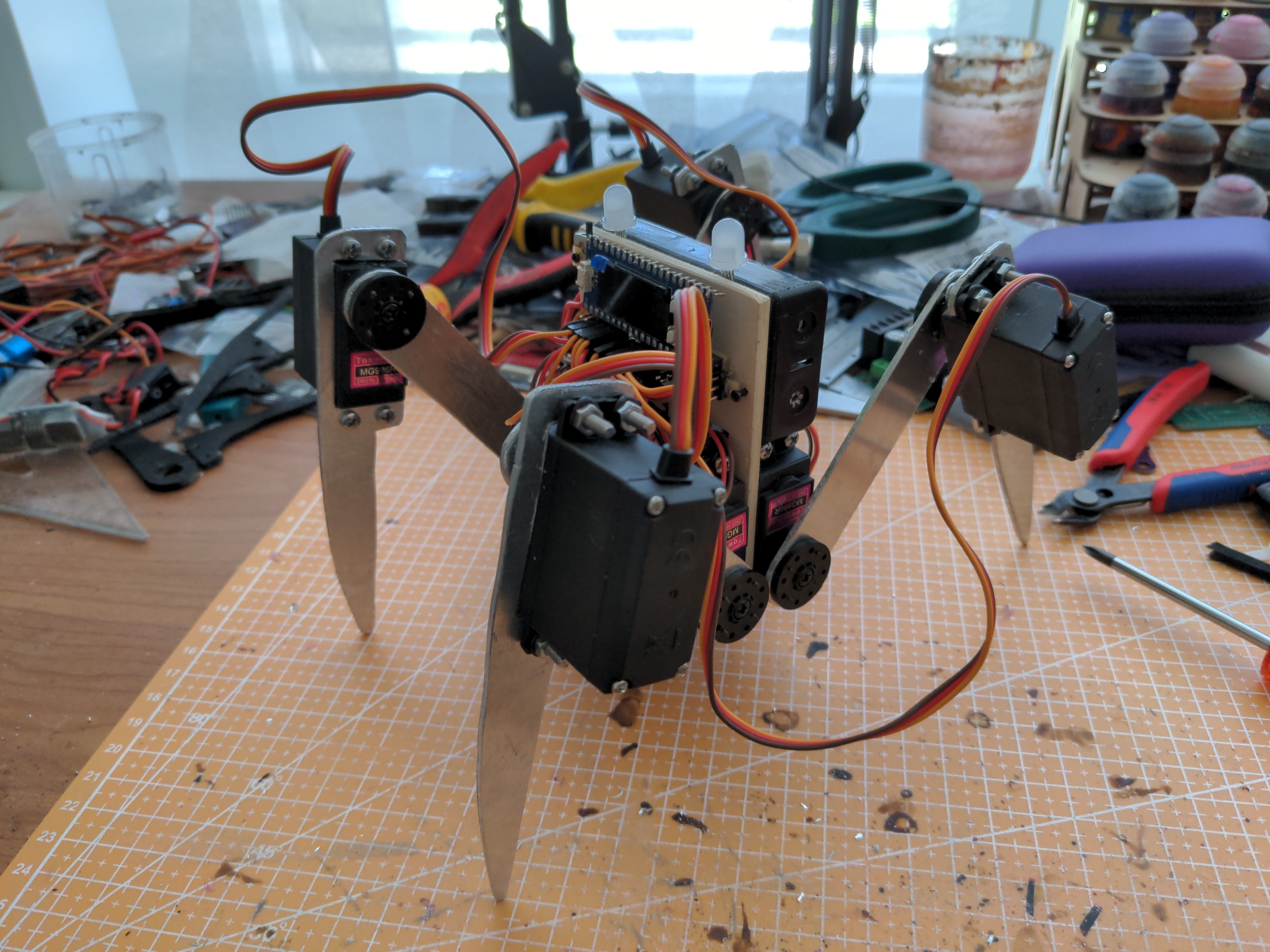
Finished robot. Yes, it does look like hacked by hand, and it would look much more "finished" if I used a cnc machine or some kind of other cutting service. But I happen to be happy with that looks, and I don't plan on making more than this one prototype. I added some RGB LEDs to act as eyes, but they are not connected to anything right now. If I ever replace the wooden body with a custom PCB, I will probably include footprints for those LEDs and connect them to spare pins, but for now I haven't decided if I will ever go for that.
![]()
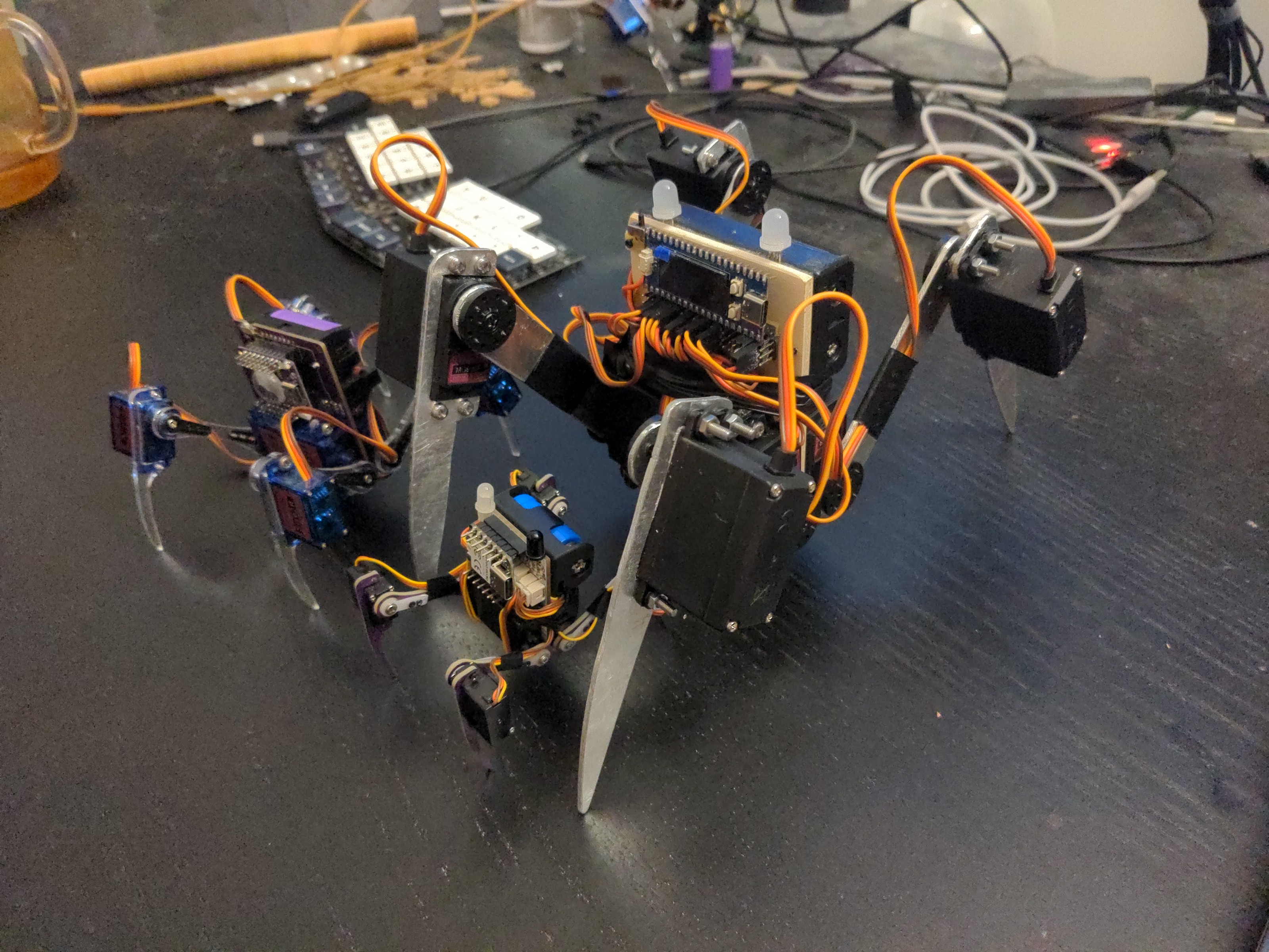
Finally, a family photo of all three bug robots: #Wee Bug, #Fluffbug and Bigbug all together.
-
Material Alternatives
06/02/2023 at 00:57 • 0 commentsAfter building and testing the robot, I have some changes to consider.
![]()
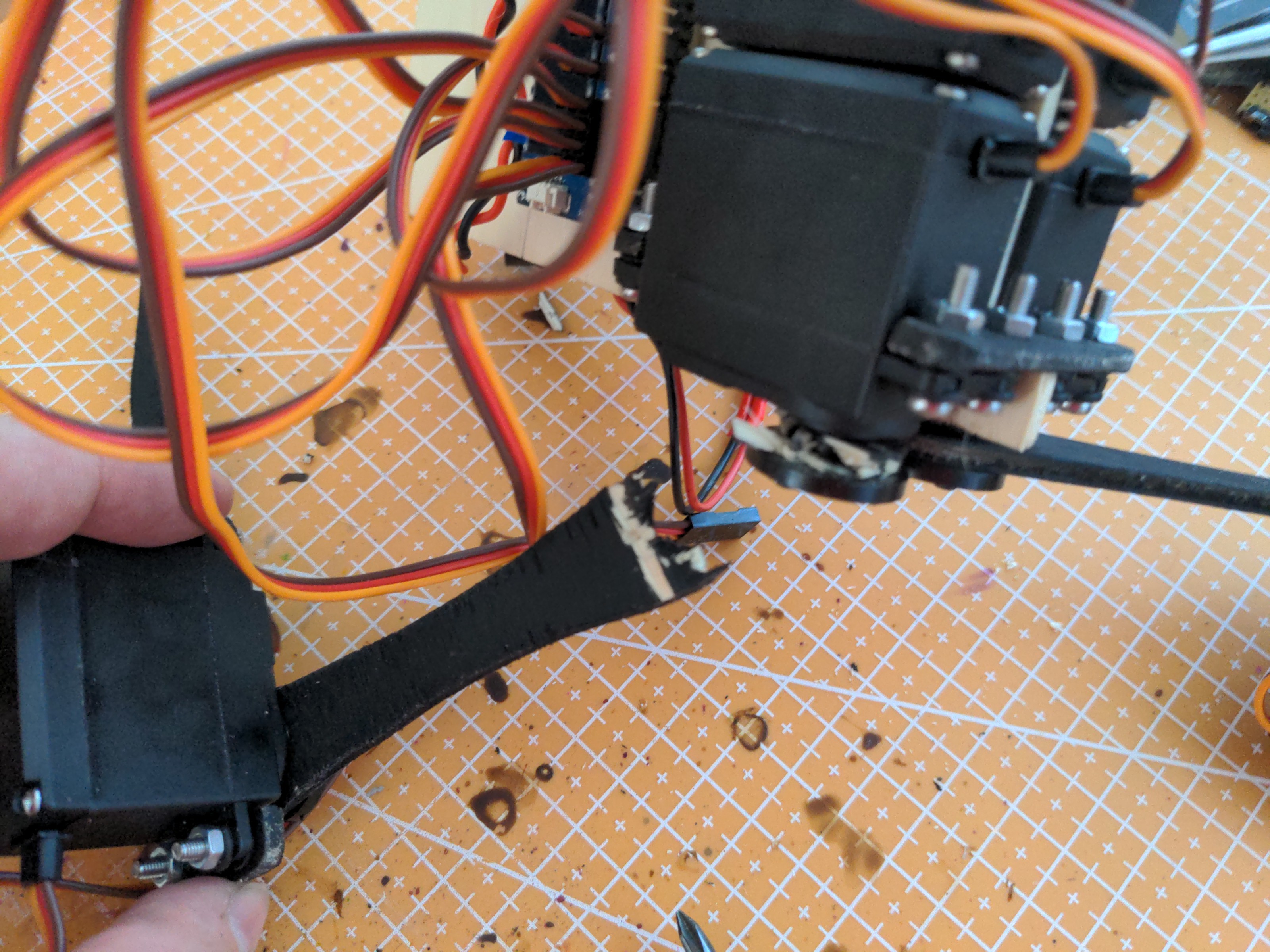
First of all, the plywood I used is not great for the legs. Surprisingly, it's not the weight of the robot resting on them that is the issue, but the fact that the parts twist, especially when the robot tilts from side to side to unload its leg before raising it, and the whole thing becomes rather wobbly.
Now, what are the alternatives?
I could go with stronger plywood (the one I used was sold together with my scrollsaw, and is rather soft), and perhaps laser-cut it this time. Or I could go with laser-cut acrylic like in Fluffbug, it should still be stronger than this.
Or I could really go all the way, and use 2.5mm aluminium sheet. It's soft enough to cut by hand with a hacksaw, and should give me plenty of strength. I'm tempted to do it, especially if I can cut it at the hackerspace and avoid the mess at home.
In either case, I think I will also need to make the legs a little shorter. I was optimistic and really scaled them 200%, but that makes the robot look really tall and narrow, and doesn't help with stability. Shorter legs should make it easier to fine tune the gait, no matter what they are made of, and this is not a race, so I don't really worry about the speed.
-
Initial Decisions
06/02/2023 at 00:47 • 0 commentsBuilding a smaller robot is easy, as everything is cheaper, relatively stronger, and the only worry is fitting everything together in the smaller package. Building a bigger robot is a challenge. Everything is more expensive and costs more to ship, takes more power and has smaller margins for strength. And inertia rears up its ugly head. So we need to plan carefully.
Most decisions will be driven by the choice of the servos. The MG996R are almost twice as big as the SG92R I used for Fluffbug, so we will scale the whole thing proportionally. The 23mm width of the SG92R becomes 40mm width of the MG996R, and everything else grows with it.
I'm not going to use a PCB for the body, it would cost too much, and I'm not sure at this point how big it would need to be to fit all the components, so instead it will be a piece of plywood, cut by hand to fit the servo size. I'm going to use the same hand-cut plywood for the leg parts, at least initially, because getting them laser-cut in China and shipped here would be a bit expensive, and I don't have enough social skill to ask for lasercutter access at my hackerspace.
![]()
For the brains, I think I will go with another Pi Pico clone, because it's easy to add servo connectors to it using just prototyping board – I'm not making a dedicated PCB, at least not just yet.
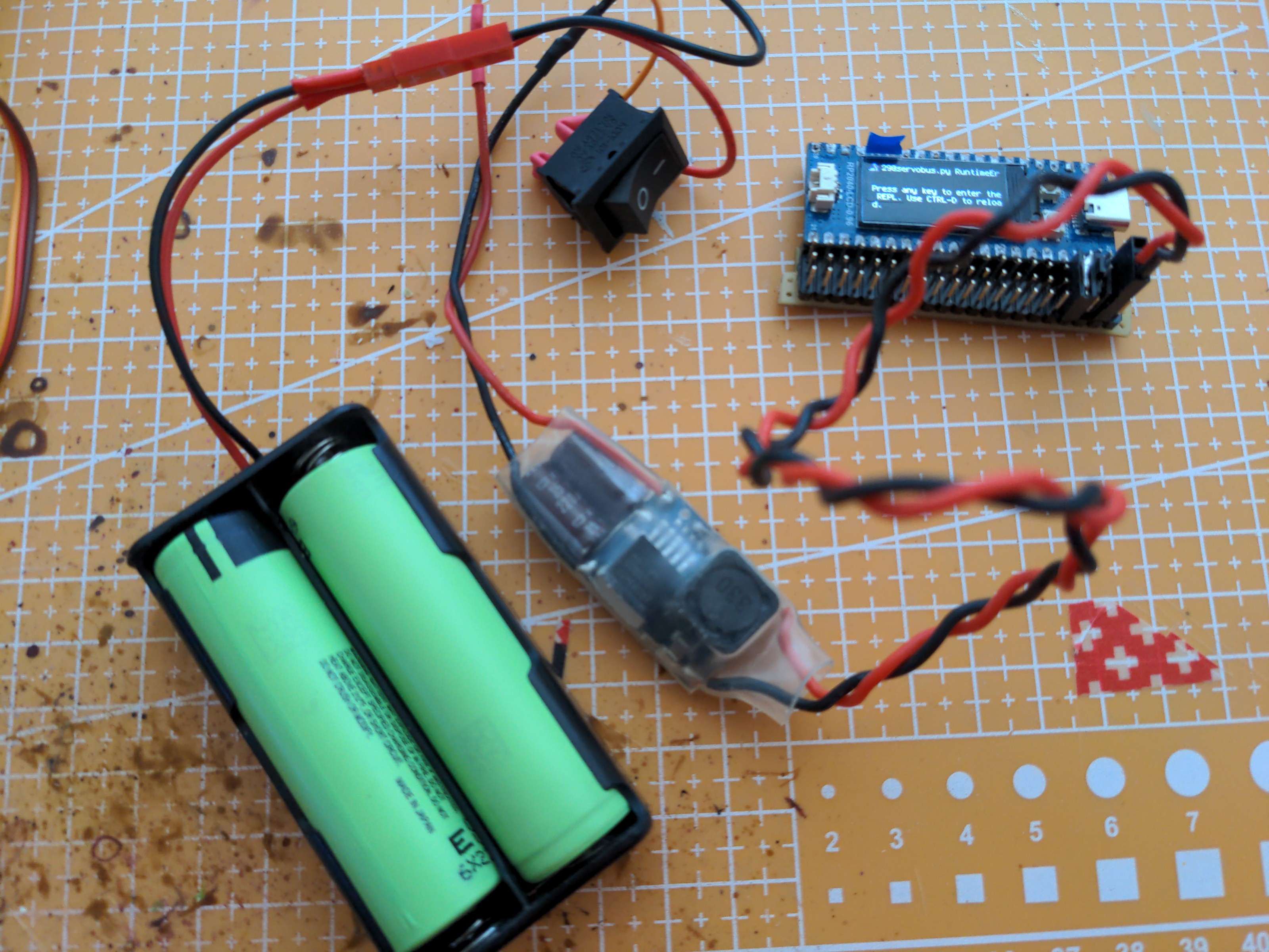
The power needs a substantial upgrade. I think I can no longer use a single 1S lipo cell. I will go with two 18650 cells, with built-in protection. That means there isn't going to be a charging circuit or an on-board protection circuit, which simplifies things a bit. On the other hand, I will need to get that 8V to the cozy 5-6V for the servos and electronics, so I will need a buck converter in there, and one that can handle considerable currents. I have some no-name UBEC modules in my drawer, so I'm going to try these, and if that doesn't work, a 9A buck converter is on order.
![]()
That's pretty much all I should need to get the basic walking going. Once I got that, I will see about maybe putting a Linux single board computer on it, or other things.
 deʃhipu