 Ahron Wayne
When we last had left off, we had stripped down a lot of our machine and physically connected to the motors. Woohoo! We're on our way to collecting the infinity stones to a CT scanner (and hopefully of the laminography variety).
Over the last few weeks, I've worked on getting a few more of the stones to work --- specifically the detector and source. And I can happily say: They both work! Kind of! As the title says!
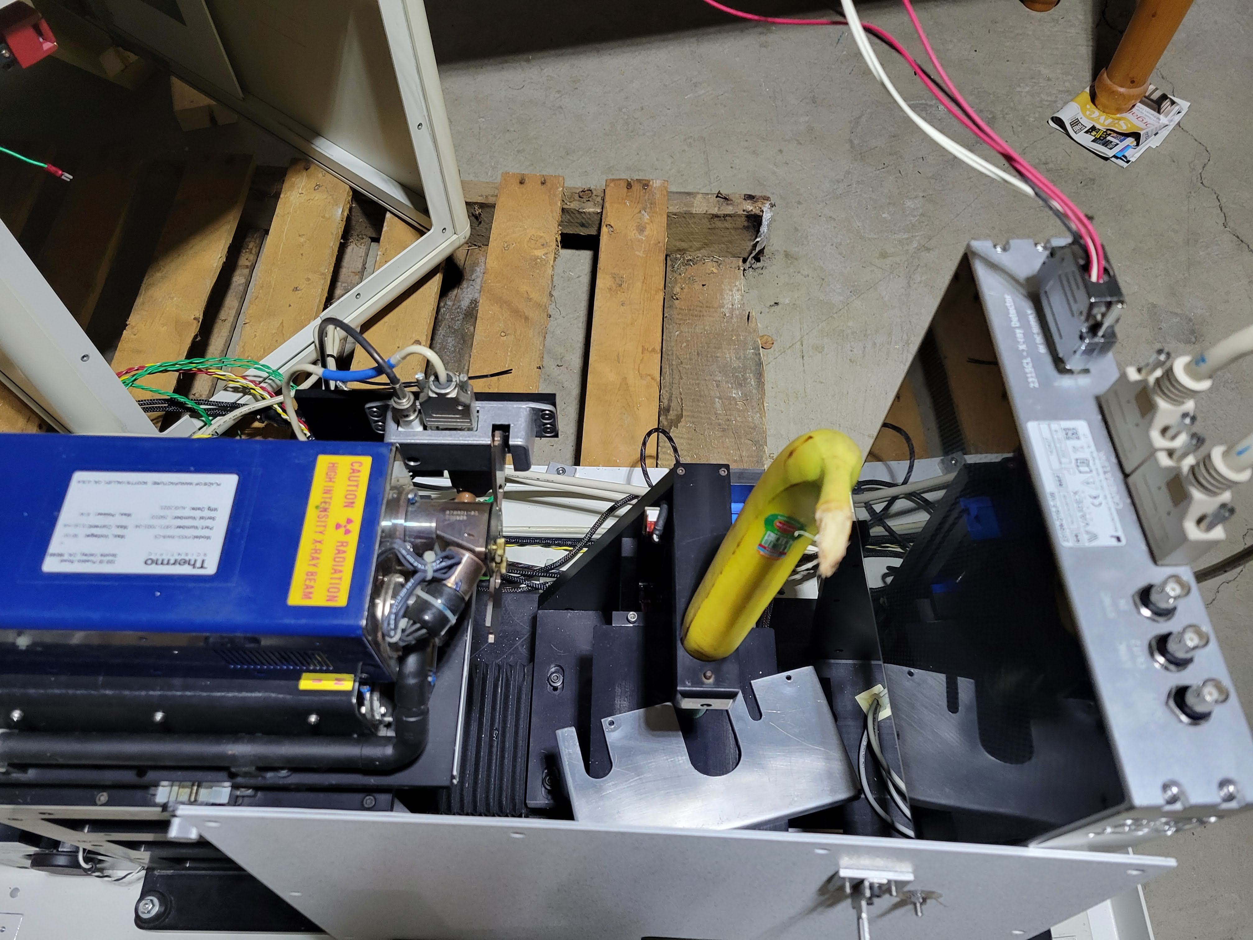
In this log I'll talk about the detector --- hopefully I will unbork the source in time for the next log. it's a Varex/dexela/perkin elmer/whatever ebay 2315 flat panel. Probably meant for much more KVs and a thicker scintillator than is ideal for our source, but meh. Still an excellent piece of hardware, which needs to be A: Powered, B: communicated with, C: process images, D: Mounted somewhere. We're somewhere between B and C.
First, you need power. The power supply and cable are each like a thousand dollars from the manufacturer. And they're kind of funny. The supply is something like +-5 volts and +- 6 volts, but the detector manual says one exact number and the power supply manual (secondhand) says another. Probably there's a little bit of wiggle room, right?

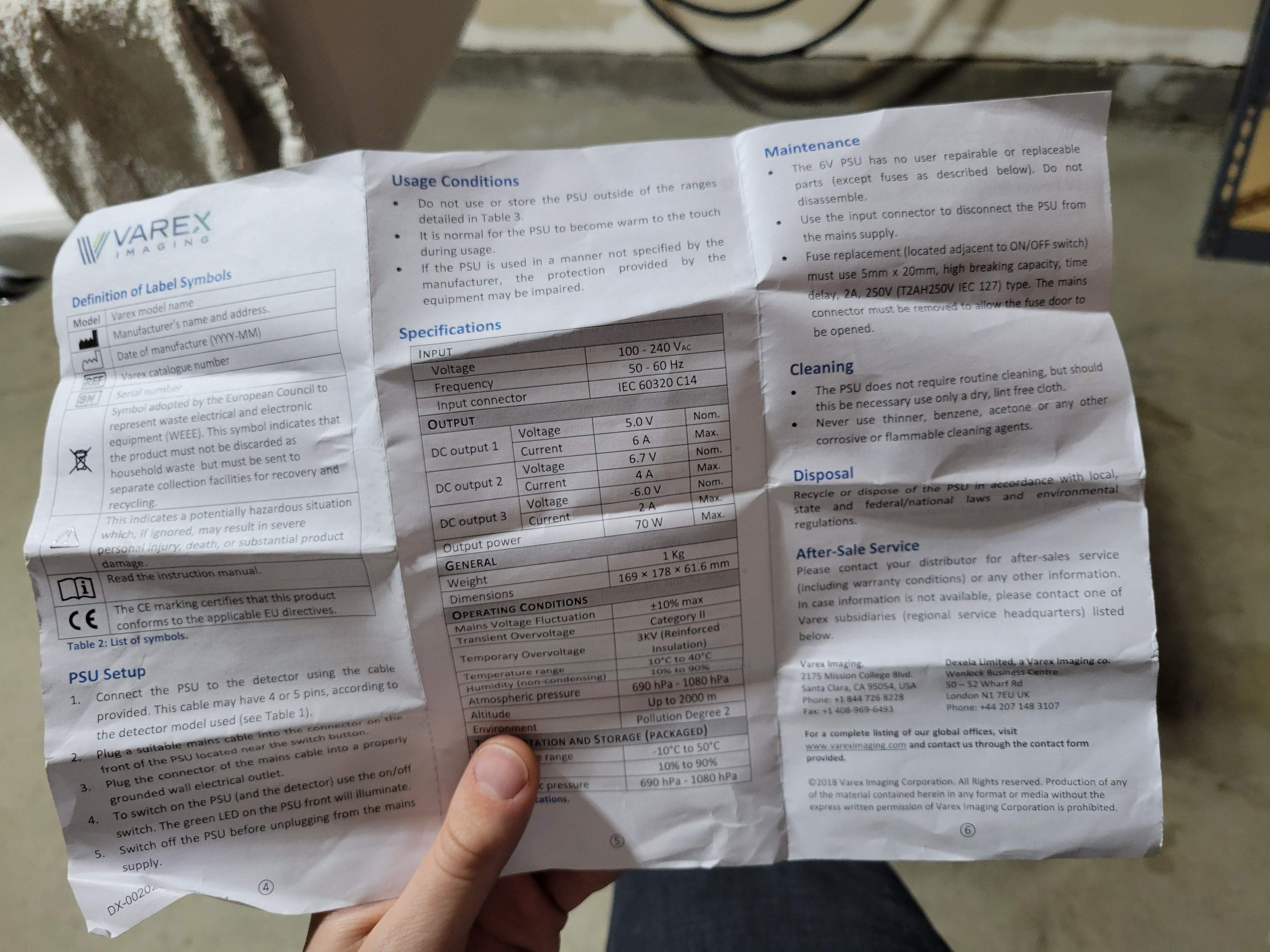
Well, is it 6 or 6.7 volts? WHICH IS IT? IS IT ACCOUNTING FOR A VOLTAGE DROP? Is my supply going to fry the detector? Ahhh!
A terrible cable would be necessary to find out:
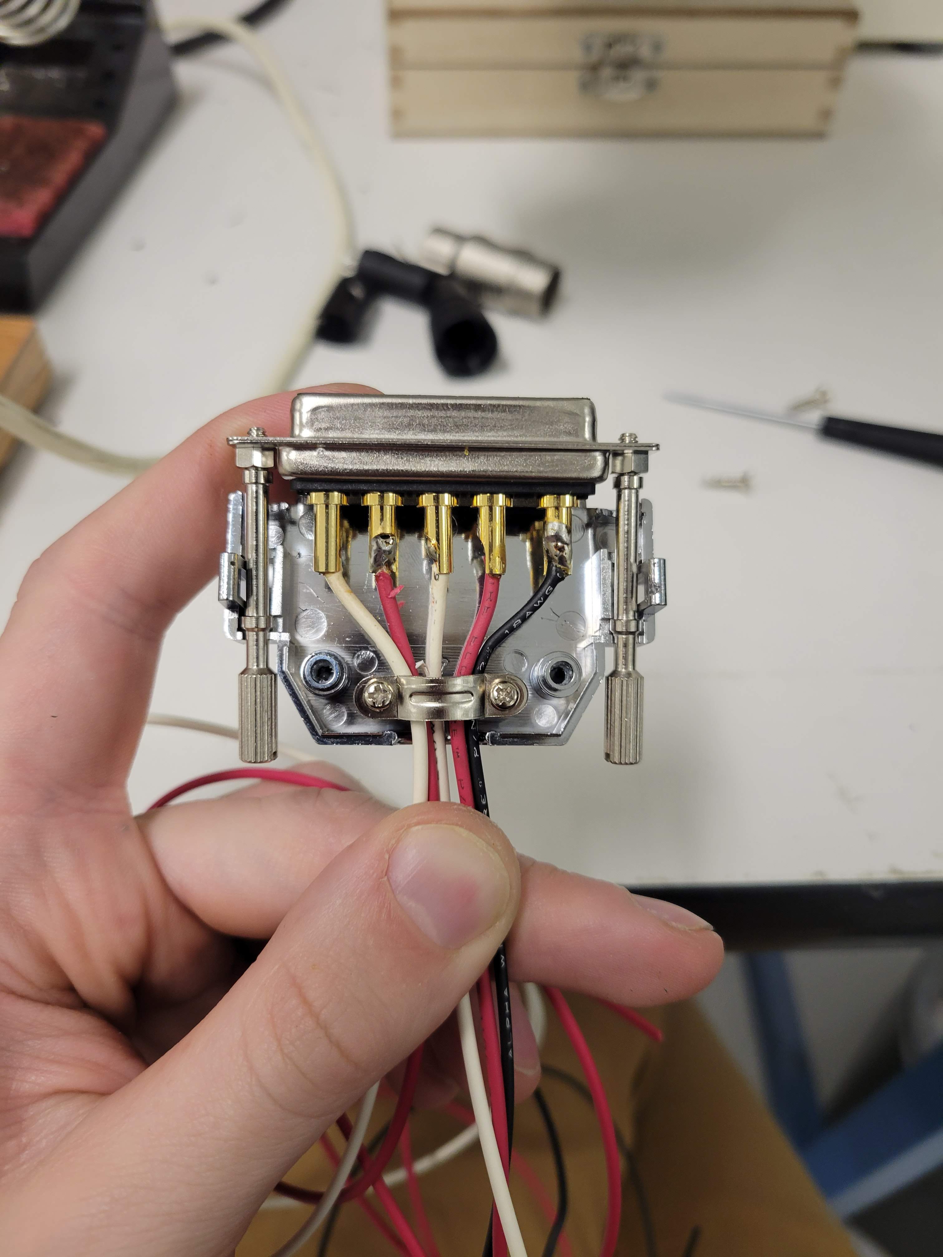
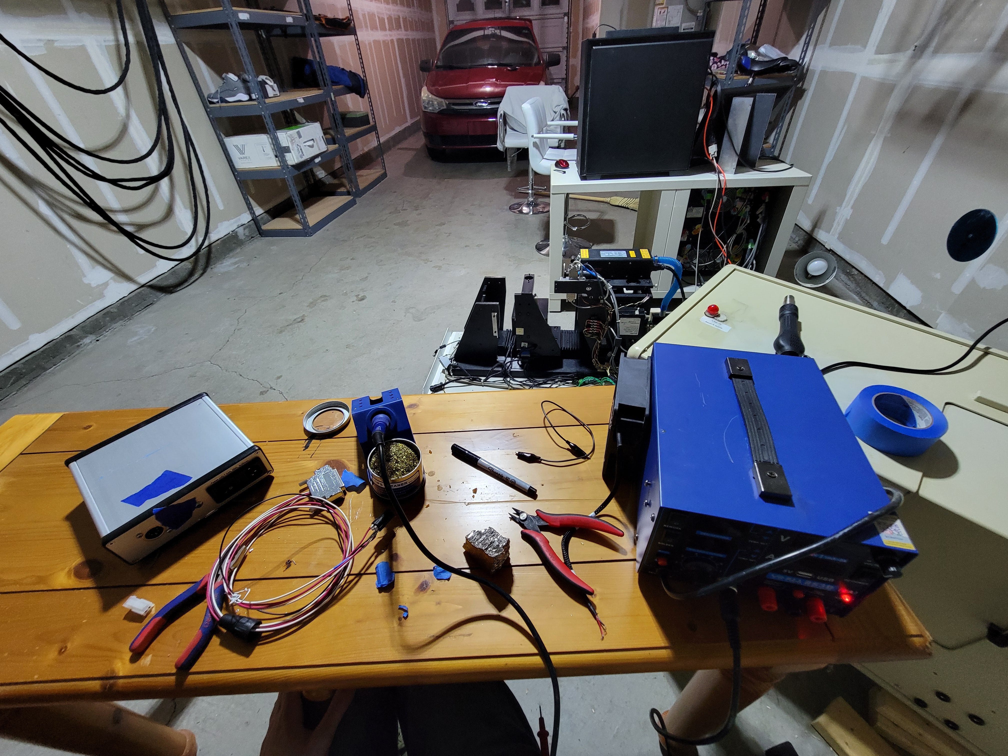
One end XLR, the other DB5. Snapshot of my Cavelike soldering environment:
Luckily, the detector didn't go POP when I plugged that supply in. Instead the fans went WHIRR. So I snapped in my secondhand donated (Thanks Misters G/B) Epix e8 framegrabber, plugged in my 2x camera link cables I had to buy (hundred bucks) after realizing that the ones that came with the detector weren't the right ones, and then spent hours fretting about how my detector was dead and I was screwed.
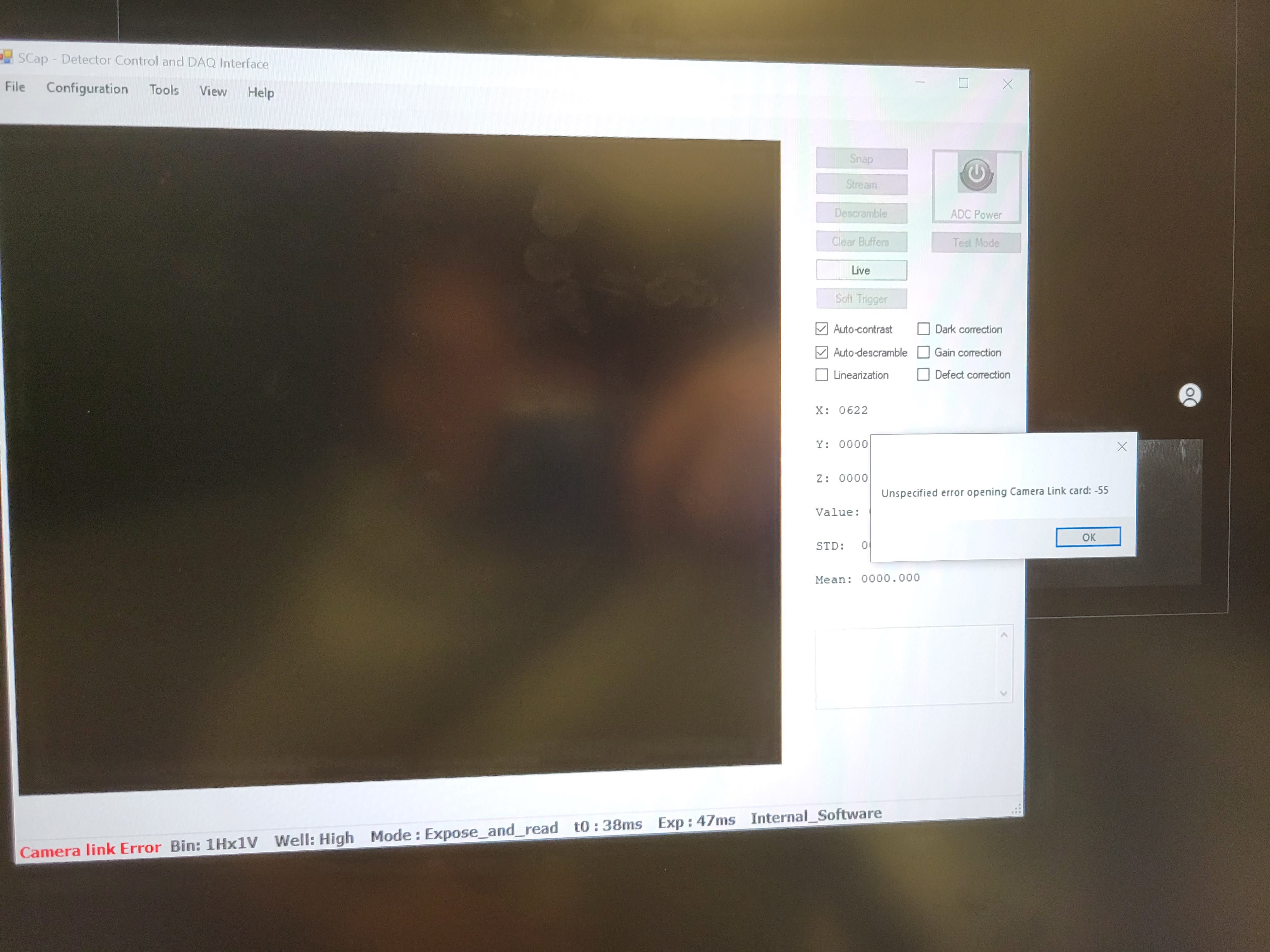 ...until I realized that it matters which ports the 2 frame grabbers are plugged in... and then WHAM!
A dark image! The panel is made of these 2 FPGA panels or something electronicy like that. And you can tell which model by the types of swirly patterns. Correcting for the constant dark image, and reboosting the contrast, gives an image of what the random shot noise will look like:
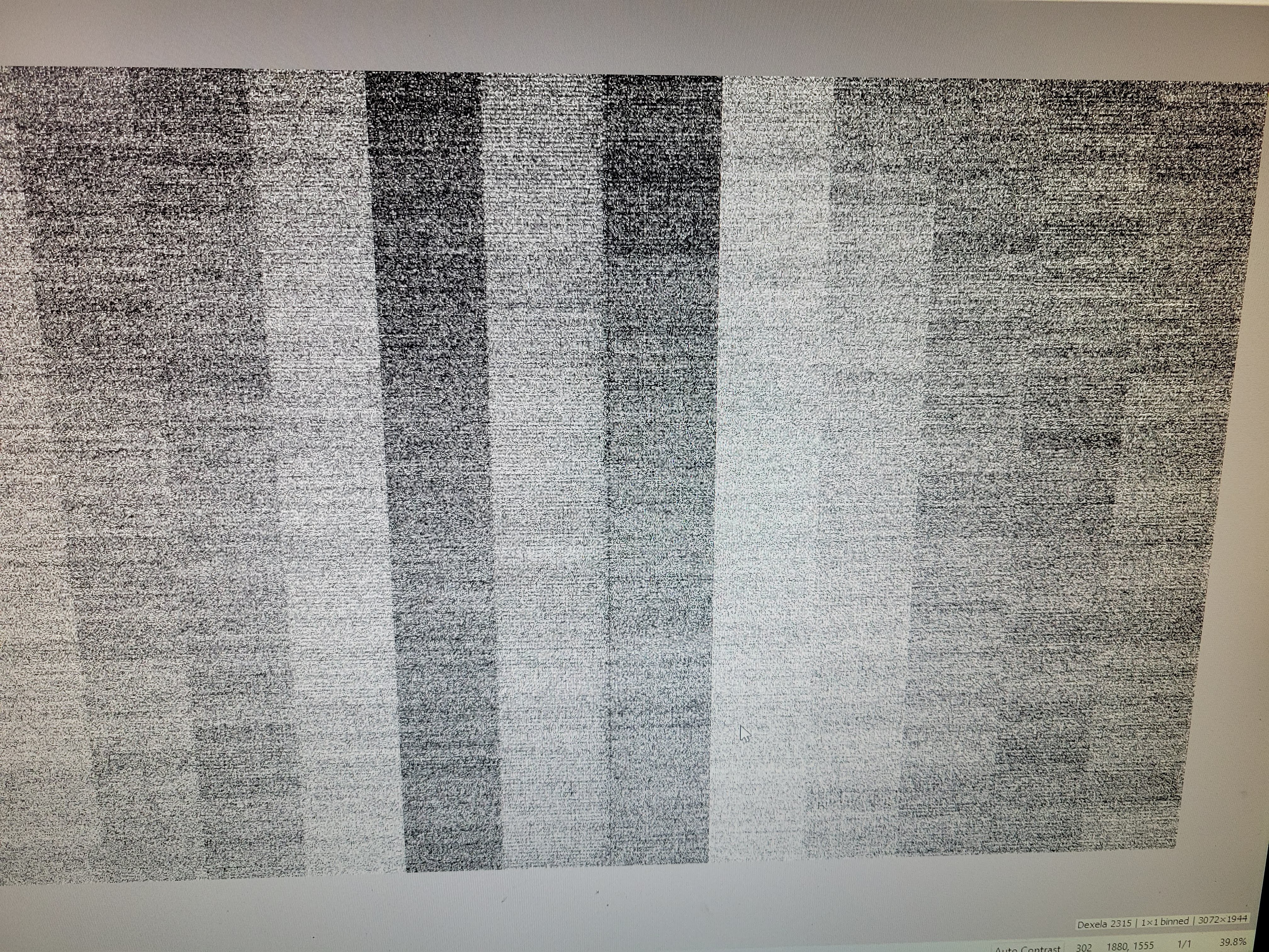
All very good stuff! Next time, we'll hopefully see some REAL images, taken with a working source if I haven't borked it today, and imaging the samples we really care about.
Discussions
Become a Hackaday.io Member
Create an account to leave a comment. Already have an account? Log In.
Great job Ahron, a lovely read as always!
Are you sure? yes | no