I've started to build a schematic of piezoelectric controller. I made schematic and layout. In my current version we use LM324N and it's quite old. We may switch to OPA4205 for better results. But for this version lets stay with the tested LM324N.

Made schematic/board of power supply board
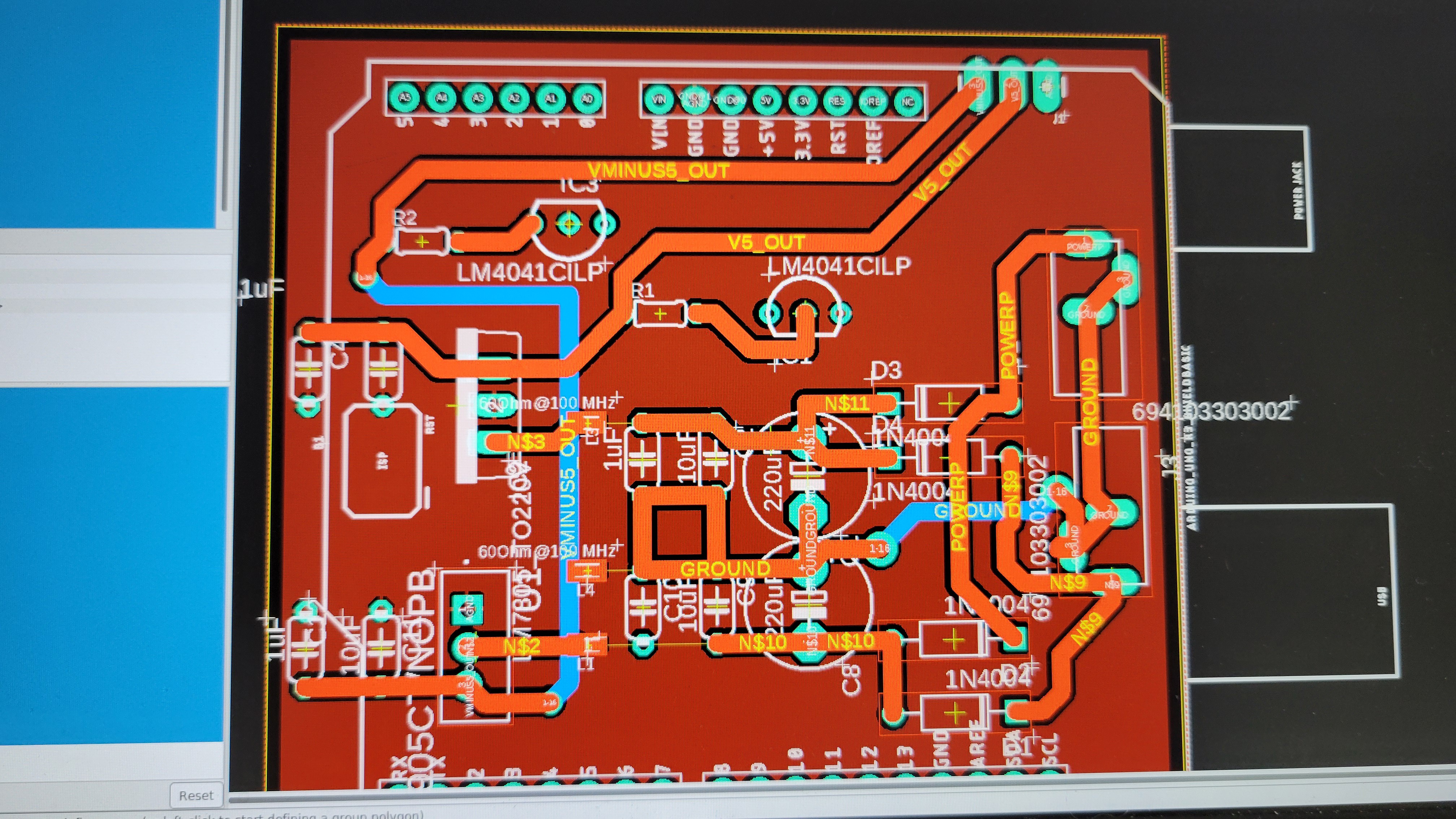
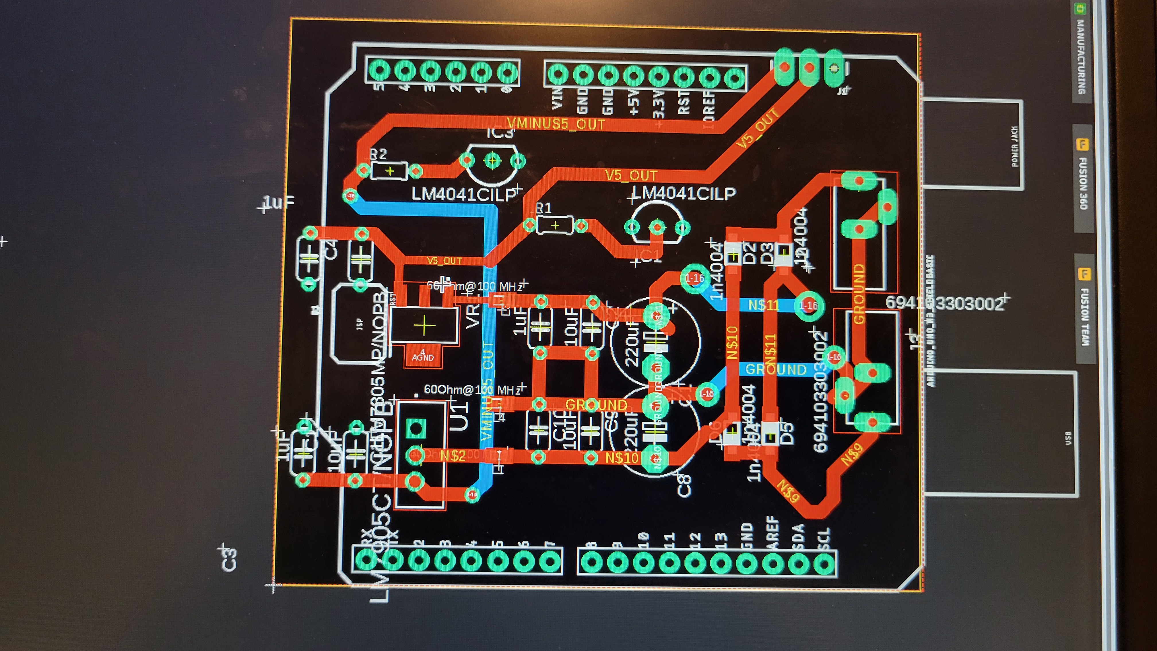
Luckily I've noticed that the power pins are switched between those two boards.
While fixing it, I've noticed that I use sime through hole components while most of the board are SMD (surface mounted device). The reason for that was to use the same components I've used in breadboard. Then the question rised do I have those components in SMD format?
Fortunately the answer is yes. I didn't buy those components I just got them while buying SMD resistors.
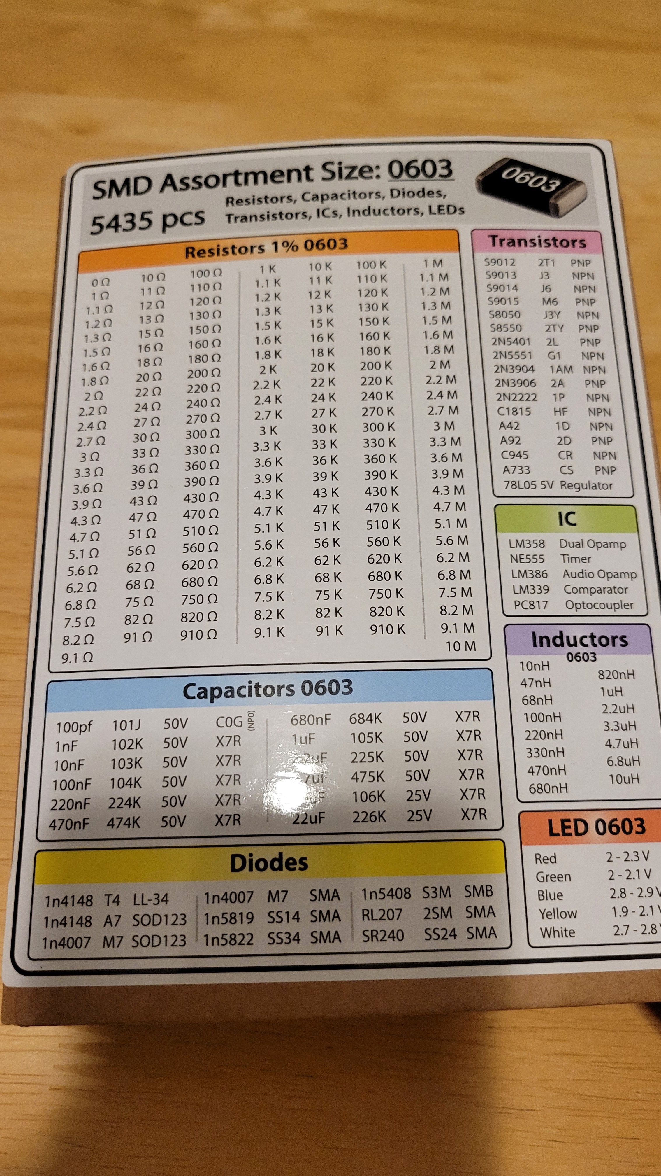
So I got diodes 1n4007 and lm339 comparator. Plus, I got 78L05 voltage regulator. Let's use those to make simple and cheap solution.
The new power board
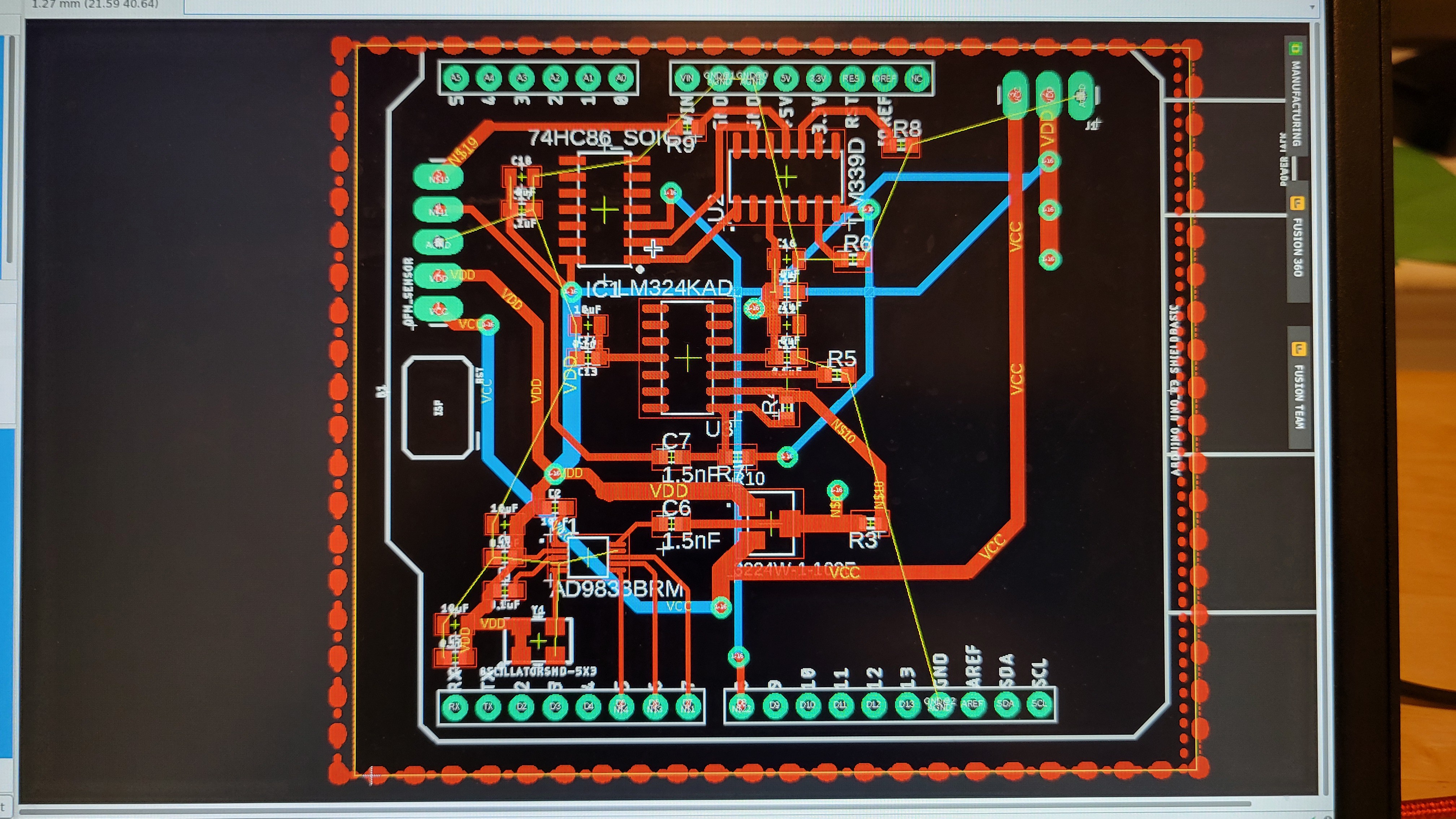
Made input board
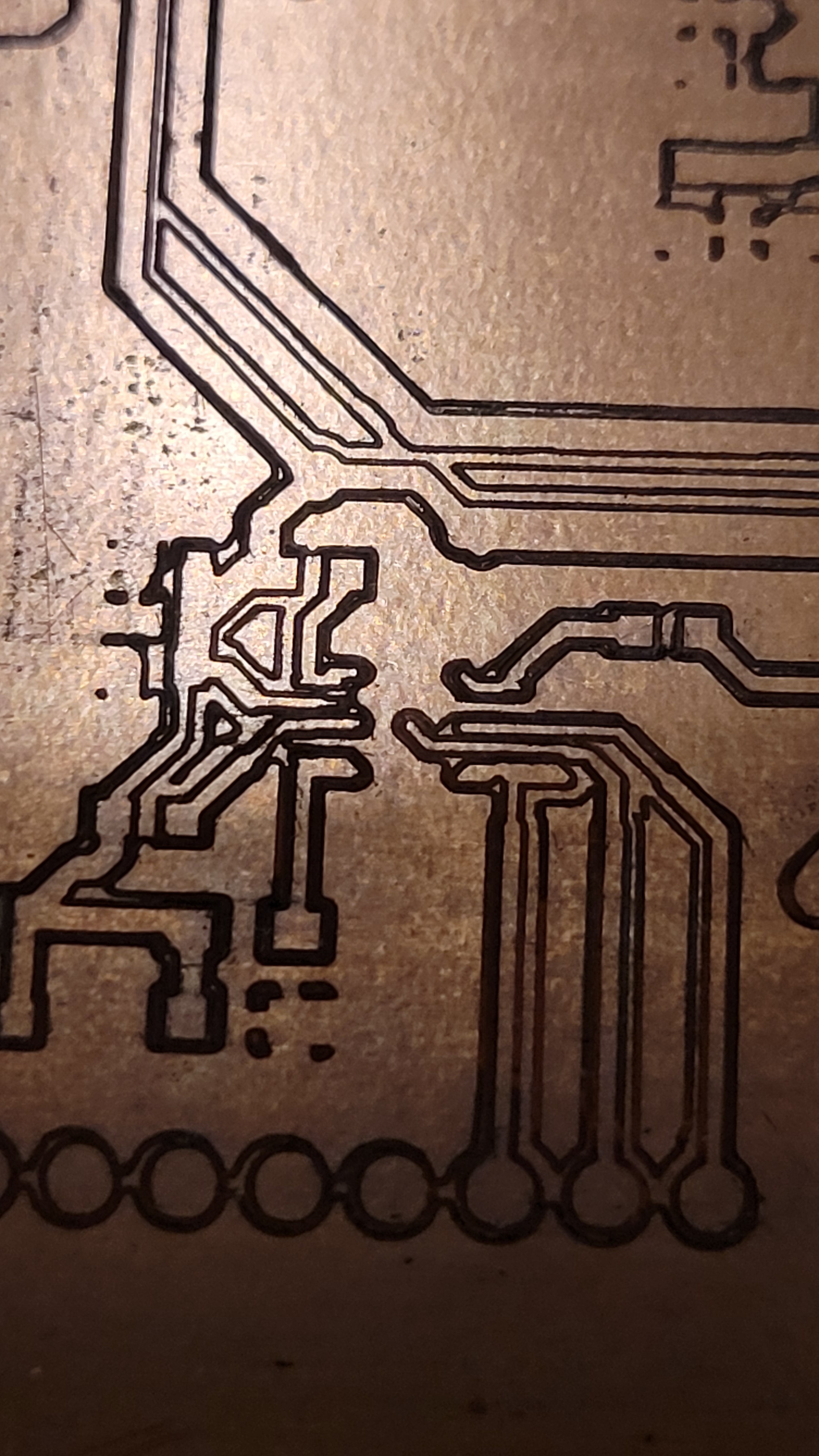
Started to create bare PCB boards using CNC, it took me at least ten attempts to get it right and learn all the tricks failing on each possible step.
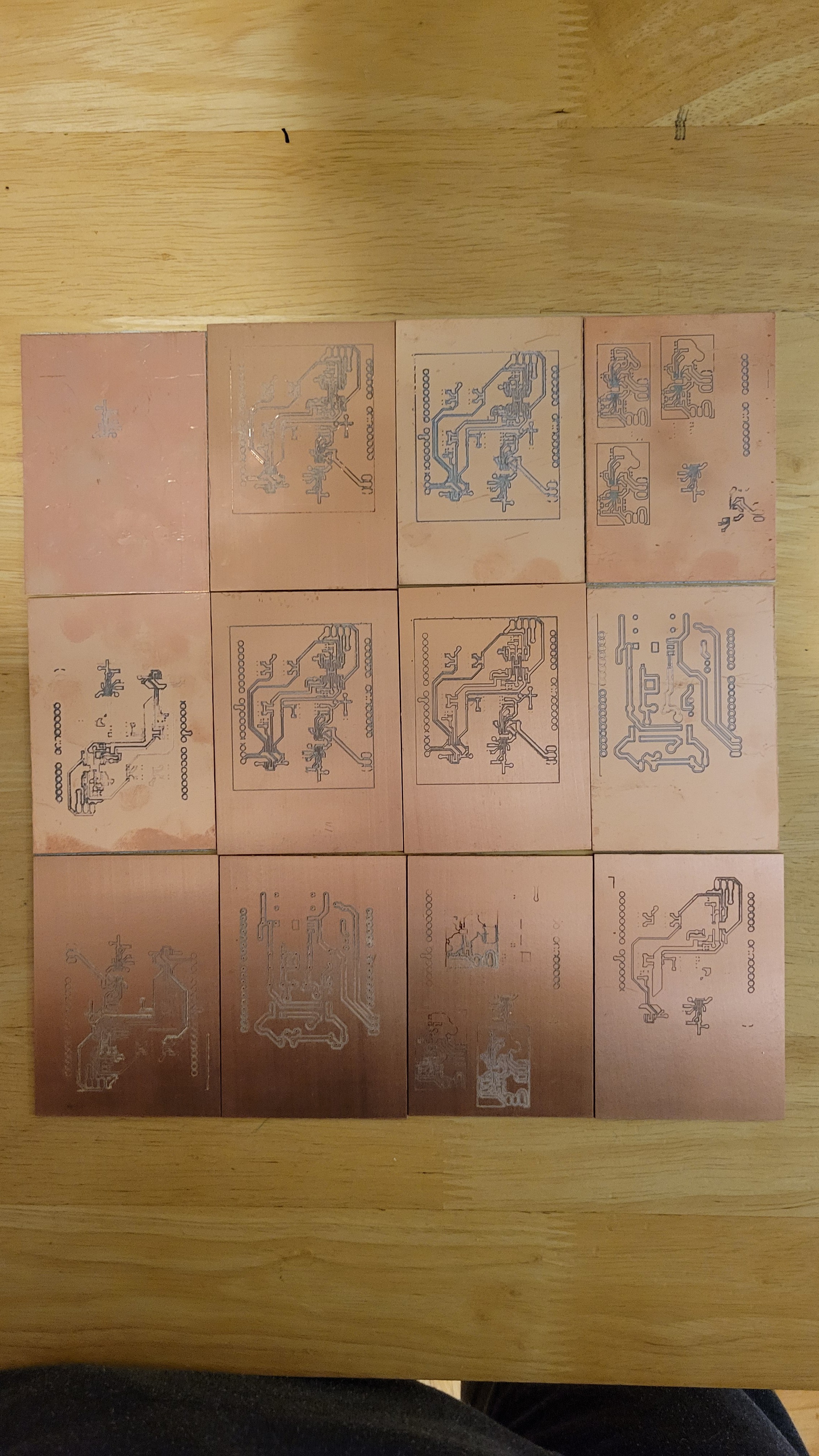
Luckily a pack of ten PCBs costs only six dollars. After few minor but important adjustments I got the desired result
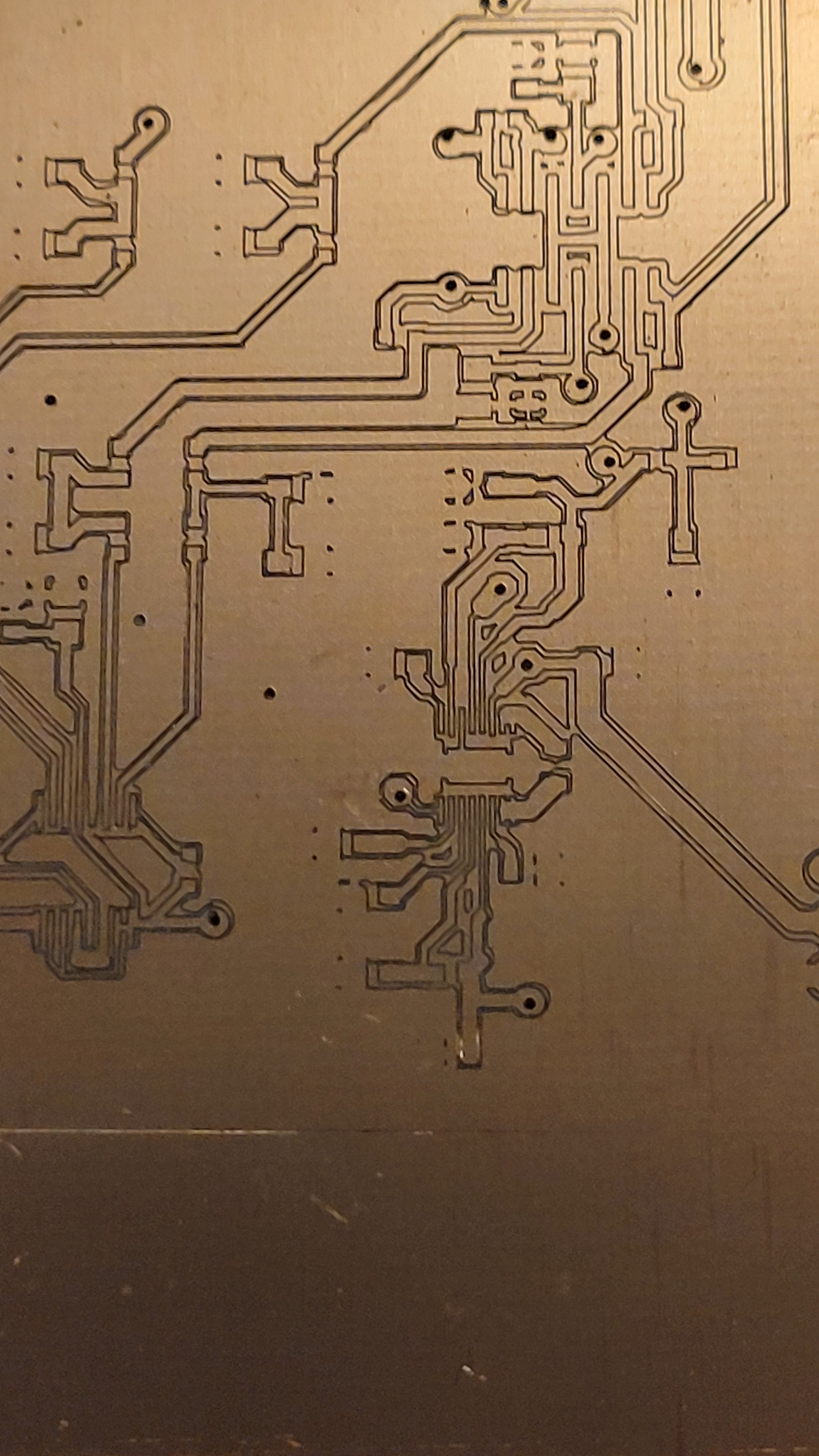
Suitable for 0.5mm pitch ICs.
One good thing about making your own PCBs is how fast you can fix things once they go south.
Here I made a mistake by moving the Arduino relatively to power output.(Although I don't remember doing it)
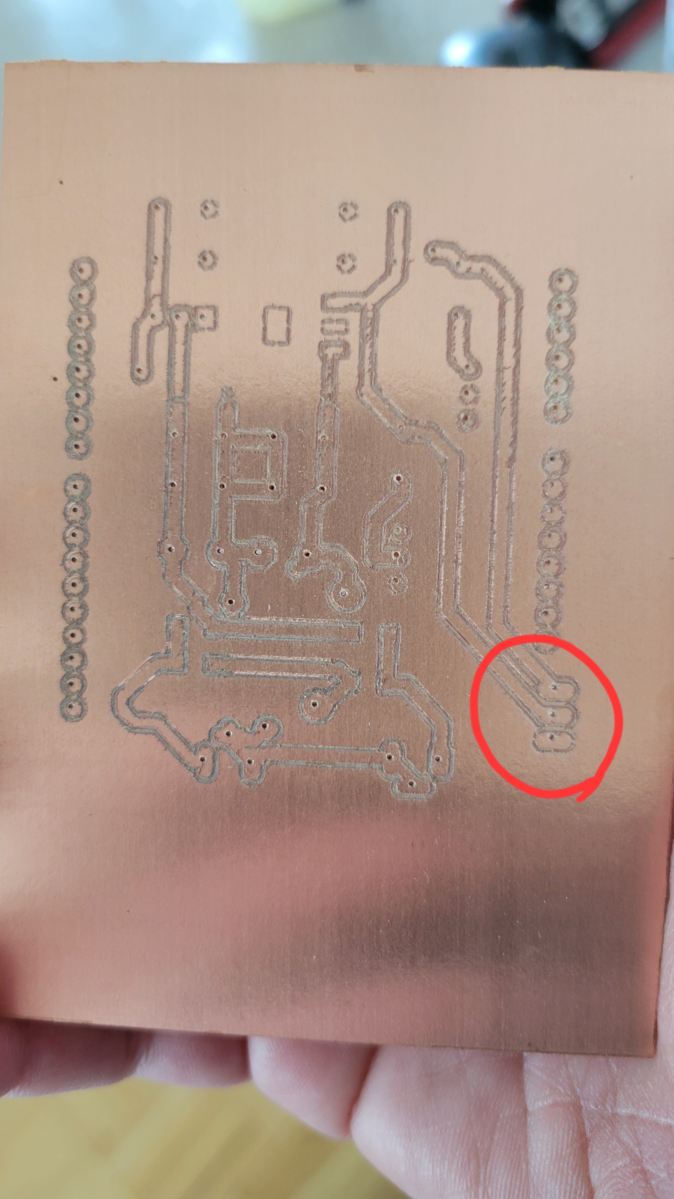
It took me few minutes to create a new one with the correction.
Now we can start populating those PCBs with components
Slowly but surely, started adding components
Rectifier bridge works!
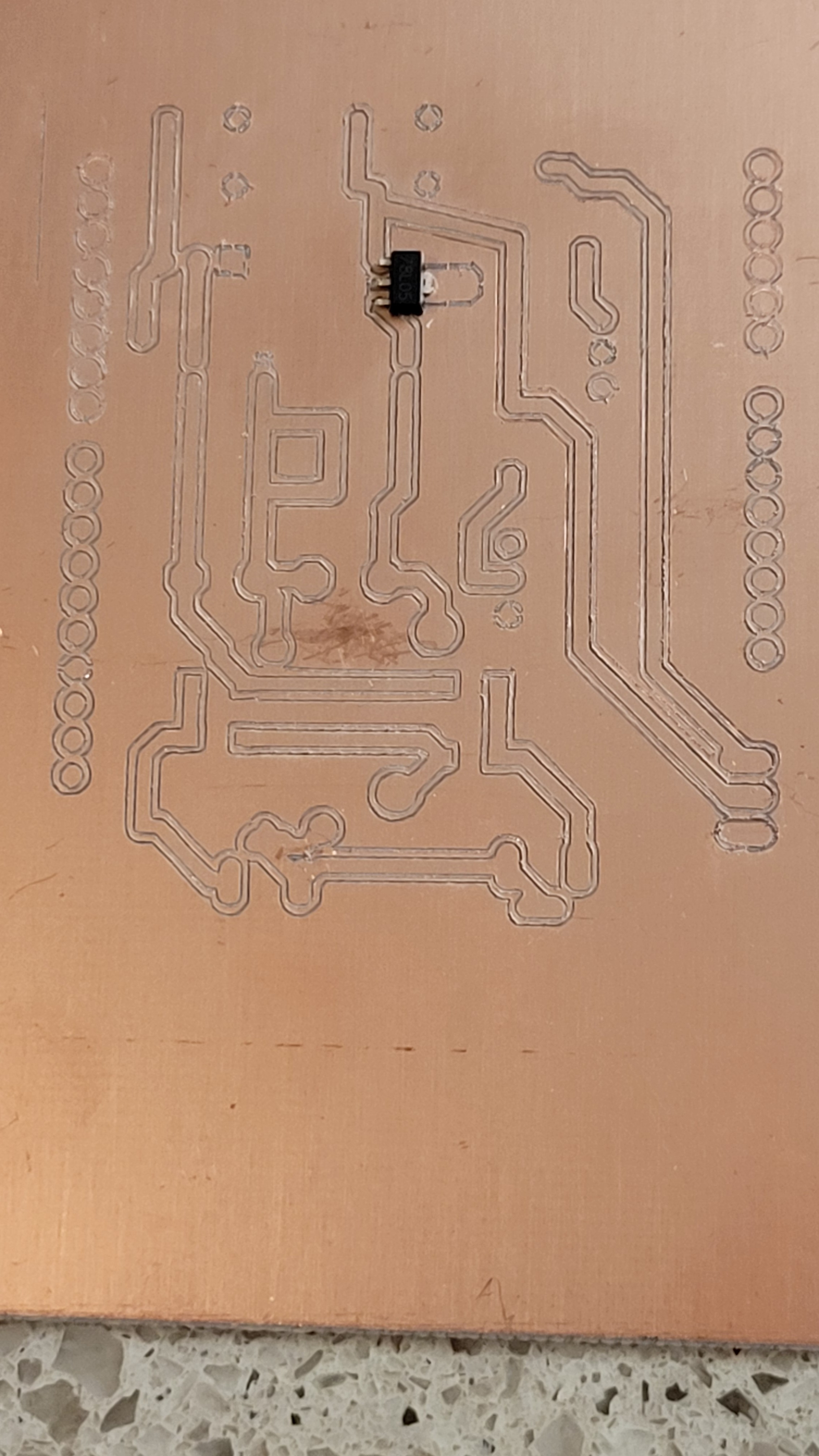
Added more components capacitors and L78L05 voltage regulator just to find that I used wrong layout much bigger with opposite pinout layout. Tried to reverse and make changes on the fly with Dremel. Ended up with bricked PCB. This should be the 'easy' one.
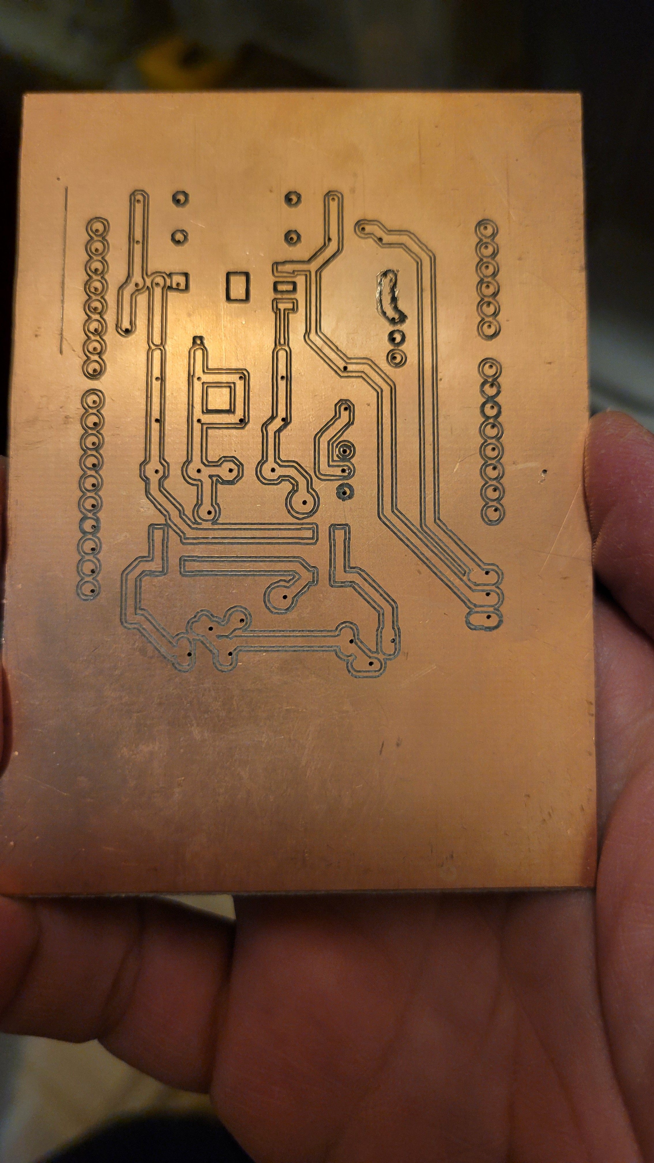
Luckily I can print PCB at home.
Ta-da!
It took me quite a while to be able to create 0.5pitch PCBs. I almost gave up...
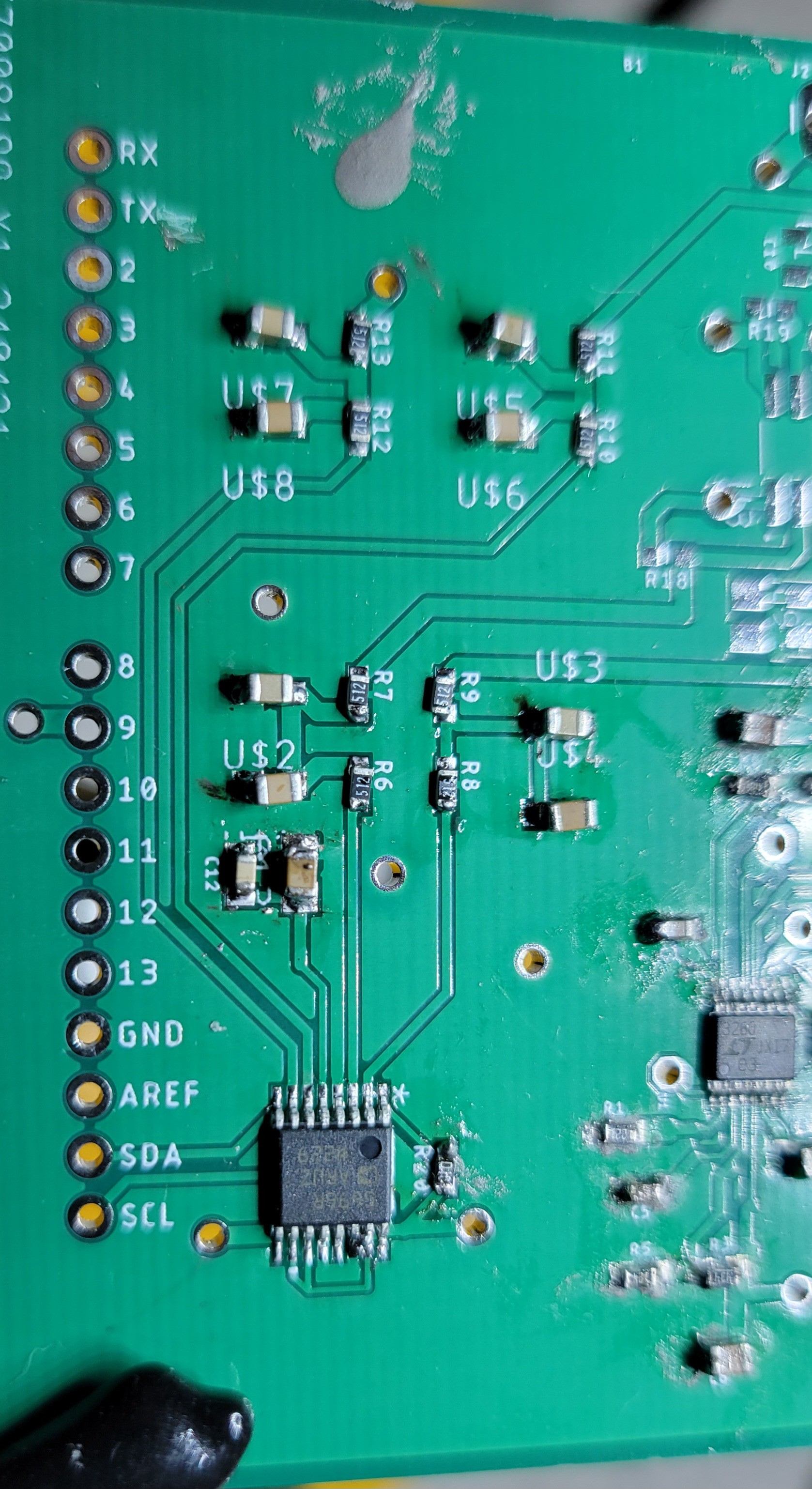
Ironically, I got my PCBs from China the same day I finally managed to create my own high quality PCBs. (I will tell it in another blog)
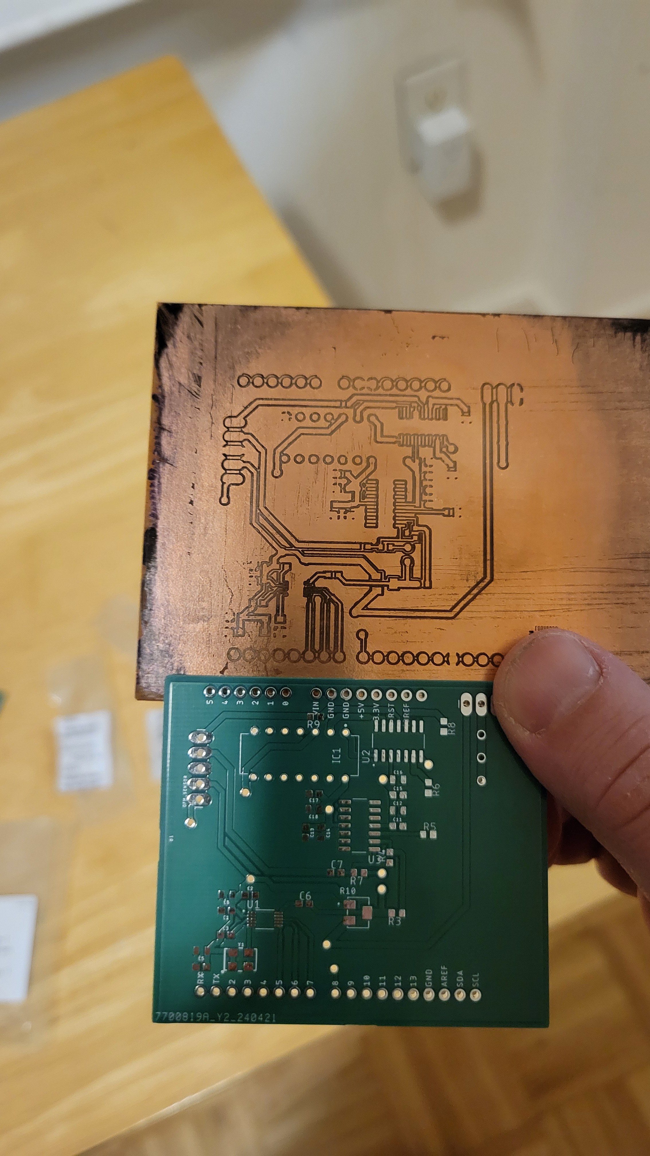
I must admit Chinese one looks much better :)
Anyways now we can continue 😃
* Added holes to power pcb,
* connected ac,
* Made rectifier bridge
* Added positive voltage regulator
Next negative voltage regulator
Got the positive and negative rails. How this song goes 'although I am not the prettiest thing you ever seen but I got my moments' 🤩
Finished with power supply PCB.
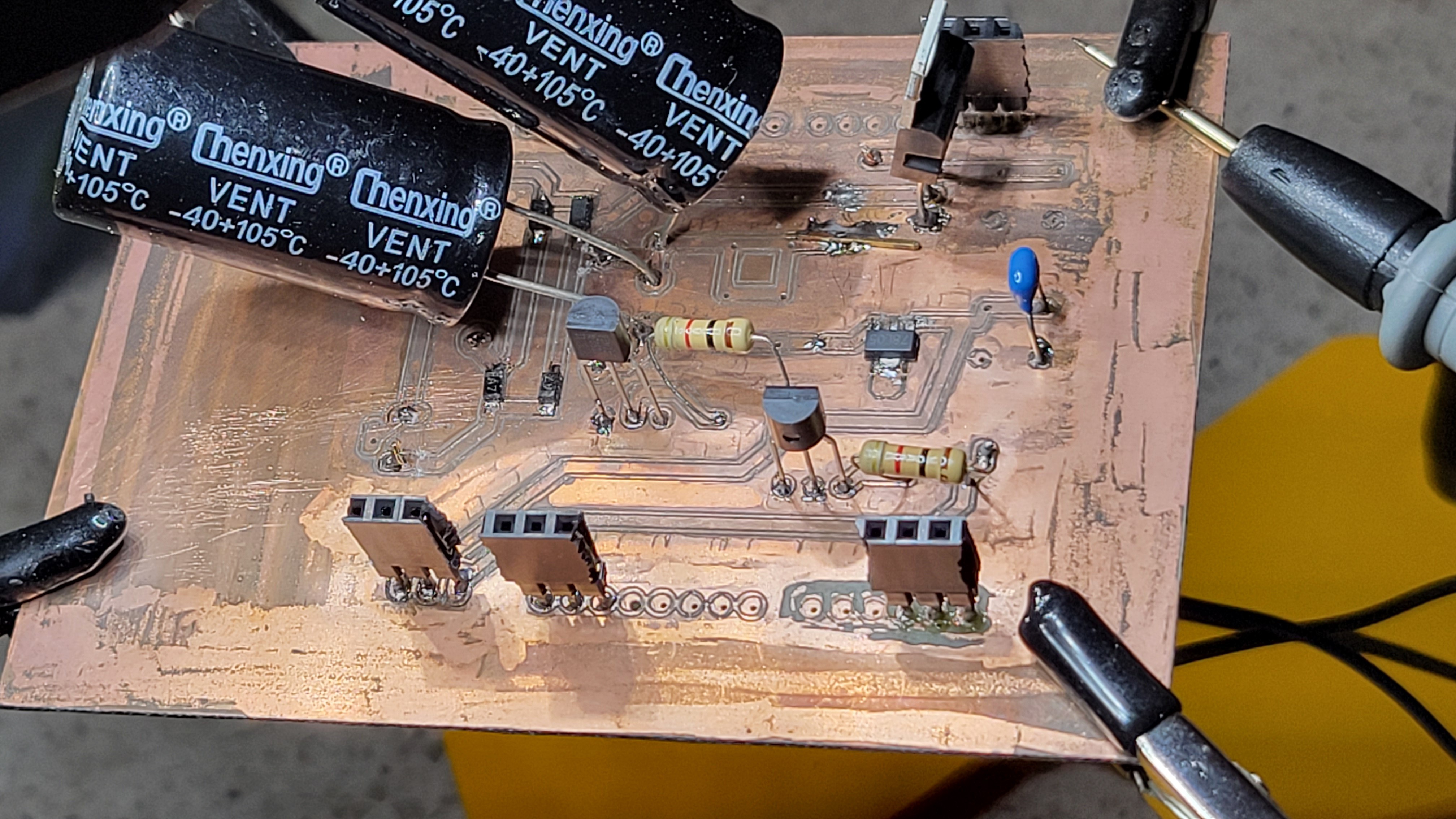
Started with piezoelectric controller, the hard part is charge pump. I didn't check it as it became too late

I must admit it much easier to work with a board that has solder mask and you don't risk of short-circuiting every component.
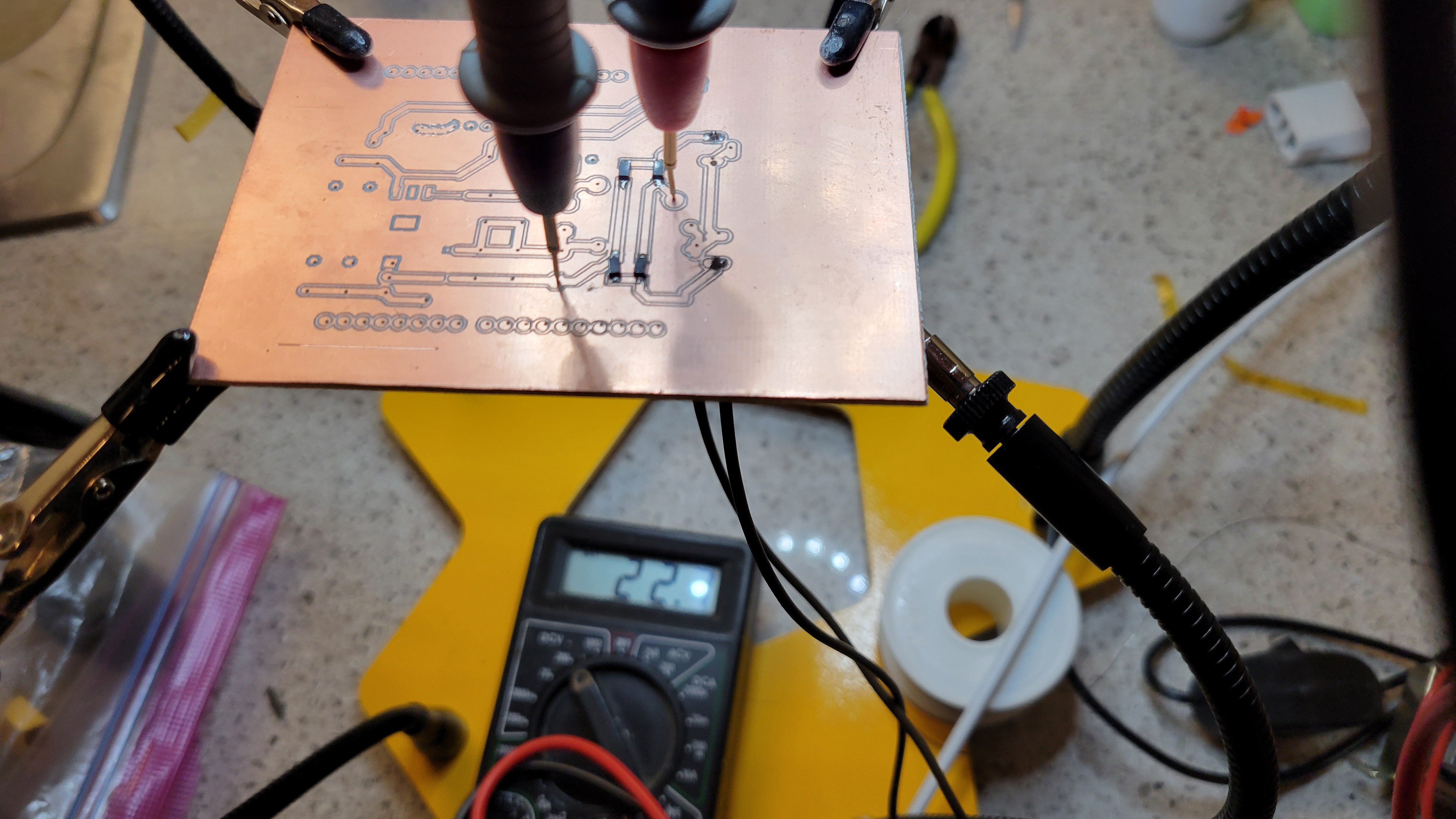
After checking the circuit it seems to be functioning as intended. Which was total surprise since last time it was such a pain in the neck.
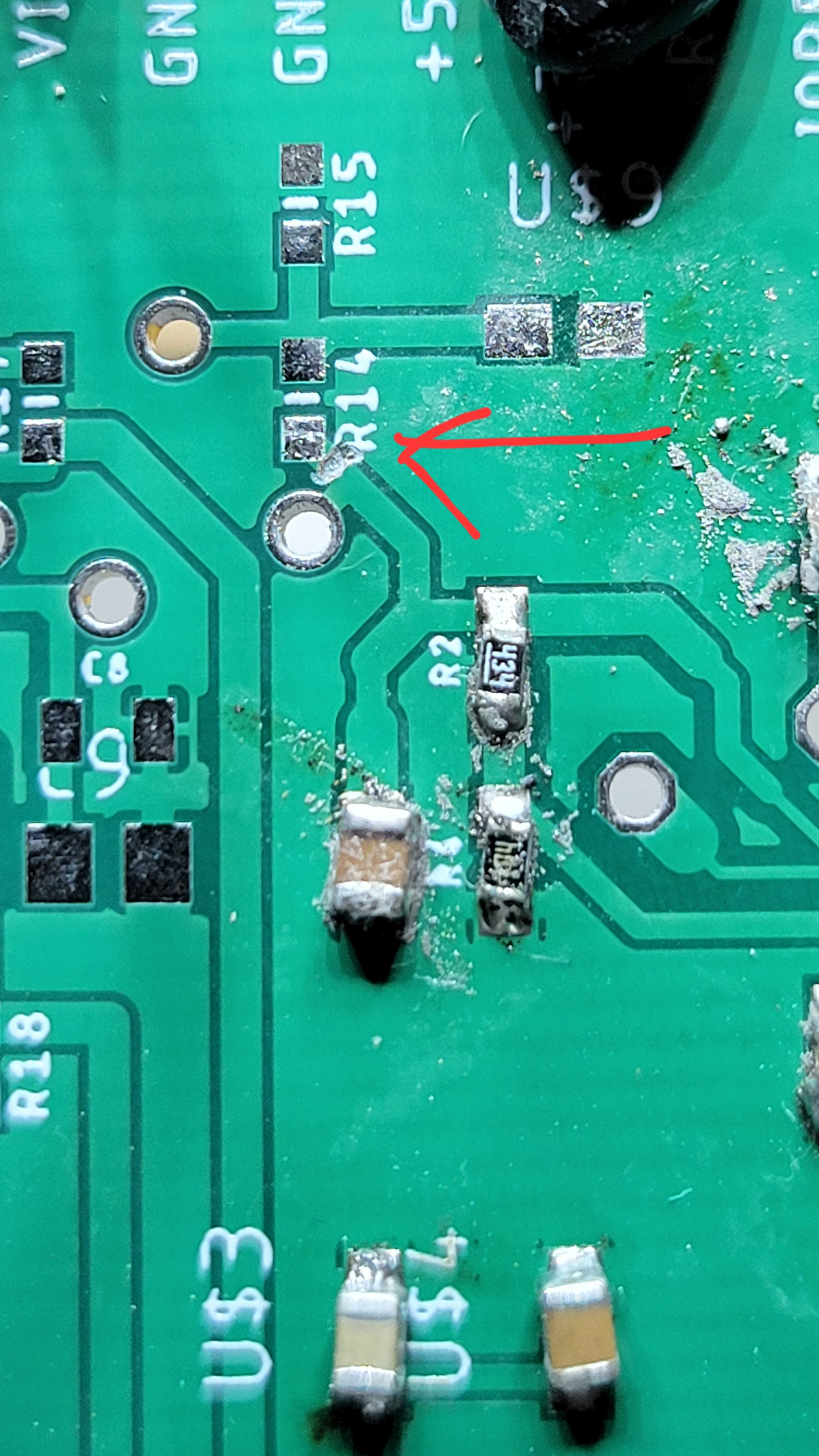
Added DAC and fixed some design issue I had(forgot to add address pins to the ground)
Bad news I've just realized that my reference voltage is from charge pump instead of 5v. I hope I could make some fix on the spot. Otherwise another two weeks to wait.
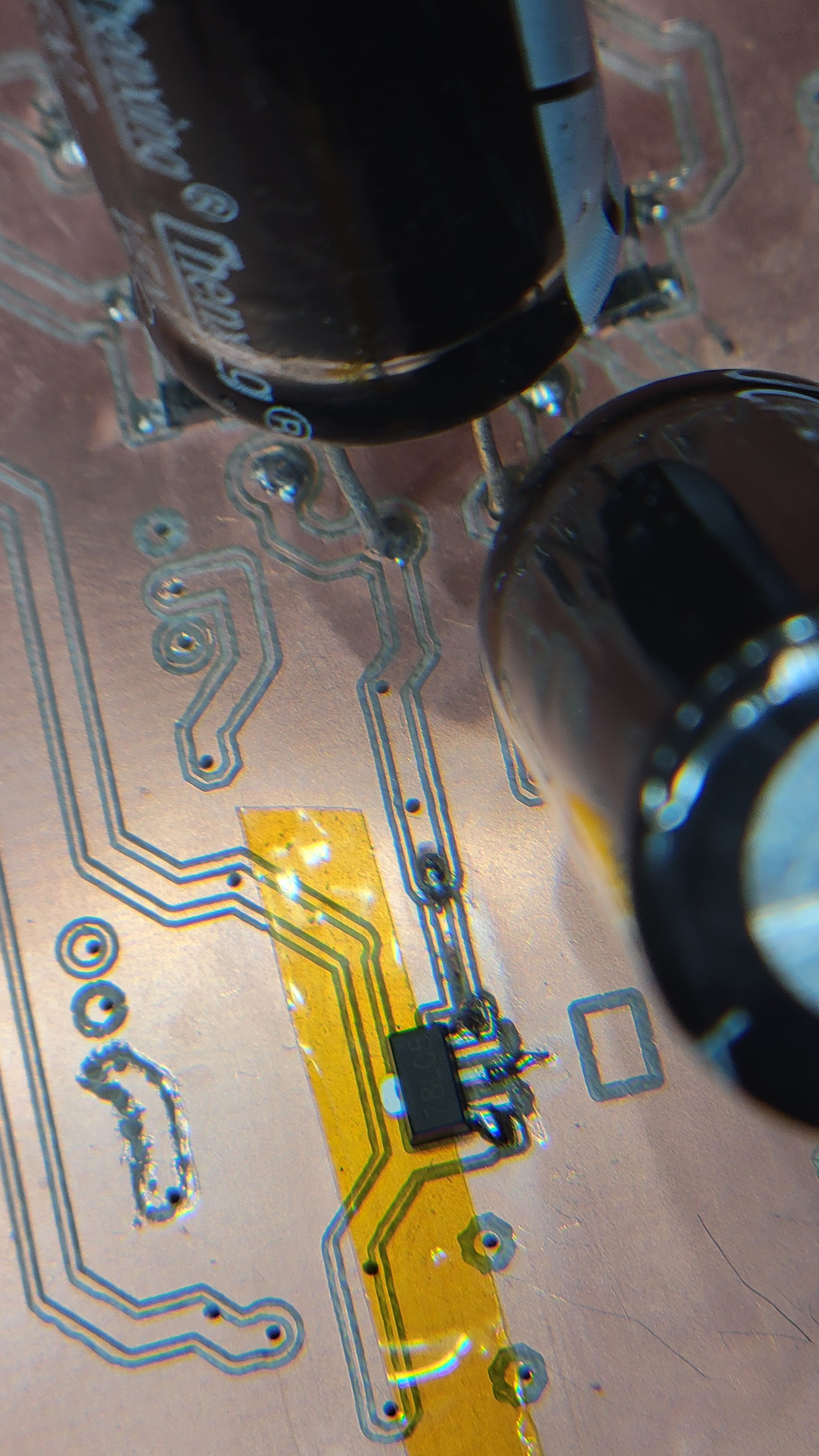
I felt like checking if DAC is working with all this unpredictable changes. Once I tried to connect I found that it doesn't fit
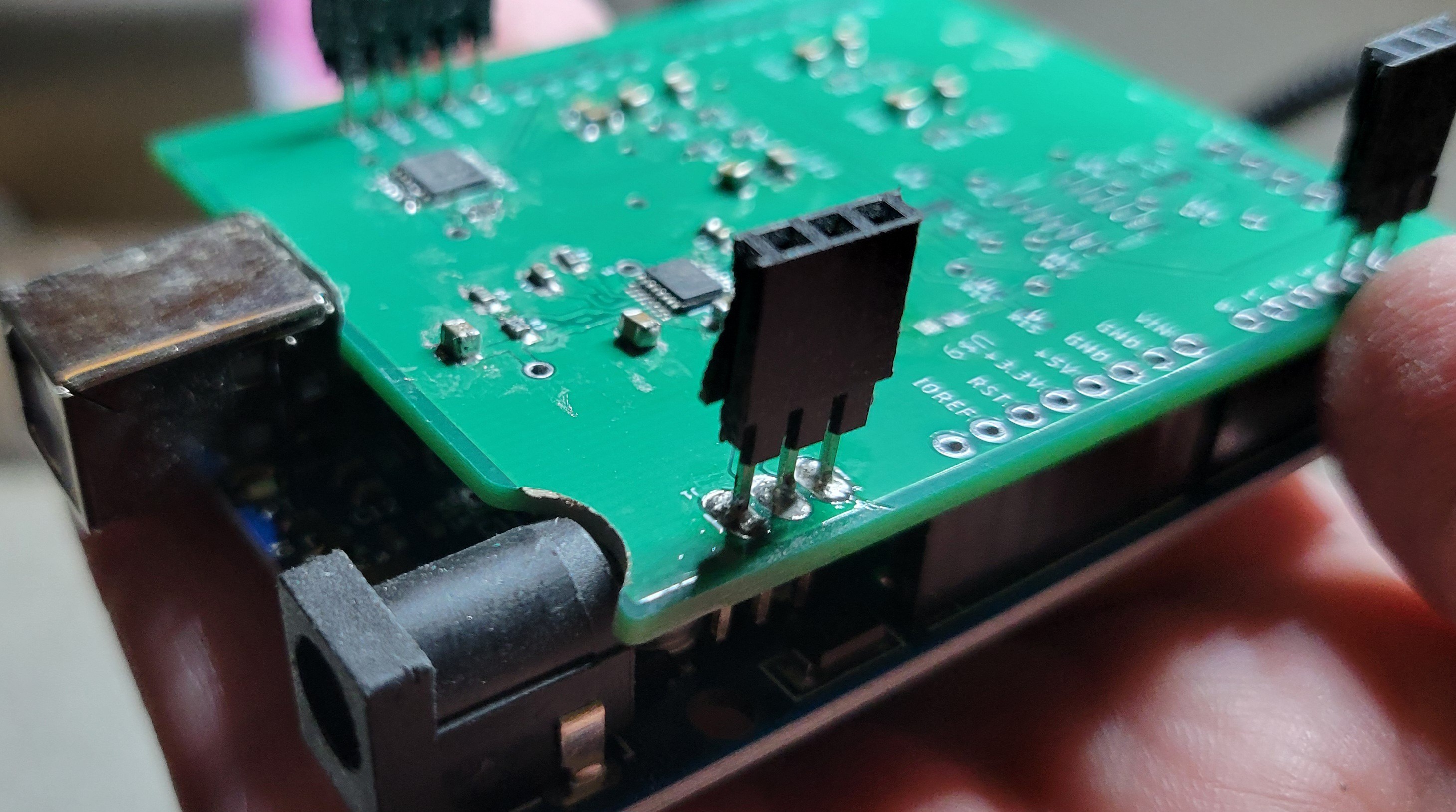
Luckily there are no components and I could carve away some PCB. Testing it I found that 3of4 pins are working (one is needs to re-solder but it's mild problem)
So it just works! I was surprised in a good way.
Gently I cut the wrong connector with Dremel.
But then I've discovered that my charge pump is not giving me negative voltage. I really wanted to avoid it...
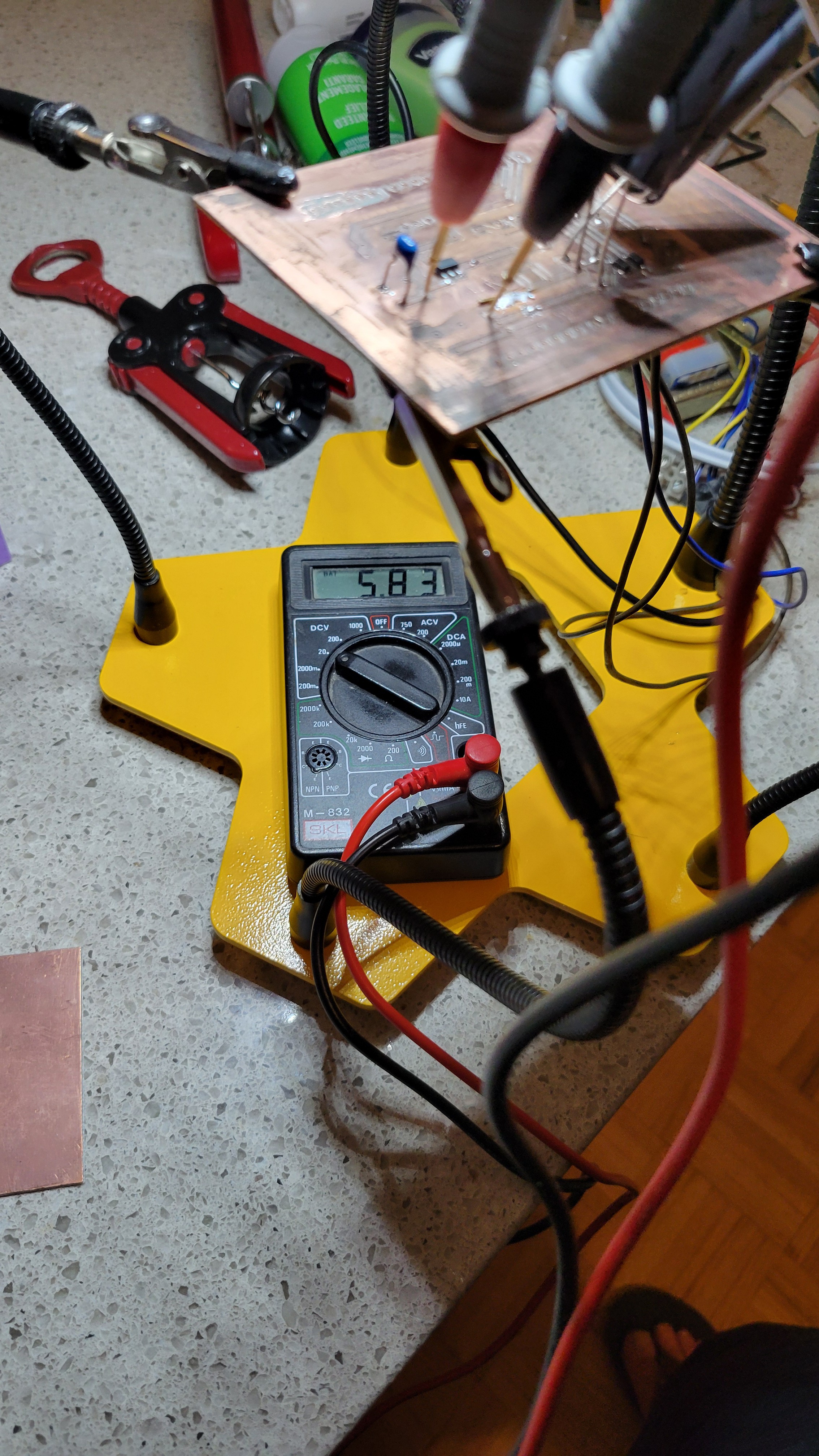
After re-soldering LTC3260(charge pump) it gave me negative rail but only 6 Volt. I thought charge pump could rise the voltage but from documentation it looks like it cannot go higher than input voltage. It's another fix I should do, nevertheless we can proceed and say we finished with this board for now
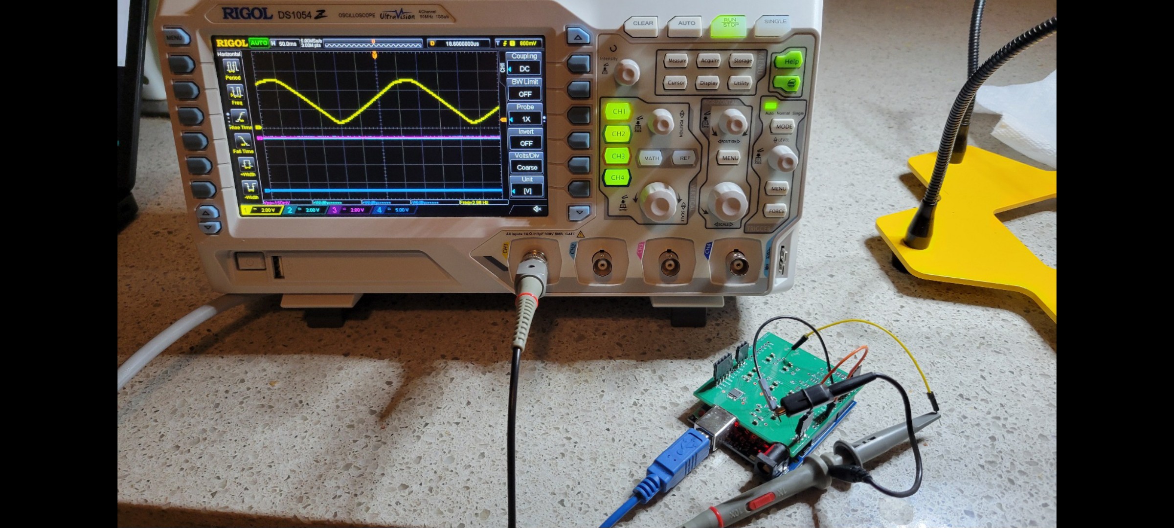
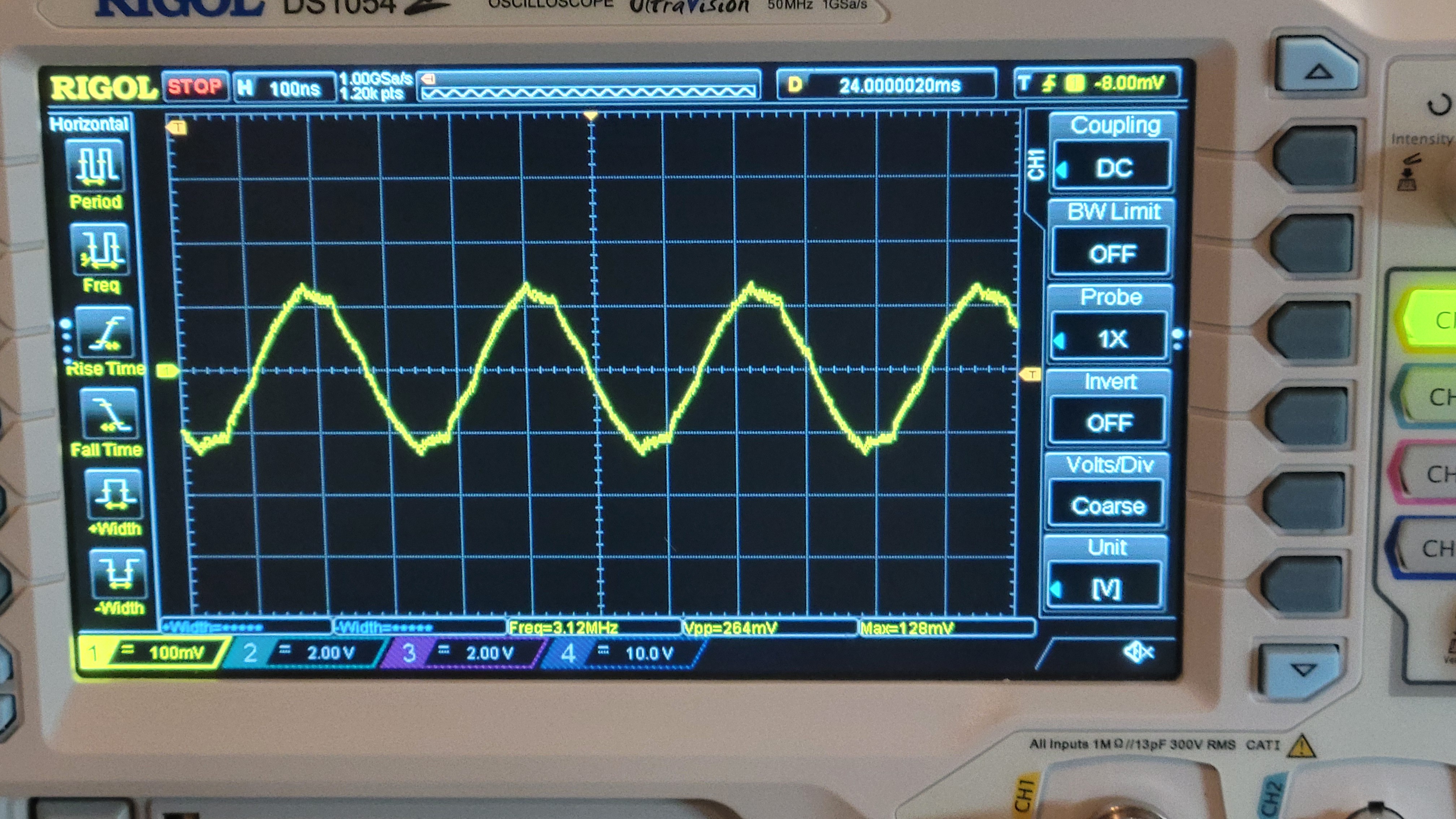
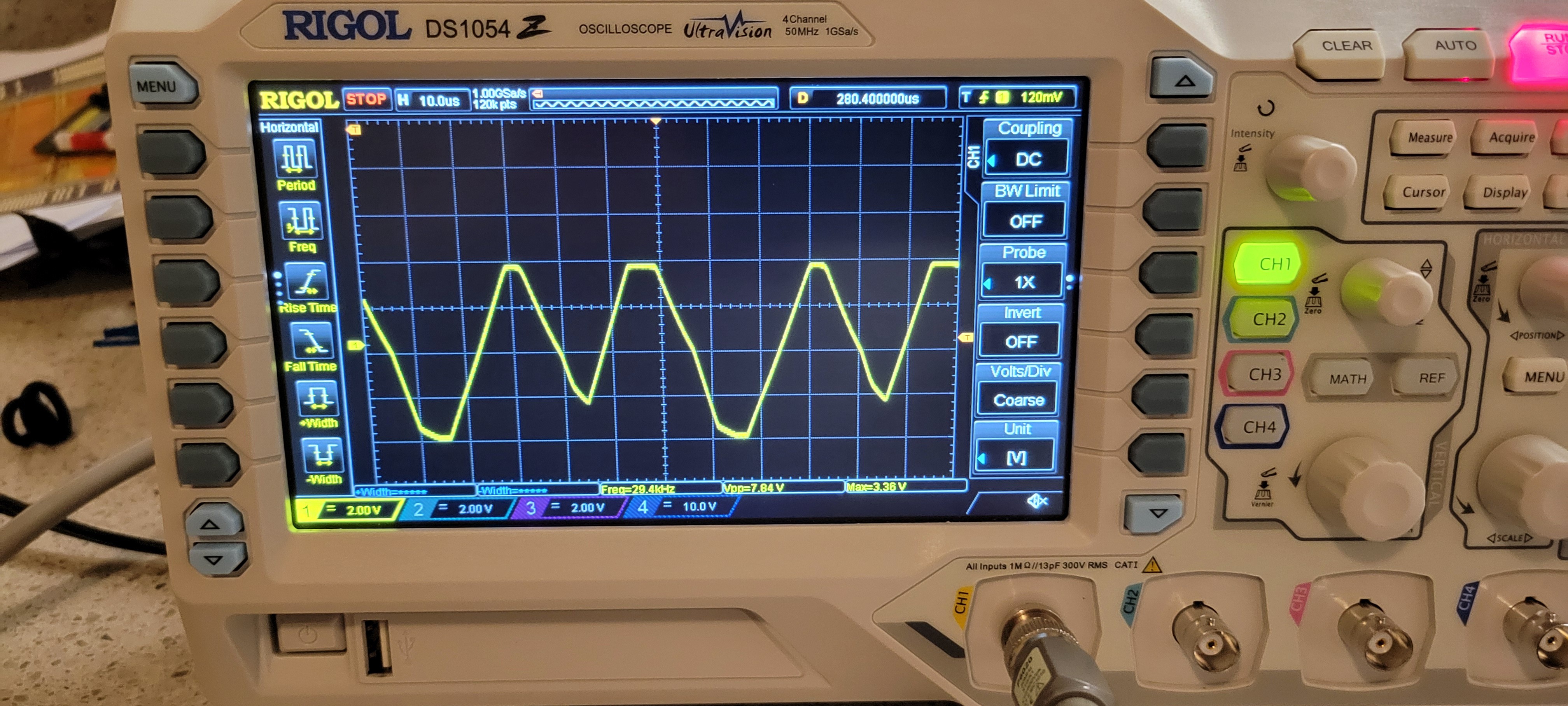
And the signal for four channels
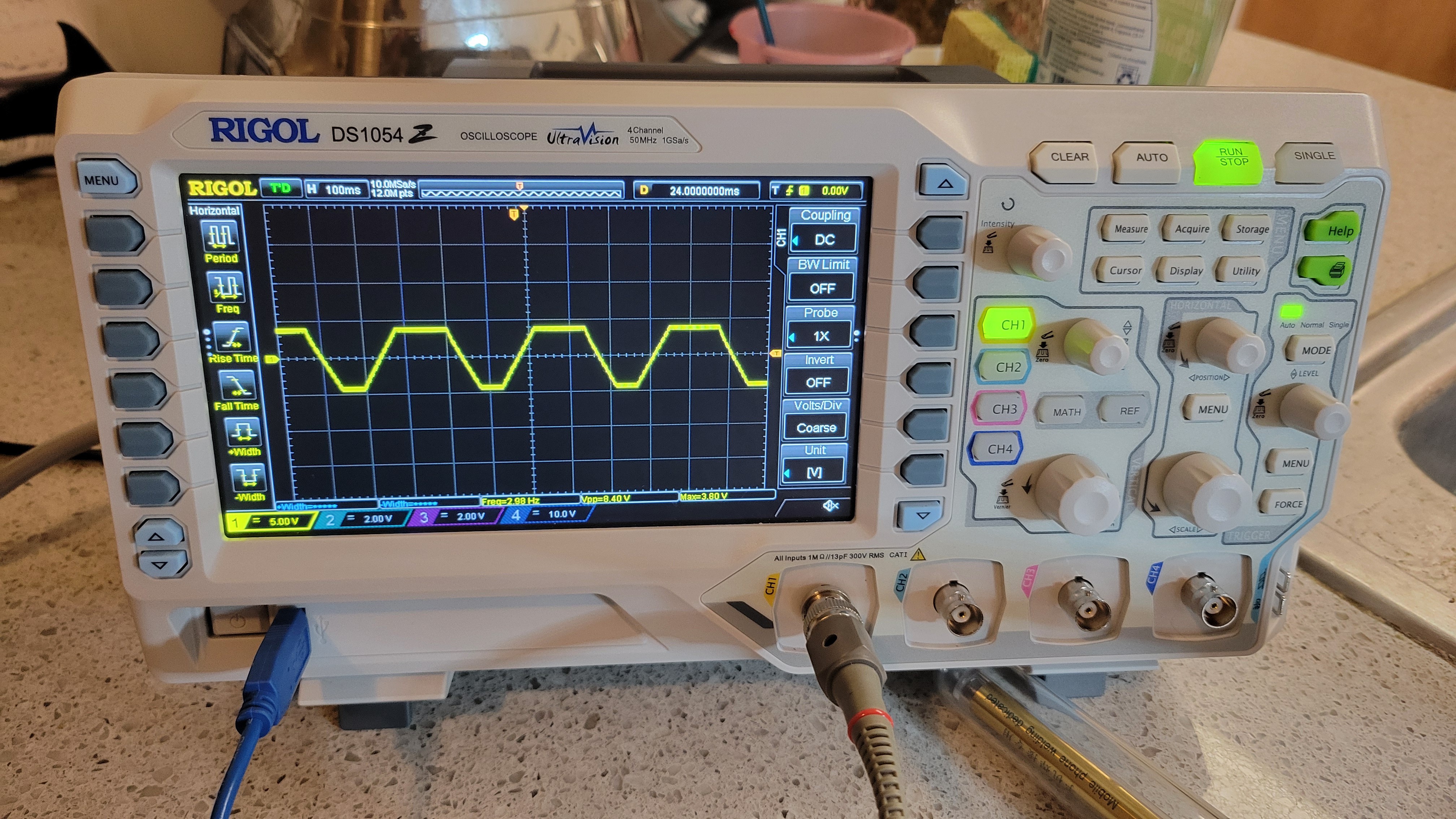
It's upper and lower part truncated because of;324 opamp low voltage(of 12v instead of 30v). For now I can fix it programmatically by using only part if the full range.
It's good enough for now until I will apply all the fixes.
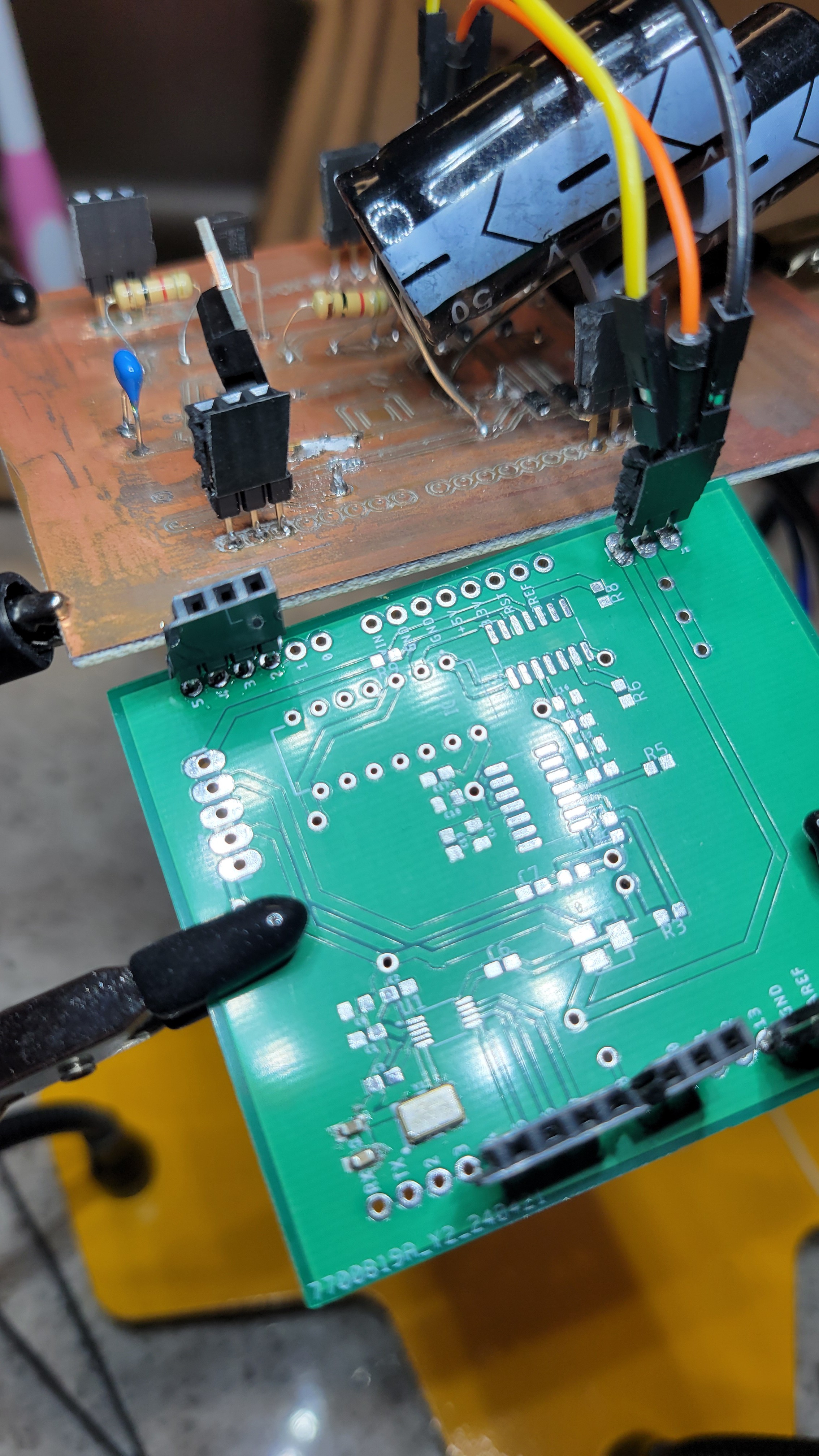
So... I have QFM module board, power supply board Peizzoelectric controller board. Now it's time for the last one... The input board (the one that generate signal for QFM module and reads QFM output)
Input board have mainly three parts. First is was connecting clock for AD9833(signal generator) Second connect AD9833 and be able to control it via Arduino. Third and last part is phase detector.
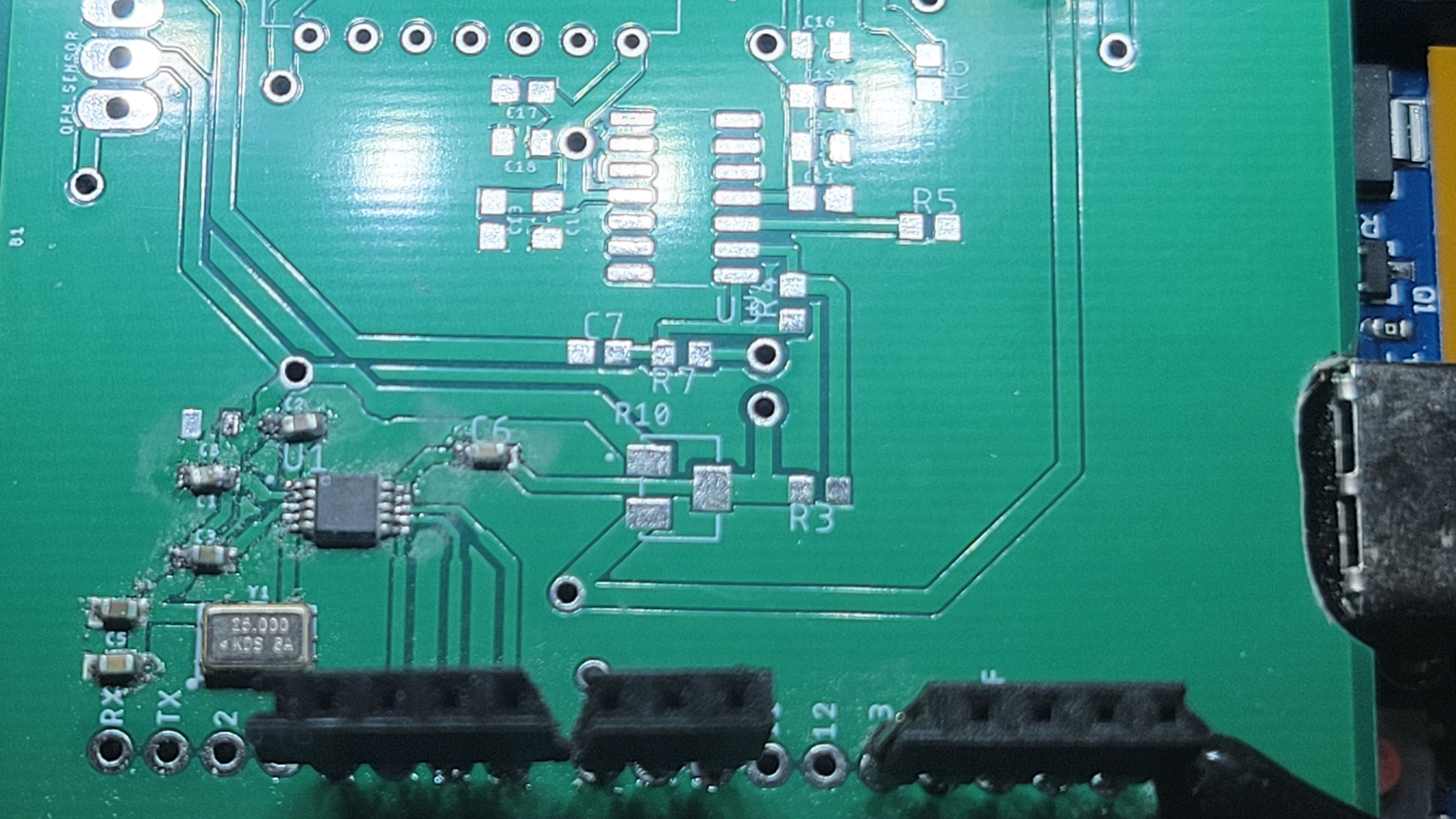
Here is the first part
And generated clock signal
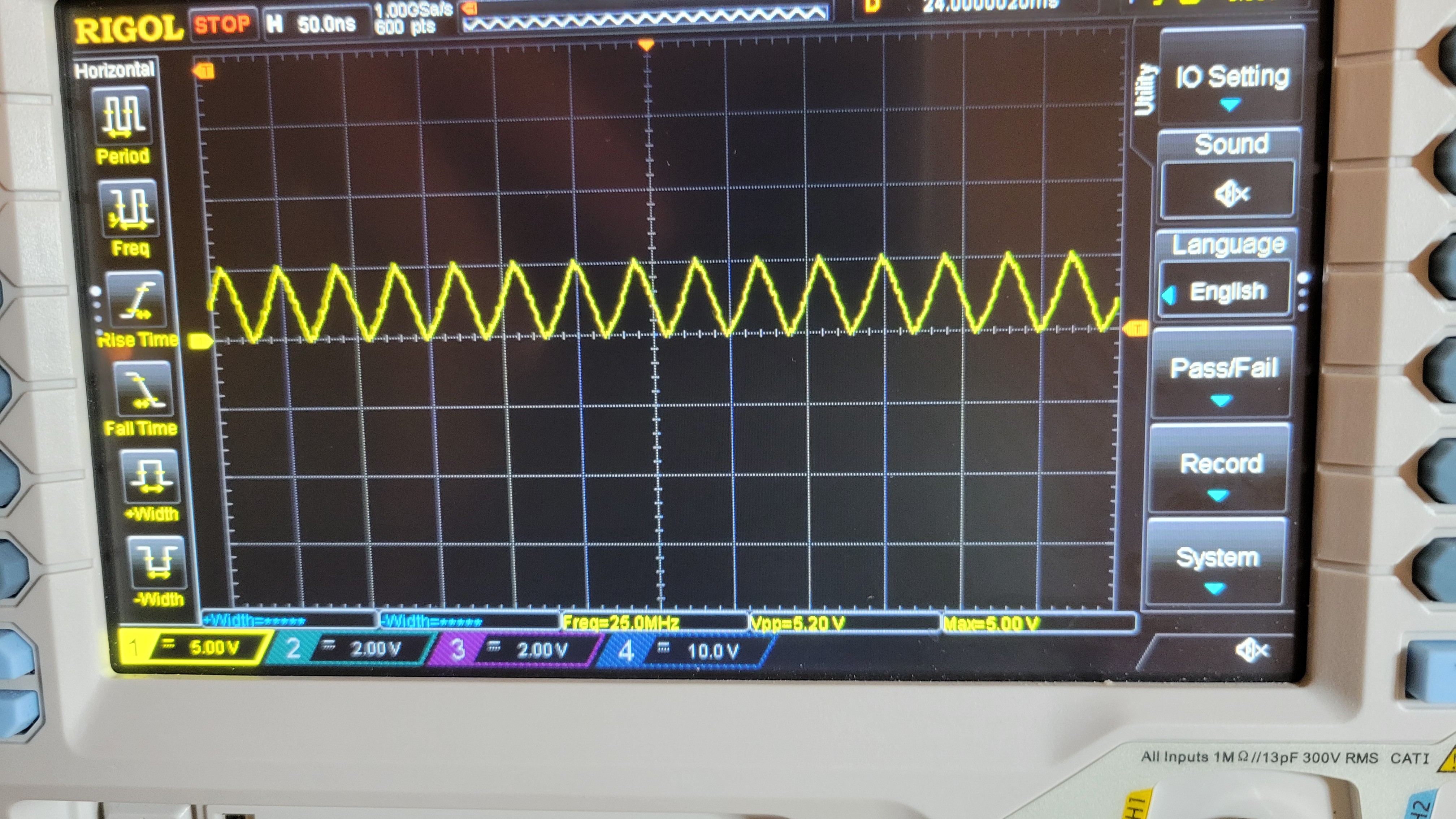
With stable 5v 25MHz signal. Usually clocks are very sensitive to many factors so I was happy to see it's working without to much hassle.
Added AD9833
The signal on the other hand looks with some jitter more over the frequency is wrong(should be 32KHz), at least we got signal 😕
After short debug it was just a software bug where pin numbers were swapped. Phew... Now the fixed version is much better both stable and nice signal (and correct frequency)
Now I started populating the resistors and it looks like I totally forgot the circuit although it was the last one. So here is the schematic with resistor values.

Time to solder!!!
Once I've connected both power supply and usb, things got out of hand.
So now I connect usb only when the main power supply is disconnected and via versa.
Another problem was 7805 d im my case giving only 0.1A I thought it is 1.5A. The reason for the confusion, in my case, is that SMD was 78l05 and didn't give enough attention.
OK, designing a new power supply board
Meanwhile, I got unforseen problems with setting up my board for some reason there is no communication between AD9833 and Arduino. Another problem is that output of op-amp is heavily overdriven.
The first problem can be solved by connecting +5v of Arduino to +5v of power supply. I am not happy from this approach but it's working for now. (The strange thing is that Arduino communication provides 5v which makes both 25MHz clock and AD9833 run, with wrong parameters/frequency).
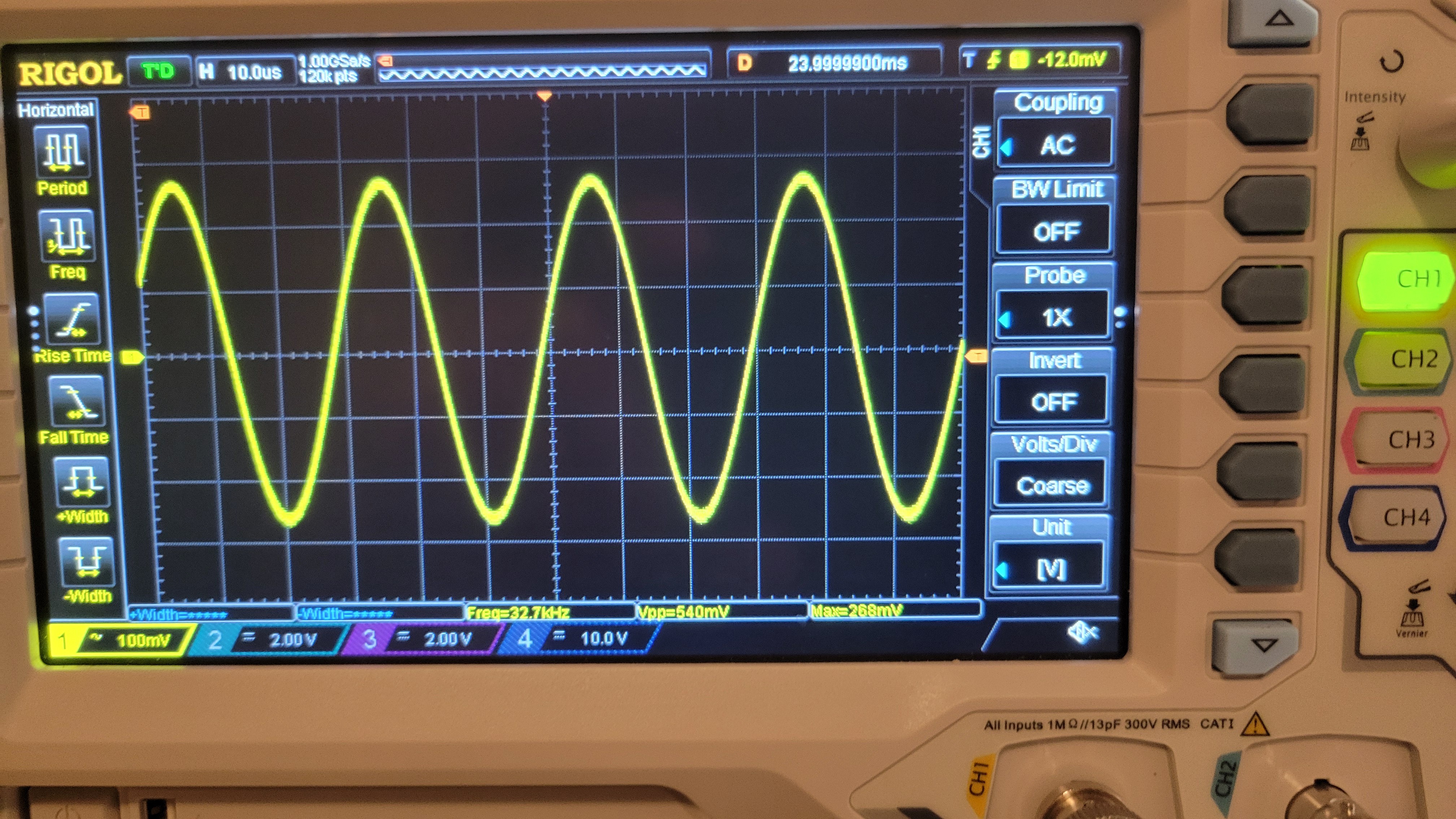
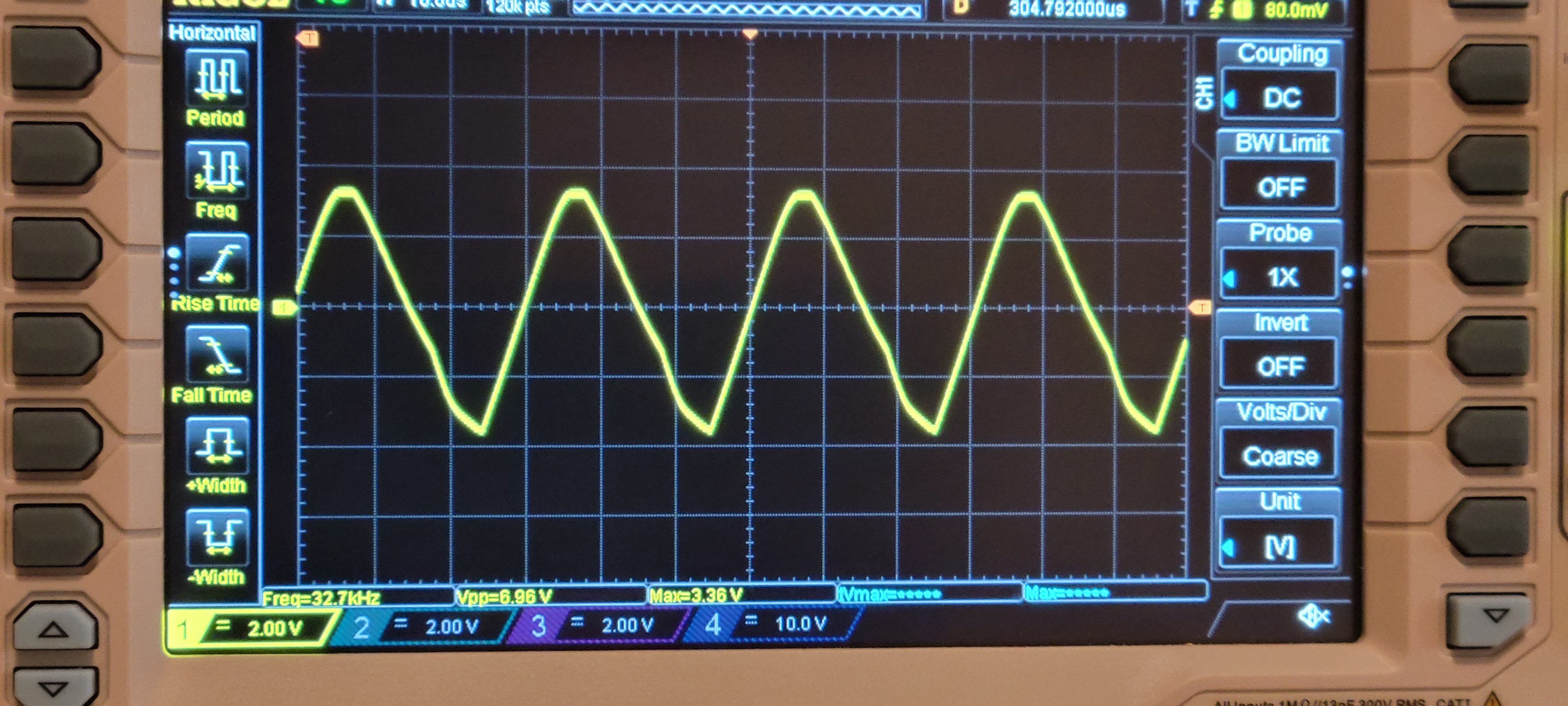
Second problem should be solved by changing resistance values of op-amp. Otherwise it looks like:
Although it's 32.7KHz it very shaky. I don't know why I choose those values (2KOhm and 100KOhm). Probably some copy mistake. I will try 7.5KOhm and 100KOhm.
Now it looks much better, with the right frequency and much more stable

This is great but I still have a problem to connect Arduino to the board I've added 100Ohm resistors This partialy solved the problem. Now it reads only on beginning 🙀
It's ironic that the only 'easy' part in the system gives me the headache. No matter what Arduino UNO doesn't want to communicate with AD9833, only in the beginning. So strange...
It was totally ok with Arduino Nano and AD9833 with factory built board. Let's go back and see what is working with what.
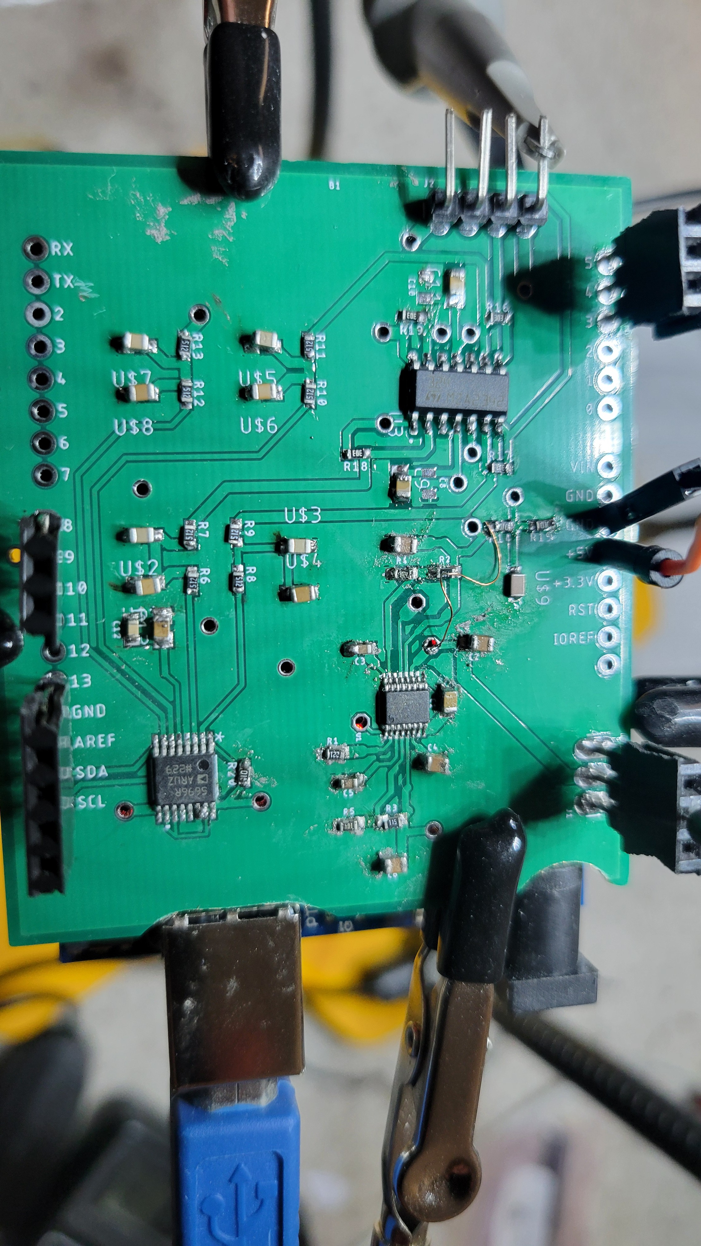
After checking with factory made AD9833 PCB. Arduino is working as expected so it's not Arduino nor power supply issue. After going through schematic I found that one of the terminals, CAP/2.5 should connected to ground instead of Vcc. This solved the issue and now I can control AD9833
And the output of op-amp is nice and stable 7v (almost) sine wave.
Now, added comparator just to find that I forgot pull up resistors. Another last minute change.
Now seems working...
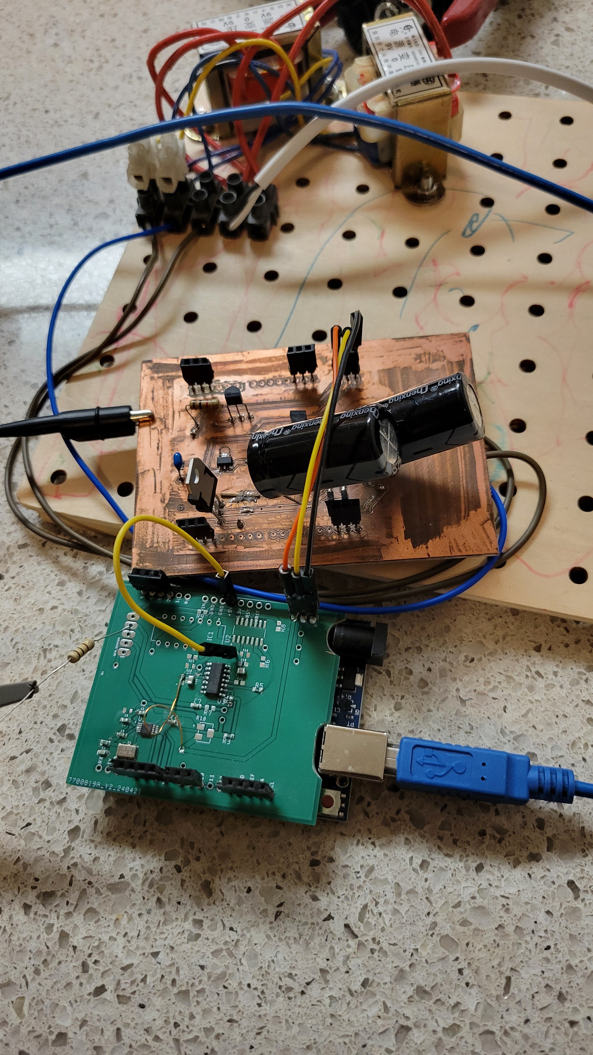
In the end all the board got stacked and looks like
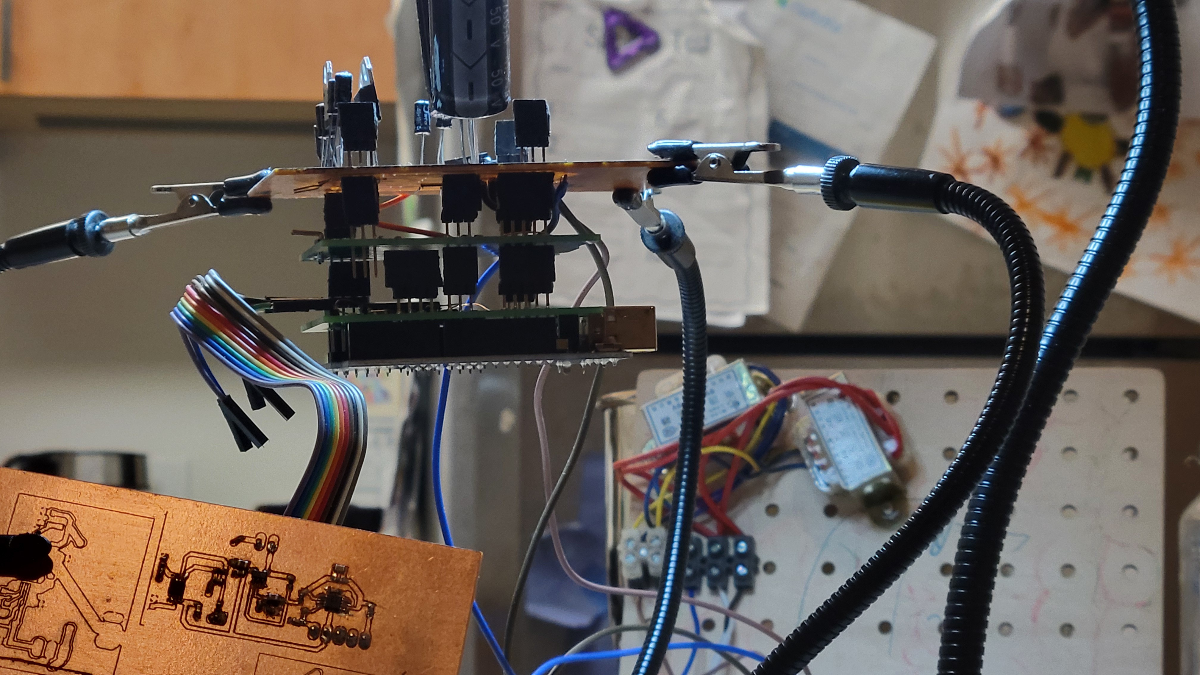
Next step is to connect everything together and make first experiment.
Discussions
Become a Hackaday.io Member
Create an account to leave a comment. Already have an account? Log In.