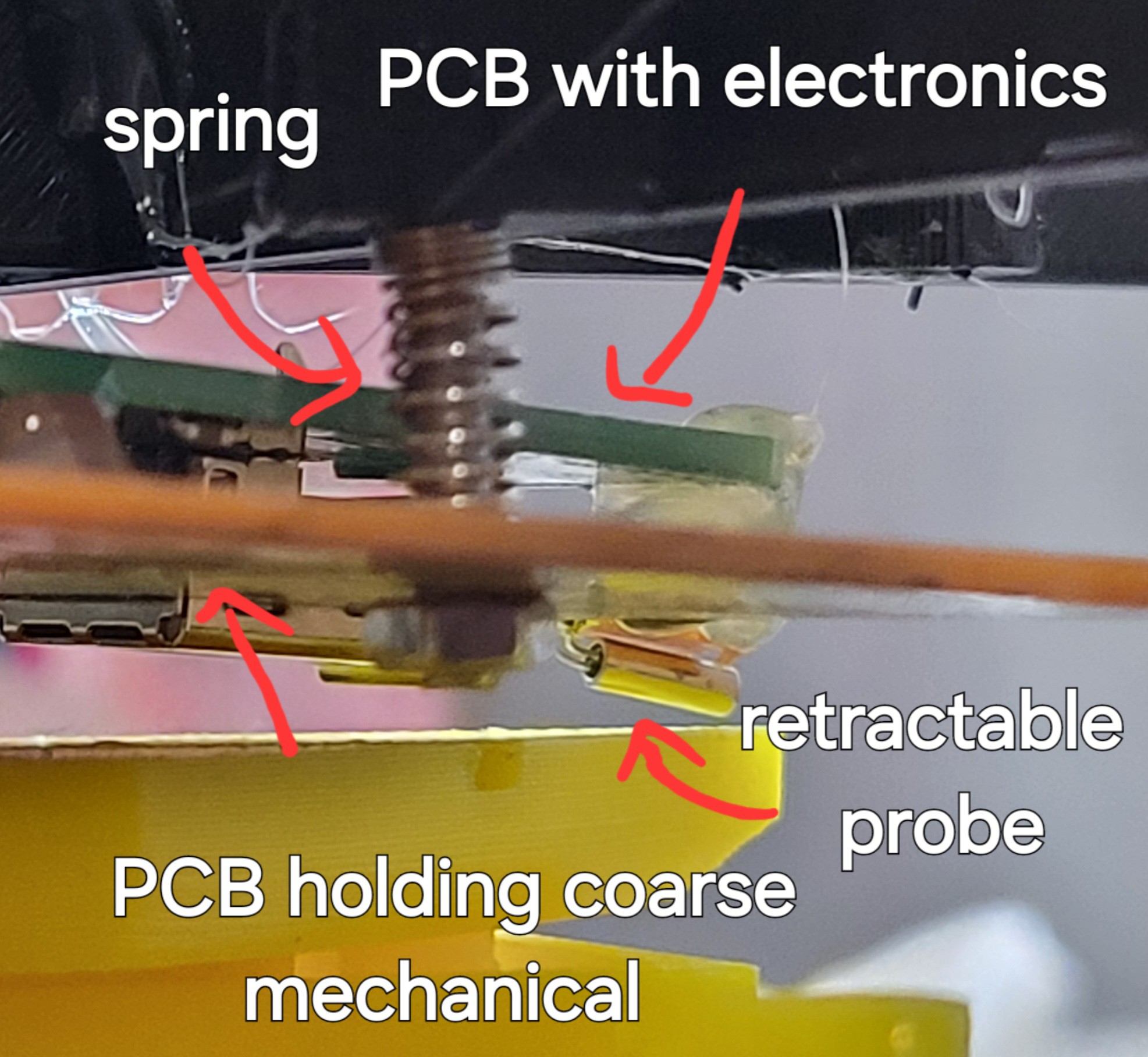
I've added new electronics and better mechanics. Now it's easier to position probe as I like and I can easily change probes (no soldering needed).
Probe #1
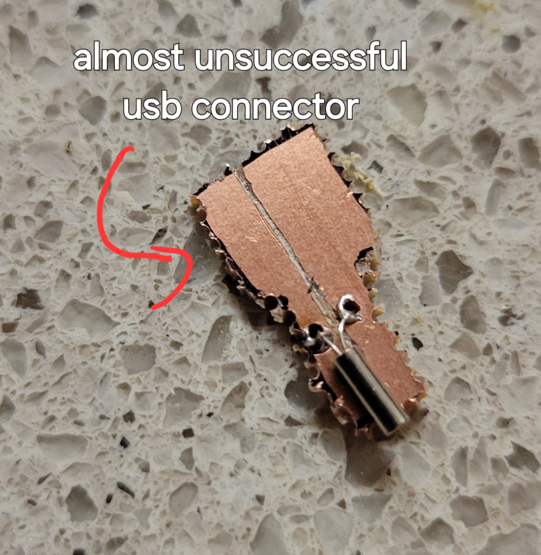
I got it non simetrical for some reason (mainly because it's hand made and not CNC). but it's WORKING! You probably ask yourself why it's important, well because I was afraid that longer lines will add resistance and stray capacitance which will kill oscillation (like in clocks) but it didn't. It works fine! Now it's time for more compex probes.
Probe #2 - quartz fork without the case
I know we already tested it, but I prefer to go slowly but surely.
We can see that it's stable without the quartz fork encapsulation.
Sanity check done ✅
Let's start more compex probe designs.
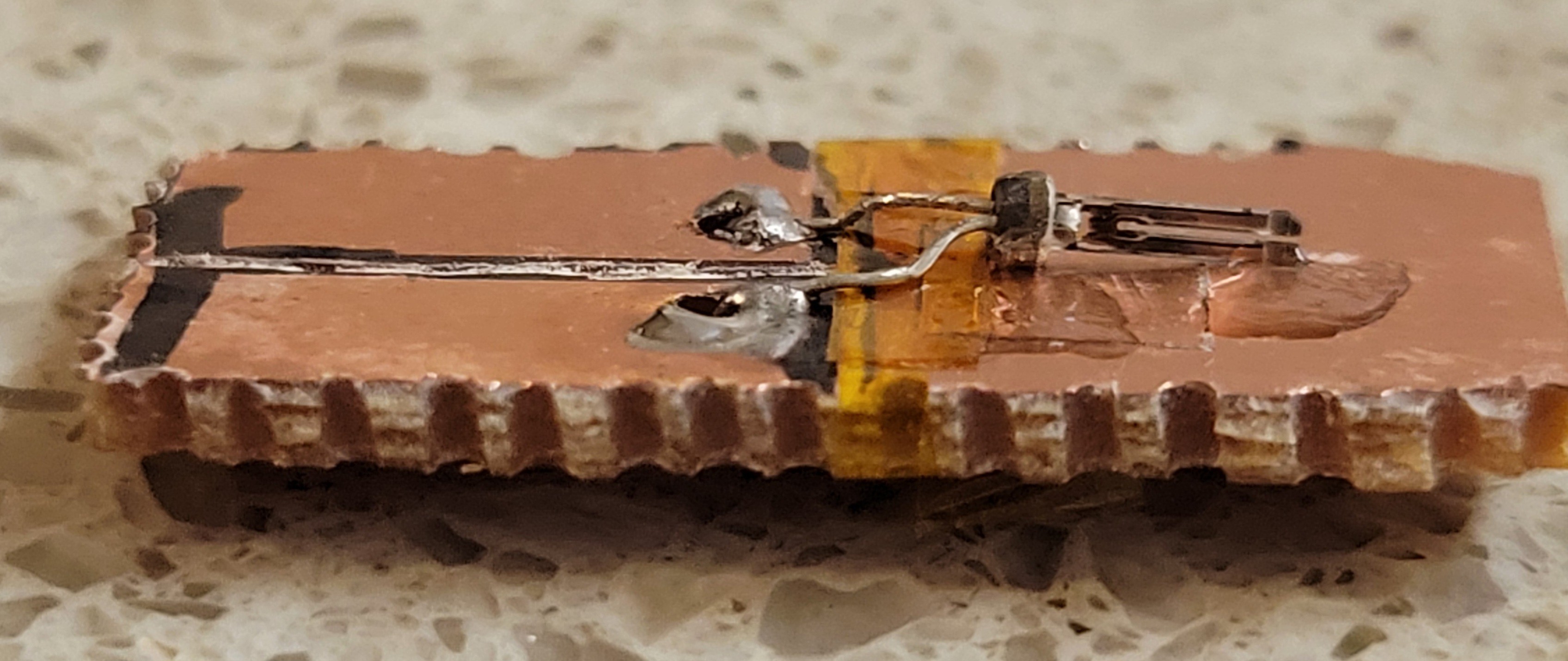
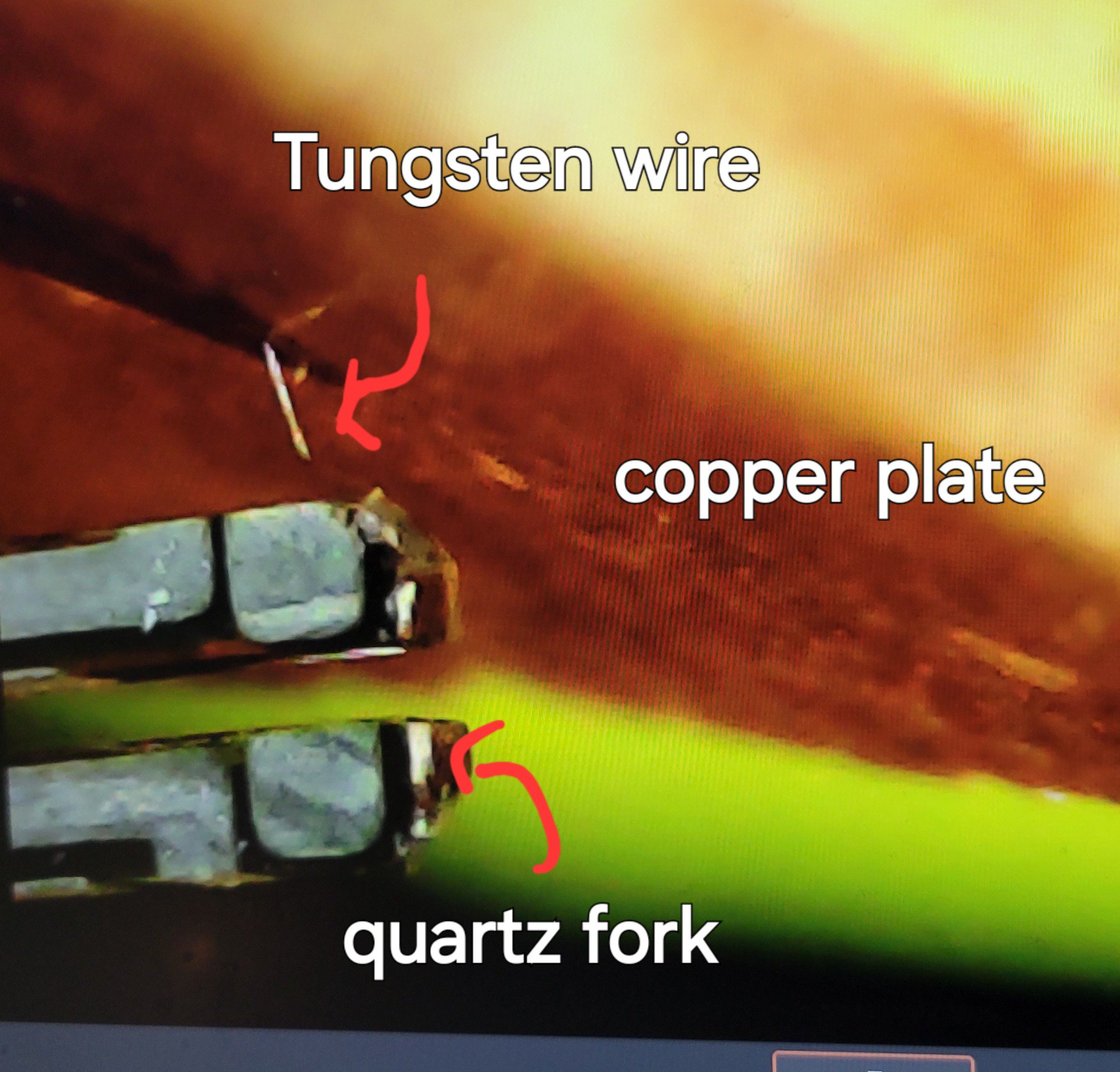
Probe #3 - Quartz fork with Tungsteen wire (sharpened by NaOH)
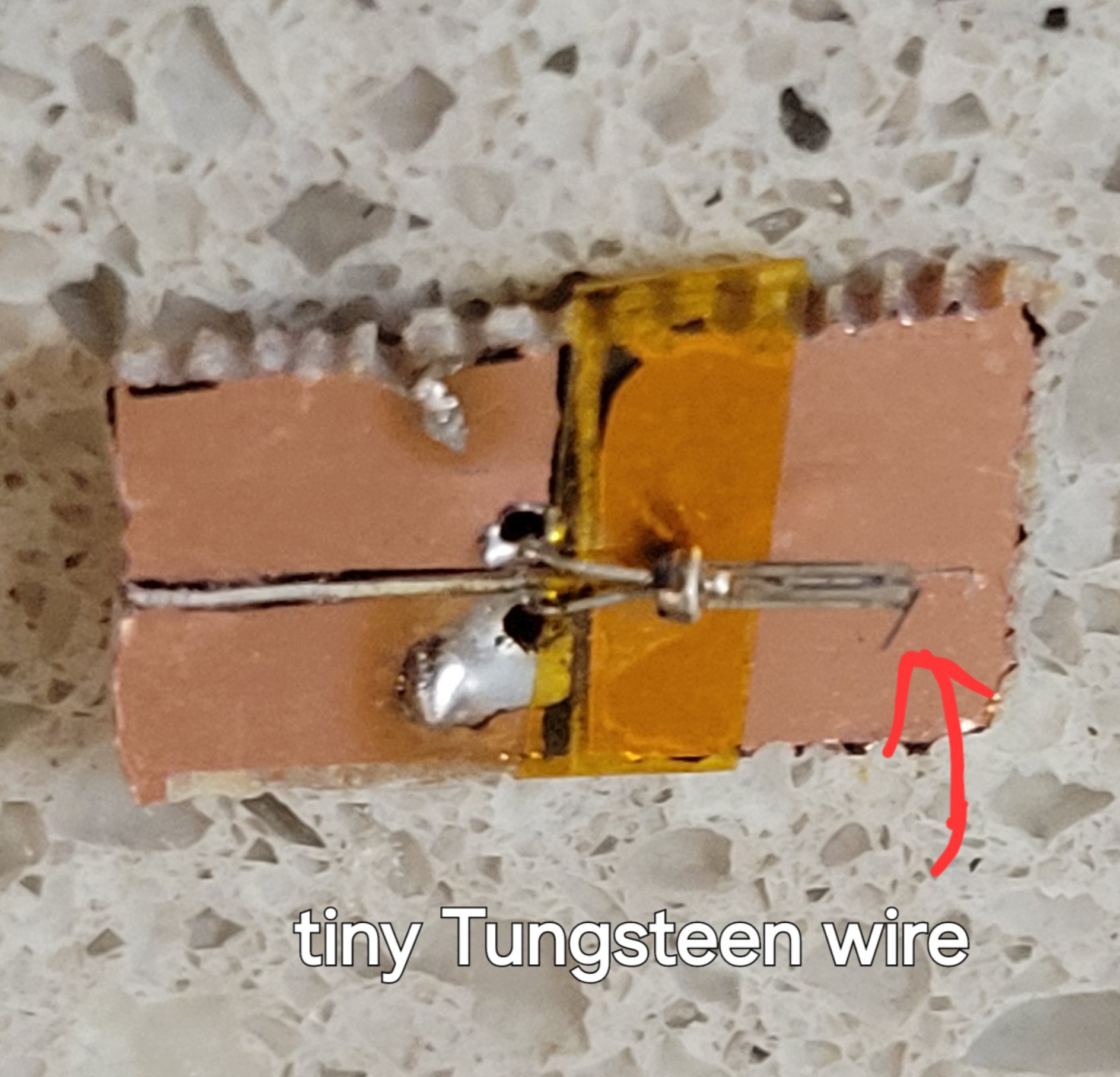
If already wrote about how to create supper sharp Tungsteen wires (this project logo :) ) but once I glue it problem begins. If there is too much glue on the fork's prong it kill oscilation. If too little it doesn't hold the Tunsgesteen wire properly. Glue plus wire kills oscilation sometimes only the glus's weight kill oscilation. like in thie case
Probe #4 - One of the prongs connected to the base.
Couldn't find the frequency. Well I've found it but it was too high I am not sure if it's the main or side lobes.
Probe #5 - I was totally clueless of how to continue.
Then I recalled that I own really thin Tungsten wire, of 0.012mm wide. It's so thin it breaks easily in your hands. But now I got more experience and nothing to lose. I managed to push some wire into syringe. Since it was so tiny I thought to use 0.1mm wire to paste the glue (instead of toothpick).
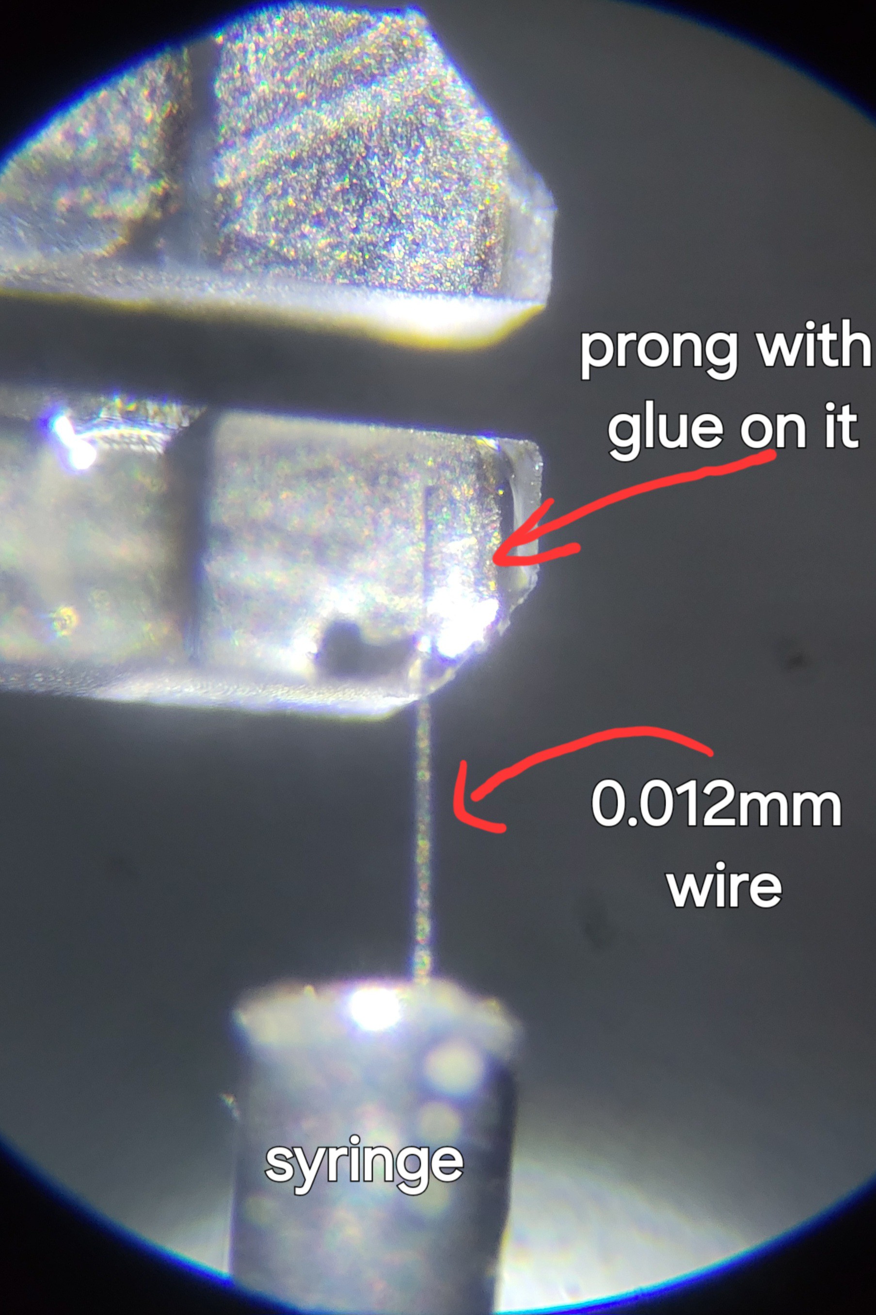
The glue was strong enough but I had another problem. Since the wire was so short I couldn't etch it. Luckily (yeah, I feel lucky today) I managed to cut it with scissors. (It's impossible to do that with 0.1mm wire, it breaks the glue)
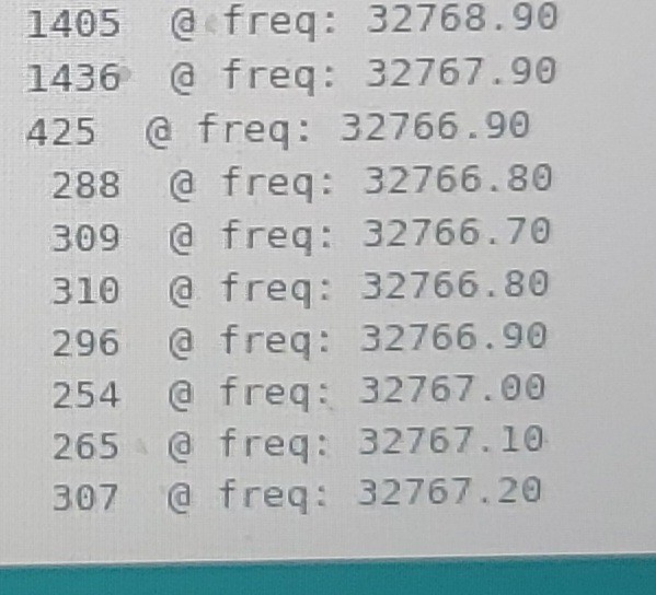
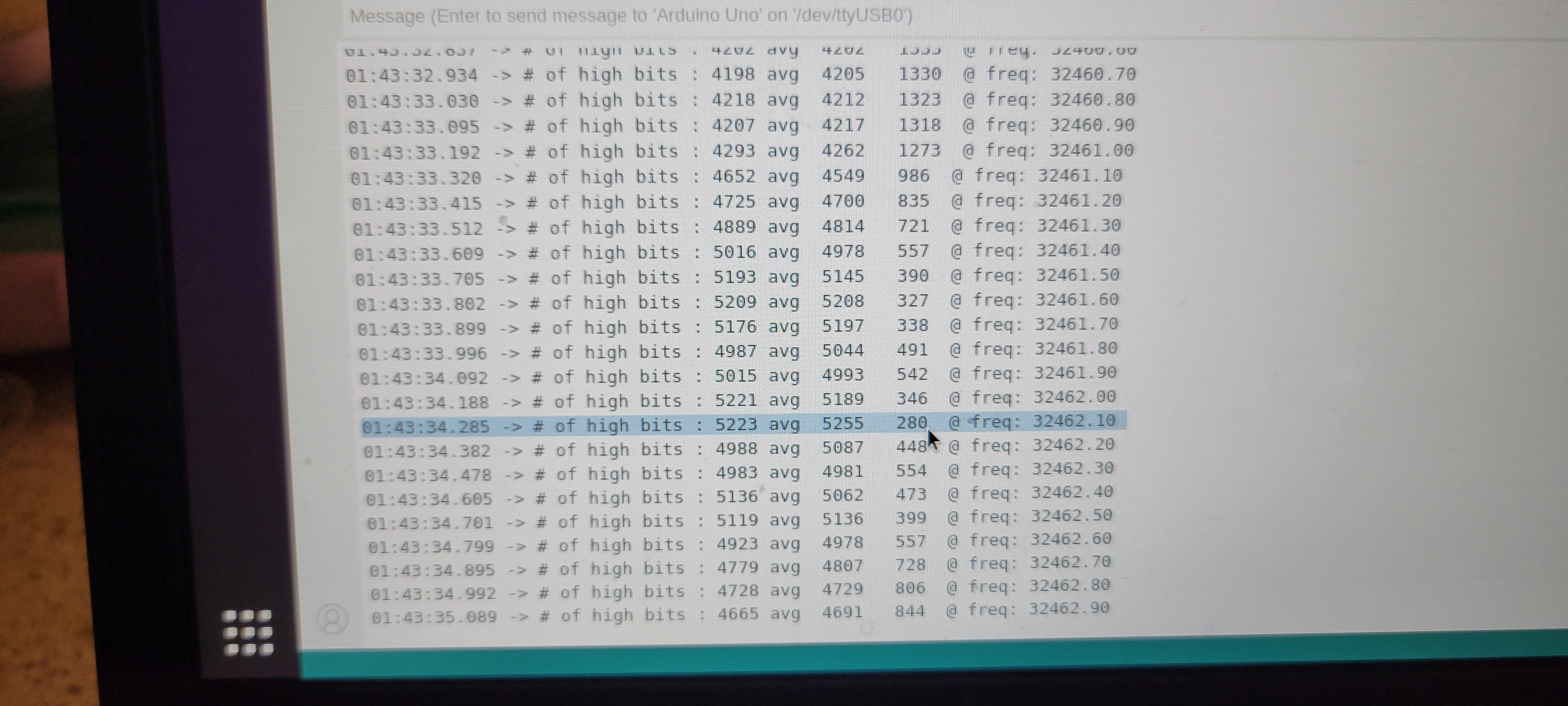
Now I've tried to scan the frequency and TA-DA! I got stable frequency
Now it's time to lower the probe and see if it successful and we got AFM or all this project goes to garbage.
Stay tuned 😉
P.S.
I found fundamental design flaw in my design. I've noticed that sometimes the difference I got is near zero and sometimes near maximum of 5k.
The reason is that quartz fork is oscillator with its frequency and phase.
That's why sometimes I get no signal, it depends on the phase between input and output of quartz fork. There are many ways to solve it but for now I will just restart the system and hope for the best.
After some rethinking, it looks like we have software solutions. AD9833 is able to change it's frequency programmatically. So we can start normally look for high and low. If not successful, change phase by 90° and try again. Once right frequency found try to get better results changing phase, until looked.
Update:
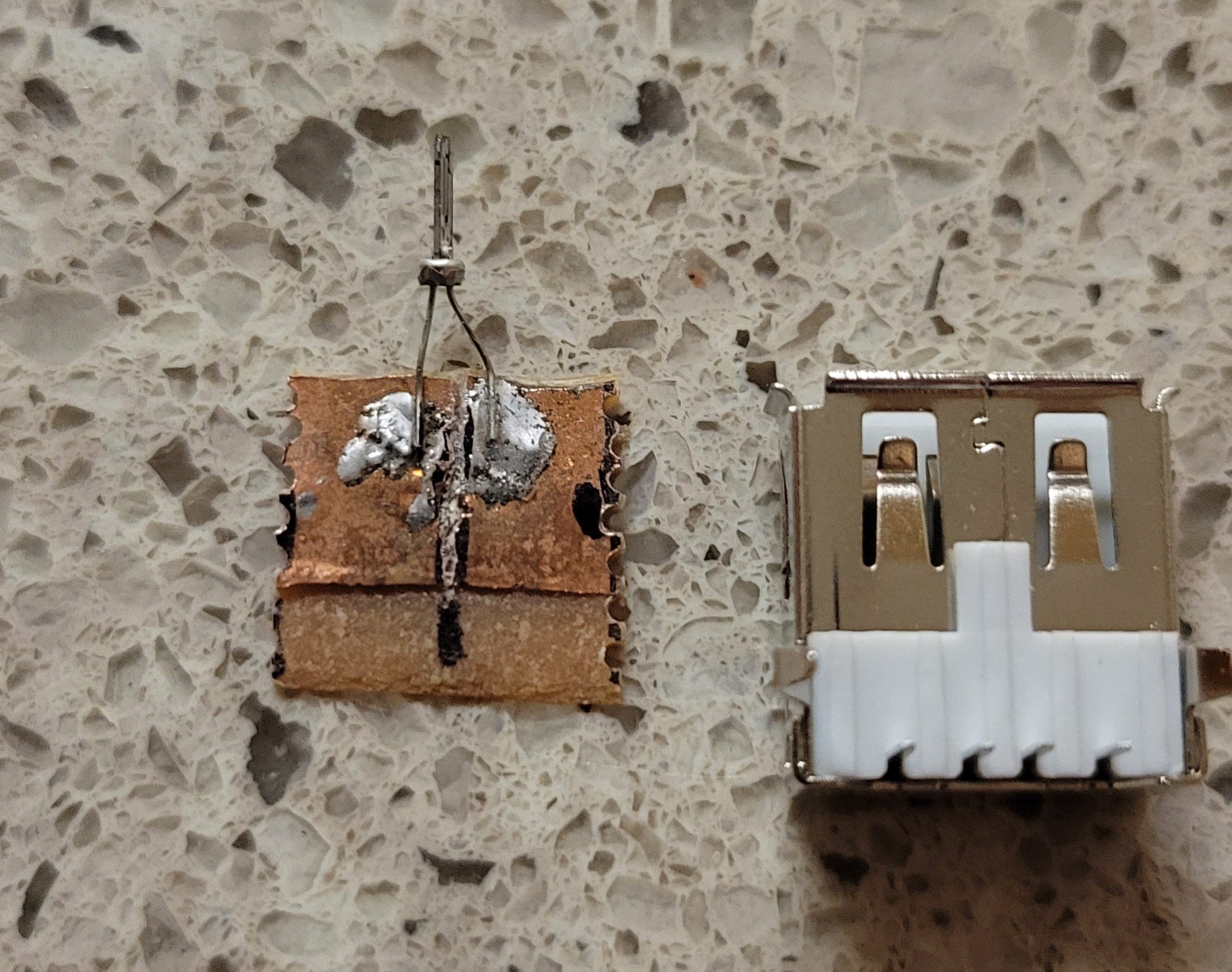
Started another test, failed as the usb metallic cover was on the way. Few power moves the pliers and it ok.
Now we had some issues with frequency. I didn't had mechanisms to set frequency. Now I do. Continuing to the test of soft landing this time with real (not yet sharp) Tungsten probe.
Update II:
Was able to do first measurement with Tungsten wire.
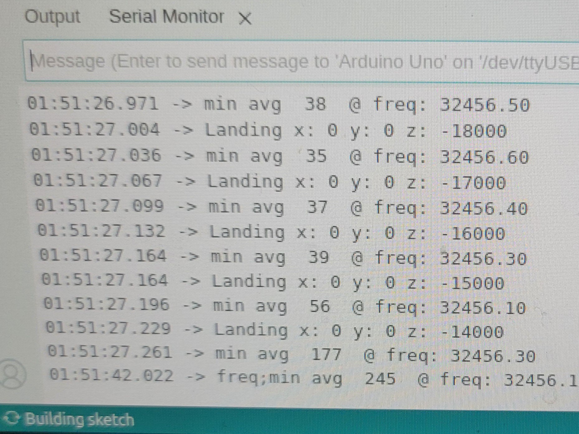
The procedure is run 'range' which runs coarse frequency change of 1Hz and range of 200. This finds the frequency where maximal/minimal eclipse occurs.
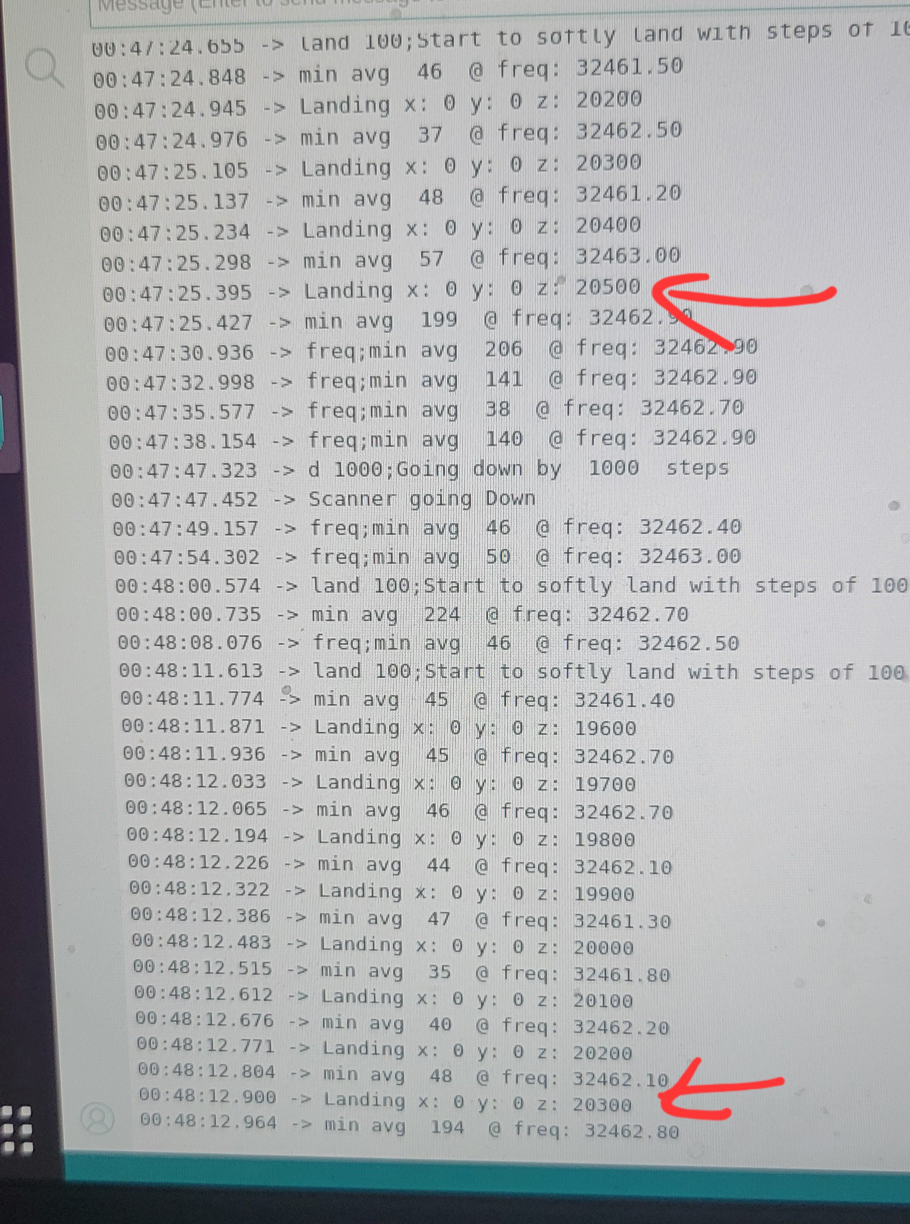
Now we set new base frequency by 'bf' and run 'land' function steps of 100 (I ran with 1000 and crashed into sample). If fails to land change high of micro meter movement (open flexture Delta stage).
Update III:
Added 'ph'ase function which changes current phase. It helped to change convolution result from ~120 to nice ~ 30. No matter what I did I couldn't go below 30.
Going step by step, I thought it would be a good idea to test the 'land'-ing function is consistent. I tried to descent in big and small steps but the result is same if you find a place where convolution changes and goes up and down again the convolution still high. This is the basic step for measuring height. If this not stable we cannot go to scan. Now when I think of it one of the problem could be phase change once probe touches sample's surface.
Update IV:
Today I was able to depth difference between two consecutive runs of 200.
It was without shielding and without vibration reduction. The only difference was that now all my appliances are off, and windows shut, as it cold and super late.(I am happy I don't have to rebuild the electronics)
Let's wrap everything in aluminum foil and go to the next step...
Update V:
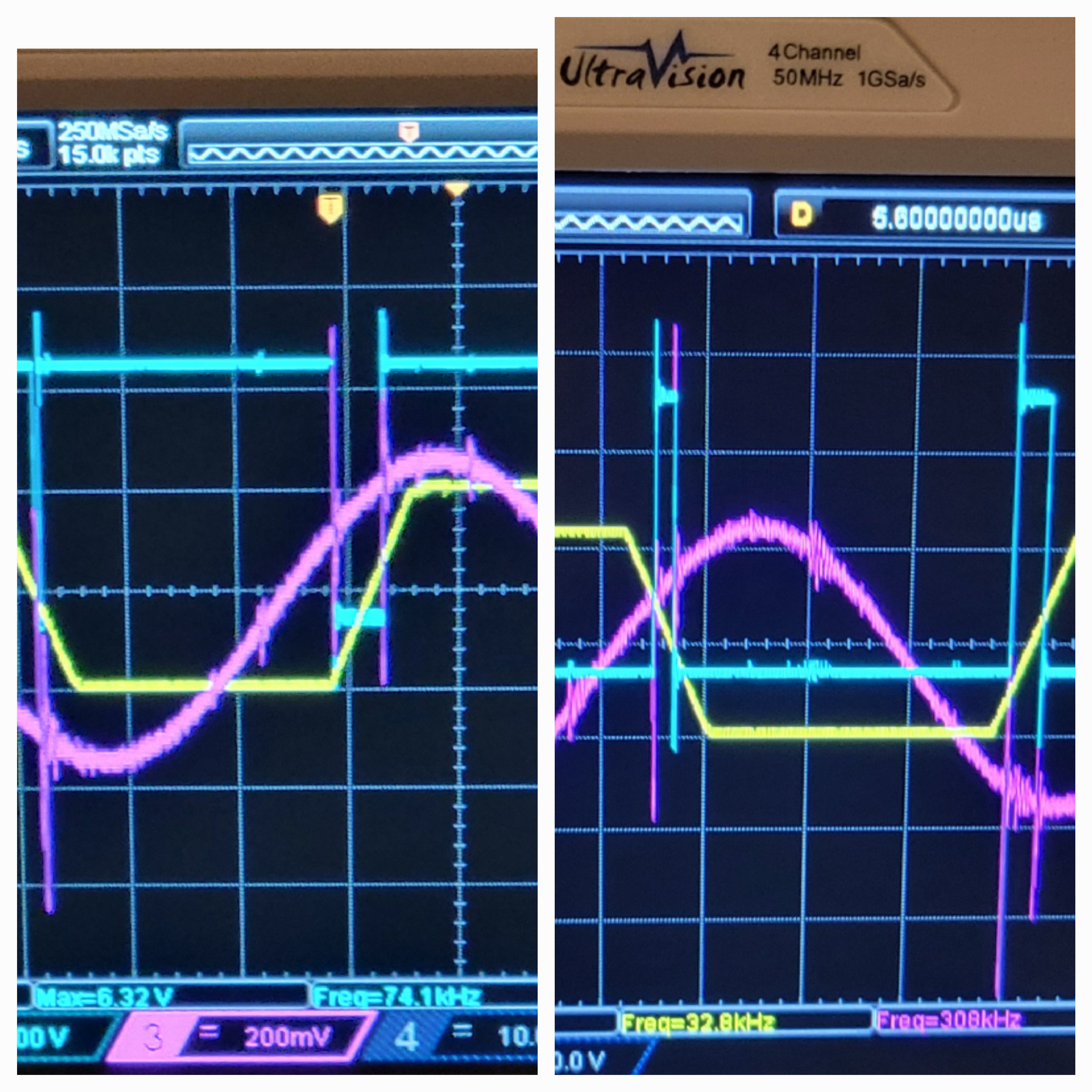
I discovered some disturbing problem. There is ~120Hz stray signal on piezoelectric output of about 75mV.
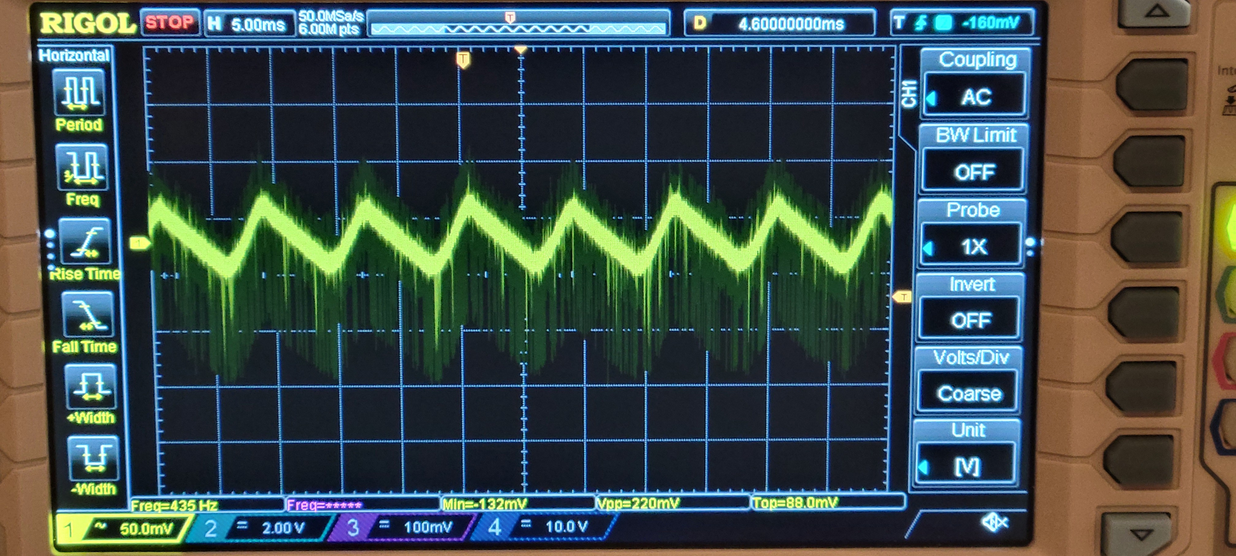
I've traced it back to power supply. The LM7812 was giving those triangle signals. Long story short. My transformers gave me 15VDC. Luckily I got step up transformers. Once I got 30V, after rectifier bridge. I got white noise signal as expected. [Feeling lucky today]
Update VI:
[Not feeling lucky today 😕] It turned out that I burned all my boards, simultaneously. Yeap, I am that talented...
Let see... One of power board components short circuit 15v to 5v rail. The result is 8v on 5v rail, ouch... All sensitive components just went boiling...
On piezoelectric board at least DAC died maybe others too.
On input board at least AD9833 signal generator died, maybe others.
QFM module board is not responding neither.
Although it's super depressing, especially when I was inch from finishing the project.
I staying positive, like Monty Python used to say "Look on the bright side of life".
But don't worry I have really great idea how to elegantly overcome this, kind of 'Make lemonade out of lemons' ver.2.
Stay tuned...
Next step would be a real scan. (And if successful run scan with etched probe, this will the end of this project)
Discussions
Become a Hackaday.io Member
Create an account to leave a comment. Already have an account? Log In.