TL;DR -
Now you can buy all electroincs of this project (boards with components assembled) just by two clicks on PCBWay. No prior knowledge of electronics required. Plus, you can buy all the bodyworks using 3D-printing services. All is left is some gluing and some minimal soldering that everyone can do.
The longer version -
The idea is that this project will be accessible to all, not only electronics hobbiest. One of the problem with is that this project has lots of electronics. I was wondering, how someone without soldering skills (no, it's not easy as it looks like) and good electronic knowledge could make this project?
In perfect timing (burned most of components by applying wrong voltage) I've been contatcted by a guy from PCBWay who was willing to support the project for a honest review. [Oh well, now I'm biased 😜]
It turns out that PCBWay and other comapnies are providing something that called PCBA. Which stands for PCB Assembly. Wait! What?! It's fantastic I could provide my schematics/boards and people could get assembled board with all the components.
So, I wasn't laizy and checked other companies all had the same answer put the files here (some demanded to convert to some bizzare formats) and engineer will return to you. Big NO,NO! I want people to push the button and get those boards.
I've used OSH Park, they have realy nice sharing option and it's supper easy to buy boards from them but they only provide PCBs.
For example, JLCPCB provide something close to that, you need to provide project files, BOM file and CPL file, then it goes through process of choosing components. In my case it chosen non-standard components and price was dobuled (plus fee of $3 on each non standatd component). After going each component and choosing the basic one price dropped to something reasonable. After that it took me to other window where components were placed for some reason all my ICs were in wrong orientation. So that had to be fixed. The price was the same as PCBWay give or take 10% (but it provides you two assemled boards). I've tried to ask if only one board could be provided but nope. For seasoned hardware developer it could be a good solution but if I want to share it with people who just want to build AFM with minimal electric knowledge it just not an option.
This is the point where I got realy amazed by PCBWay [Maybe I'm bit biased here] they DO have a posiblity of sharing the project, with all components.
To show how things may go easily bad was my experience with OSH Park. I got QFM board shared project in OSH Park, but they provided only the PCB (no assembly) and I failed to solder all the components properly (yeah, took me a week to realize that) and they don't provide the full schematic before you buy. I ended up building my own PCB layout just to make it work.
Biased? Maybe, but until now couldn't find any other service that provided PCB and component assembly which could be easily shared.
We can conclude it with the following: You got mainly three options.
- Mill PCBs and assembly by yourself [fast]
- Buy PCBs and assembly by yourself [cheap]
- Use PCBA services (such as PCBWay) to do it for you. [easy]
Now, lets look at the solution in terms of time and money.
Milling yourself is the fastest (and cheapest) but you have to own CNC machine and the knowledge to make PCBs. (It can be quite tricky). So timewise it will take you few minutes to build PCB board and few hours to assembly if you have good soldering station (plus good hands) and knowledge to solder 0.5mm pitch (distance between each leg of the integrated circuit) components.
Buying PCBs can save you the hussle of building ones but it takes about 2-3 weeks to get to you (unless you pay much more for expedit shipment, then it will take only 7-10 days). You still need a good soldering station (I use hot air gun and tiny tip iron) with magnifier glass (and other gadgets once things go south).
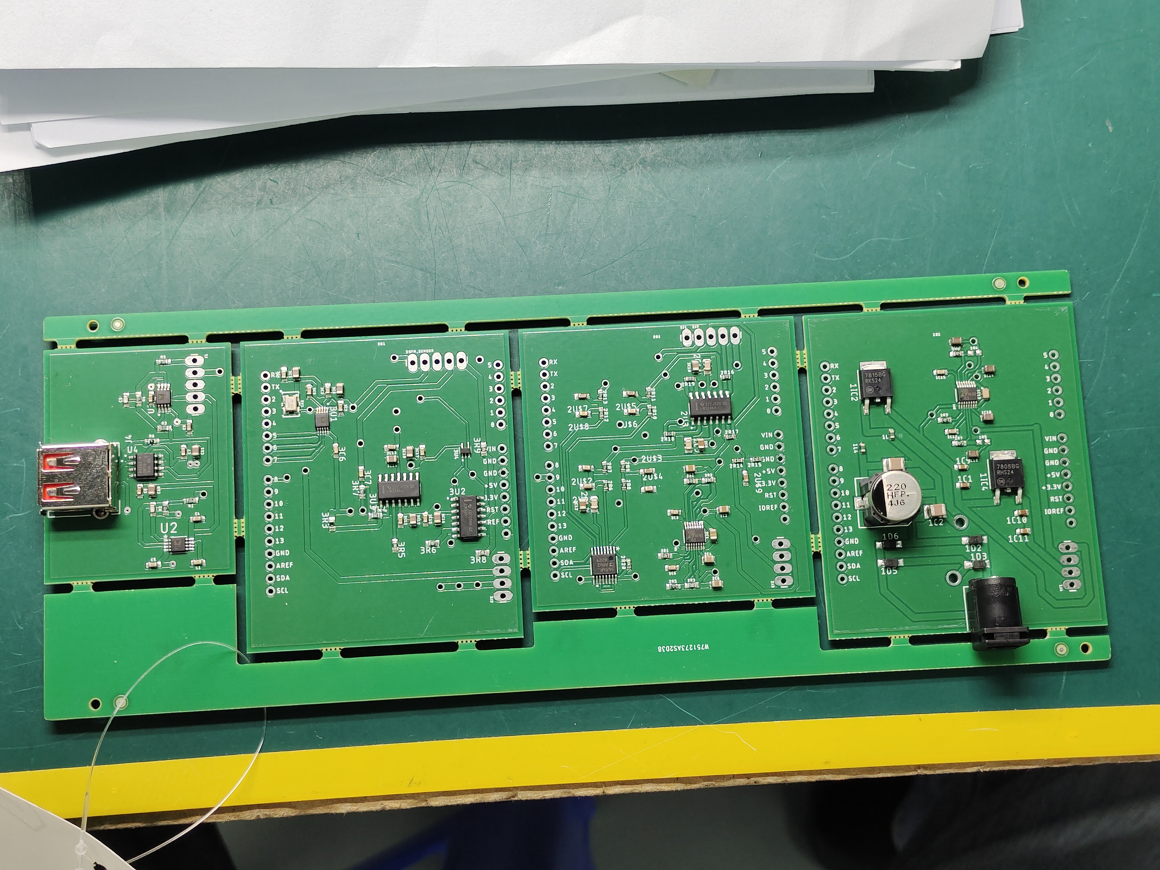
PCBA is great solution which will gurantee that all electronics going to work out-of-the-box but it takes month to get and it cost you much more. In my case I managed to squeeze all my boards into one 'panel board' so the assembly was $30 for all four boards (all electronics in this project). Plus, components which are about the same price I got in Mouser. The funny thing is that they charge you $30 for 'panel PCB' assembly which in my opinion is nothing compared to time you invest doing it manually. Finally it cost only $220. Unless you want practice soldering I strongly advise to use their service.
I guess there is no silver bullet, every one should choose what best for him/her.
Update:
Got the boards and started testing. Power board was missing two resistors (I don't know how I didn't notice it), but it was easily fixed. Sensor board got problem with xor, but it's my fault as I used new component without testing it first. Piezoelectric board got messed up resistors in the dcdc charge pump, so values was not a full range but I could change voltage on DAC via software. Good starting point, few tiny fiexs and we are back to point where we were before.
Update 2:
Fixed resistors values, it's my bad. I changed voltage to 5v and back to 12v but forgot to update schematic. It's looks very stable even on resolution of 20mV.
With every 50 steps is about 10mV.
Update 3:
Xor problem is actually mine, I removed pullup resistors thinking it belongs to old XOR. Not a big issue will fix it.
Only problem left is QFM module, something weird there, once I fix it we can continue exploring our microscope...
Update 4:
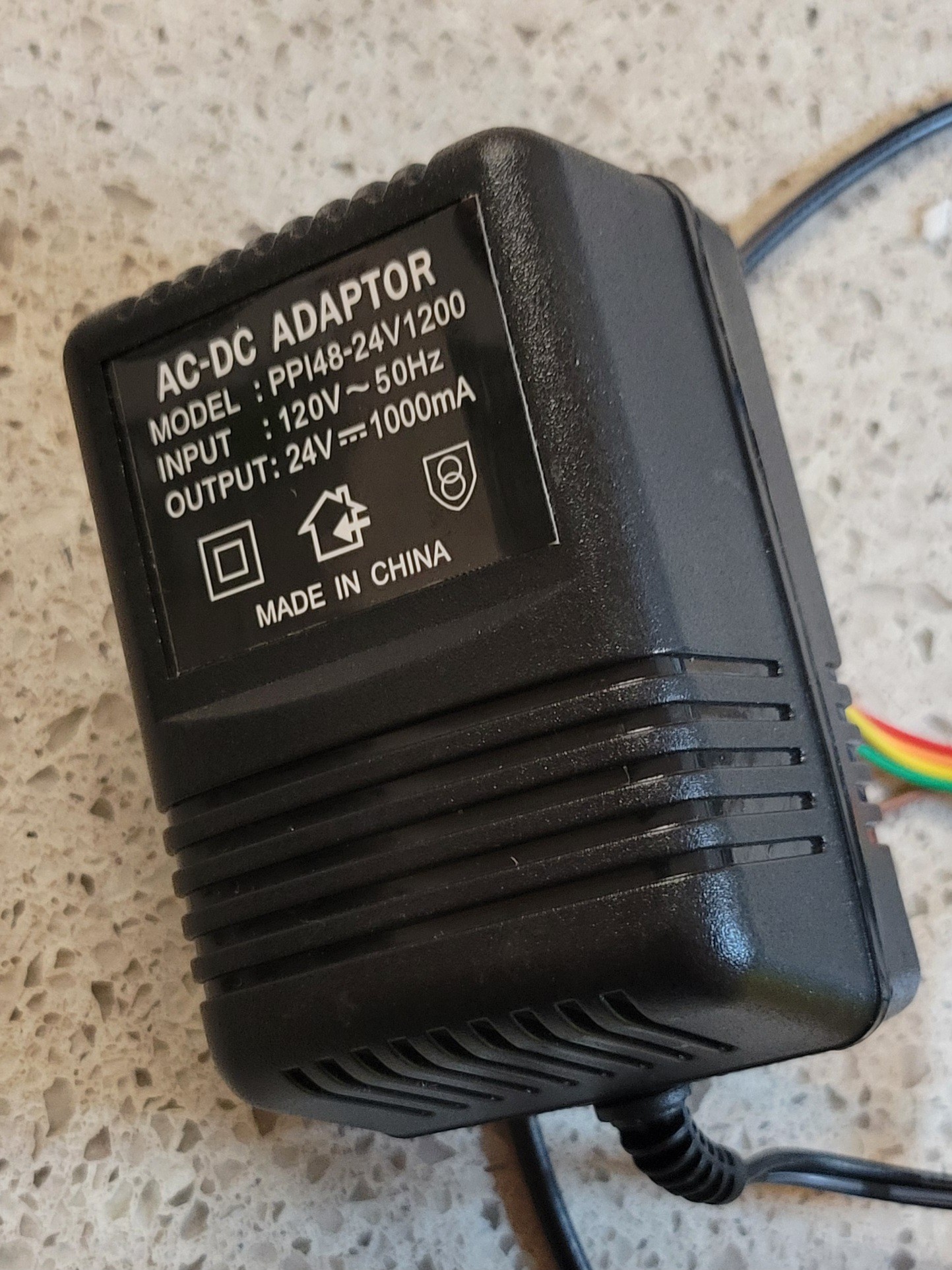
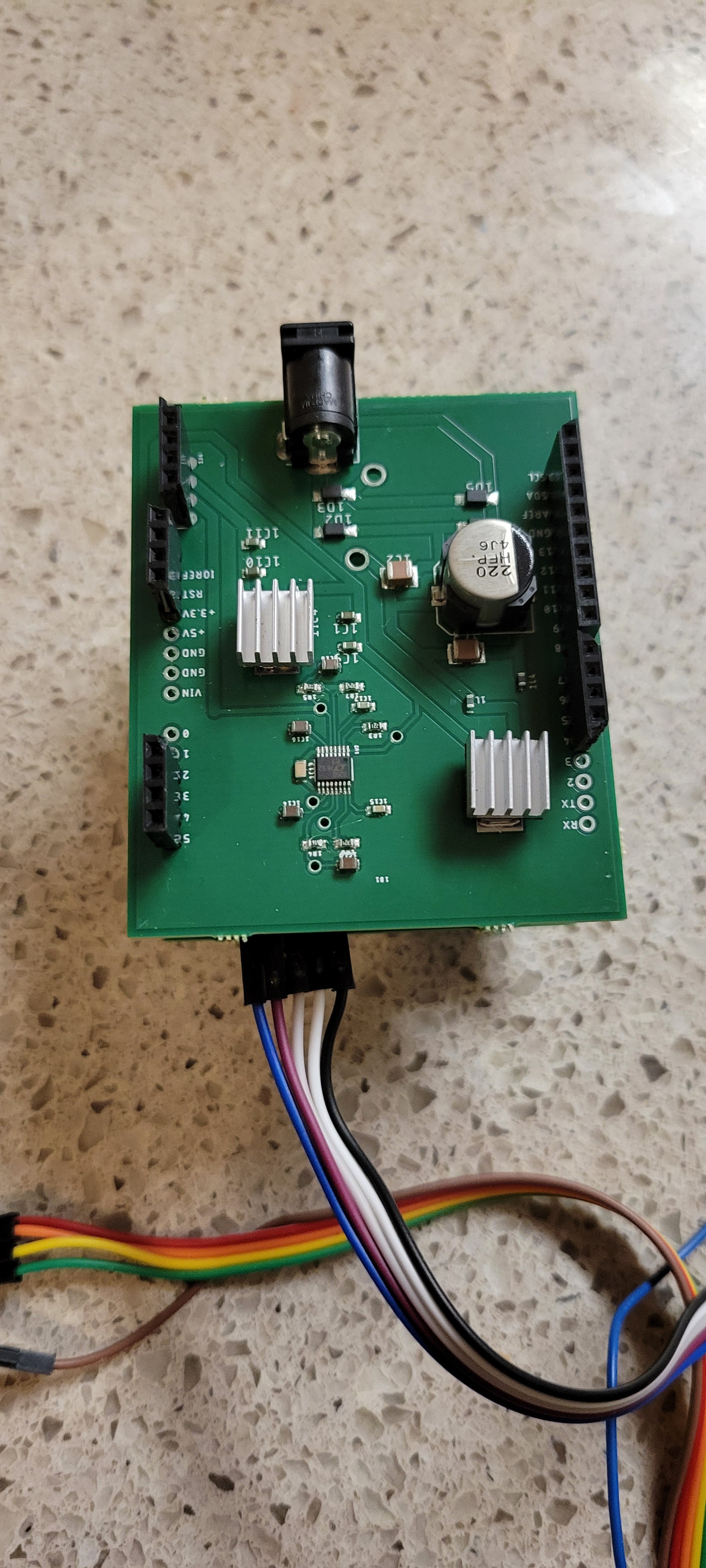
Added non switchimg power source
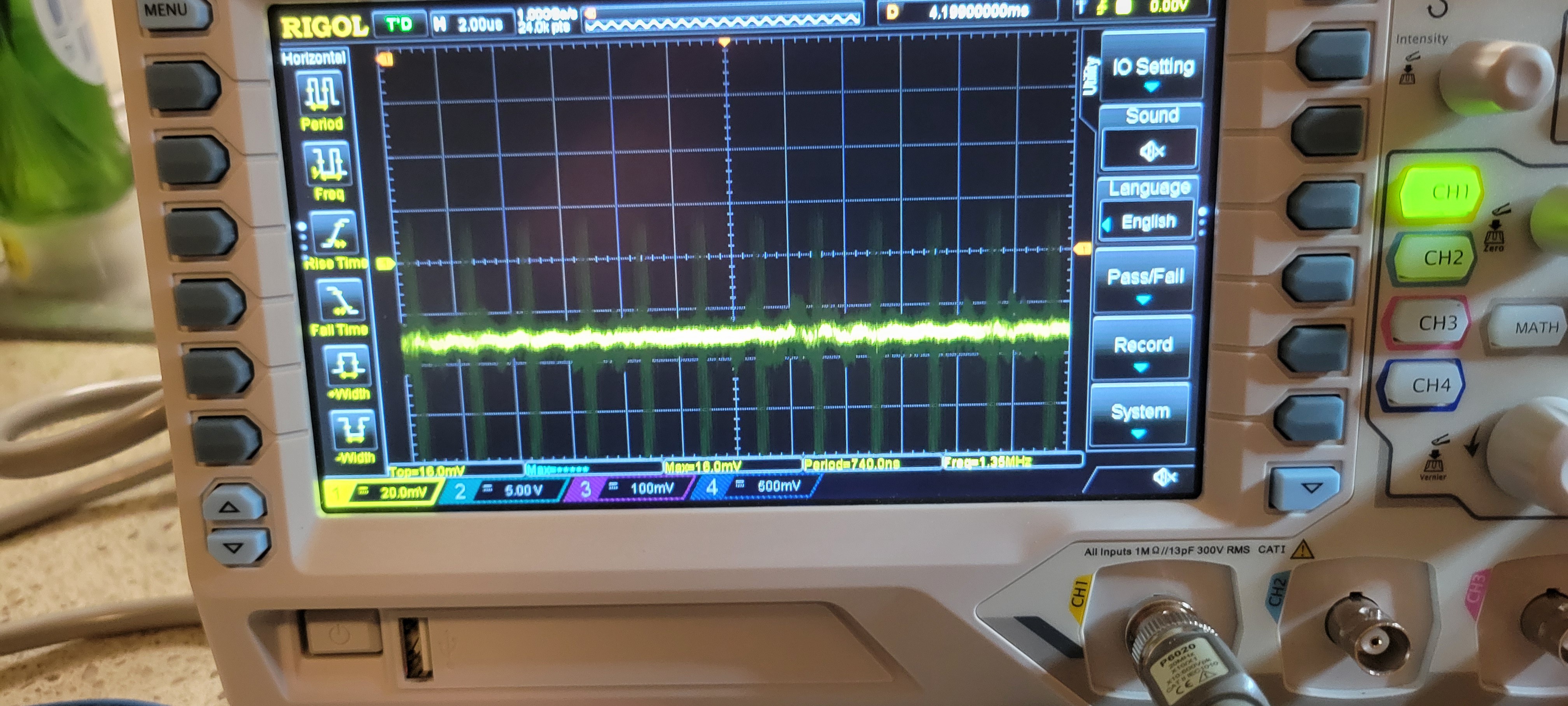
Added two resistors as pullups for lm339 the result is
The output was noisy but it's ok, since I didn't find the correct frequency. Last thing voltage regulator got pretty hot, I guess heat dissipation is needed. We are in really good starting point
Update 5:
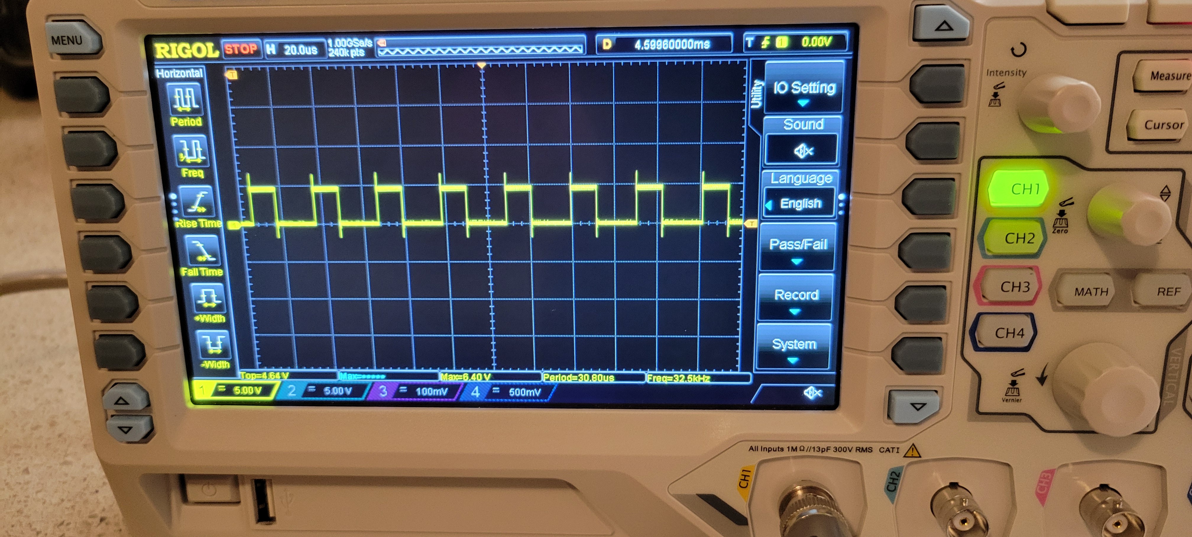
Everything seems to work now. Looks even better than the real one
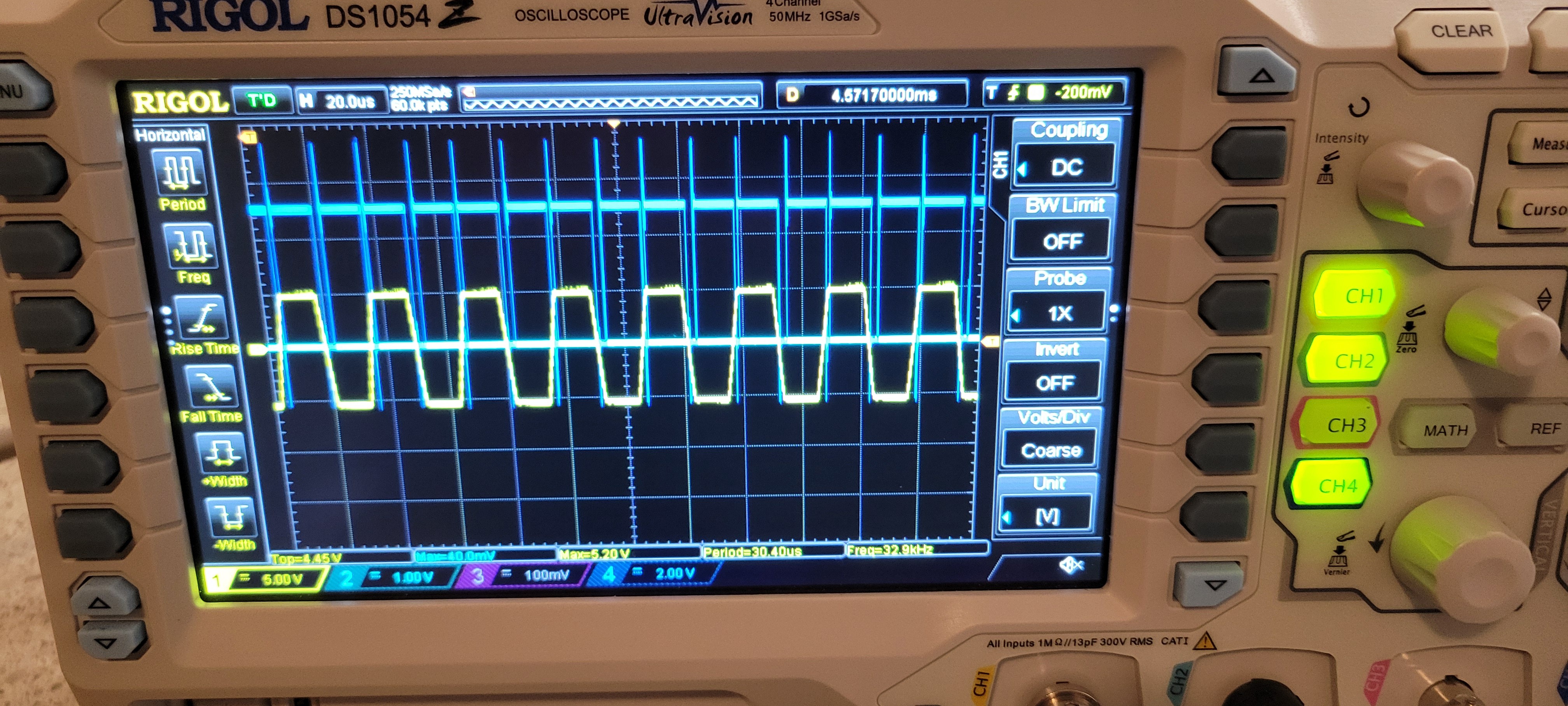
The only problem I've noticed is that it takes time to change frequency. Maybe I should rewrite the code so frequency will constant and only check output (blue line in the picture). This can be done fast.
Update 6:
Added heat sink on voltage regulators.
I found that changing frequency takes 2-3 to stabilize on output of QFM board. Because of that I am changing how software is working. Now I want to find best frequency and stay there until touching something in that case output will be different. By the way, now system looks much more stable
Update 7:
I am working on updating PCBWay project, so all the problems that I found would be fixed in the next version.
Discussions
Become a Hackaday.io Member
Create an account to leave a comment. Already have an account? Log In.