After long, long work and long, long calibration I got my first image of copper plate.

The graph is reversed, since in my setup when we get 250 it means tip didn't touch the surface
Funny thing I found is LibreOffice and Google Sheets doesn't have 3D plots. So I had to find some simple python code to do it.
------------------------------------------------------
Manual calibration is difficult since each touch takes all system out of stable state.
So, I've moved back to OpenFlexture with stepper motor which can be controlled by software.
Luckily we don't need any electrical changes

Looks good:
I've finally figured out how automated calibration should be performed. Move micropositioner up one step go from down to up on nanopositioner if found stop otherwise go down in nanopositioner and make another step in micropositioner. At some point tip should toch the surface.
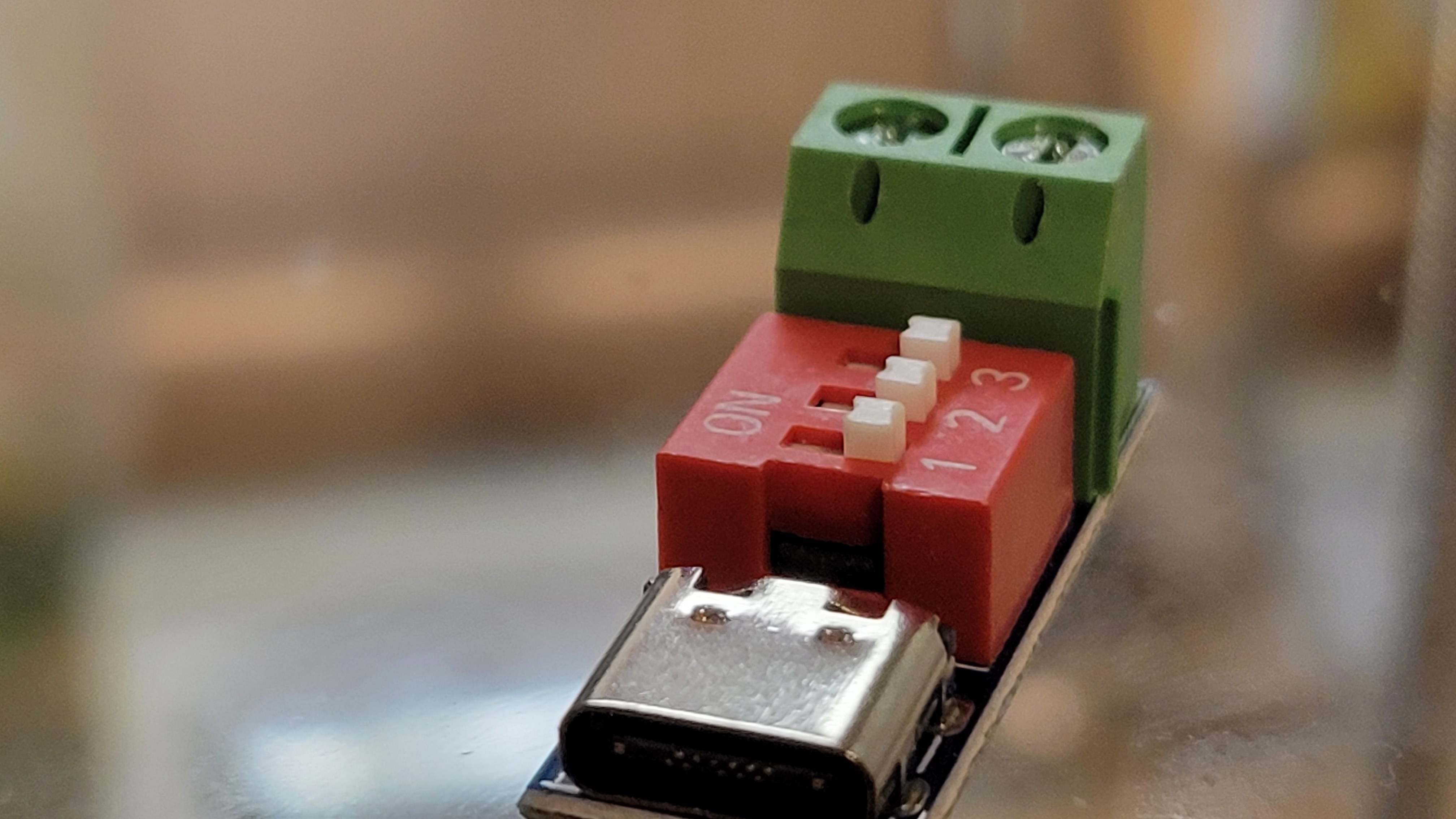
After some thought I've decided to add another power source for power hungry stepper motor. Although it possible to use original power board the voltage regulator became too hot and at this point I didn't want to lose another board. USB-C PD (power delivery) is an easy way to connect USB-C adapter and get its power.
It's small and can get you voltages from 5 to 20v depending on what your adapter provides.
----------------------------------------------------------------
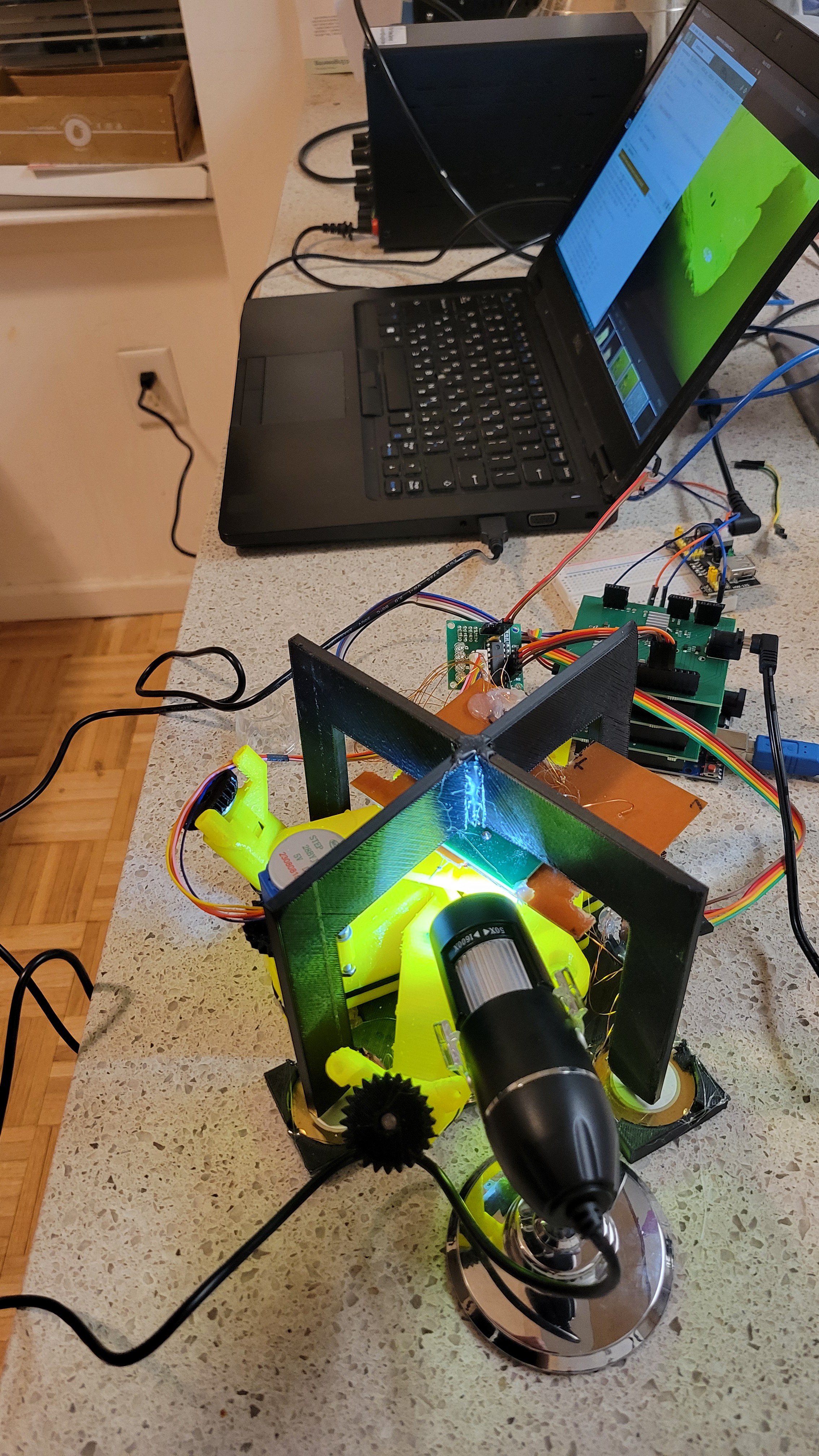
I've tested the stepper motor with microscope and saw that on micro meter level it moves much smoother than when I touch it with my fingers.
----------------------------------------------------------------
I was amazed from magnetic eddie current dumping system, plus using a tire and box of rocks was not convenient (although cheap) to work with. So, I've started to build a box to hold springs. Instead of 3D printing I've just used big acrylic board and made holes in it. Printing such big components will take forever in my 3D printer.
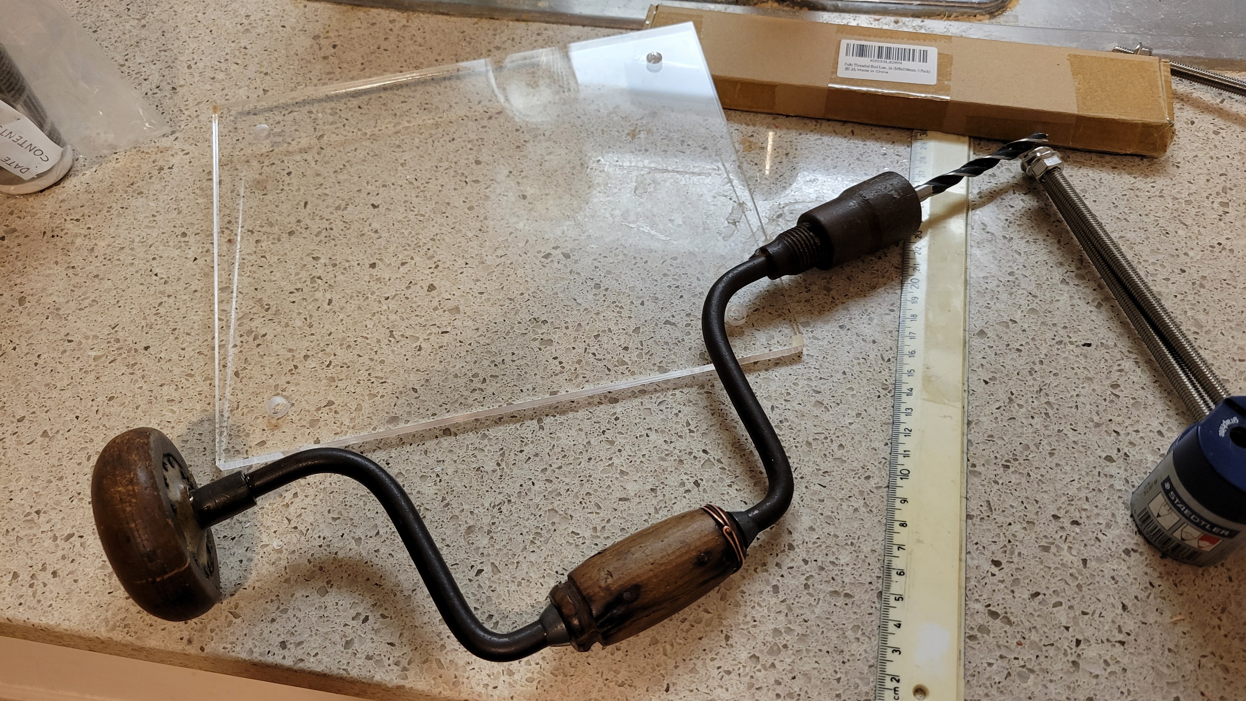
I know, I know this tool is prehistoric but it did its job without cracking anything ( It's my first time with acrylic so prefered to go slow... very slooooow)
------------------------------------------------------------------
I've added new commands to control micro positioner/stepper motor from software. Plus, I've added 'ring' command it to test piezoelectric discs connection. Although it's volume is low and nothing should be on piezoelectric discs it makes a noise and you can give a channel number {1,2,4,8}. This way you don't need signal generator.
------------------------------------------------------------------
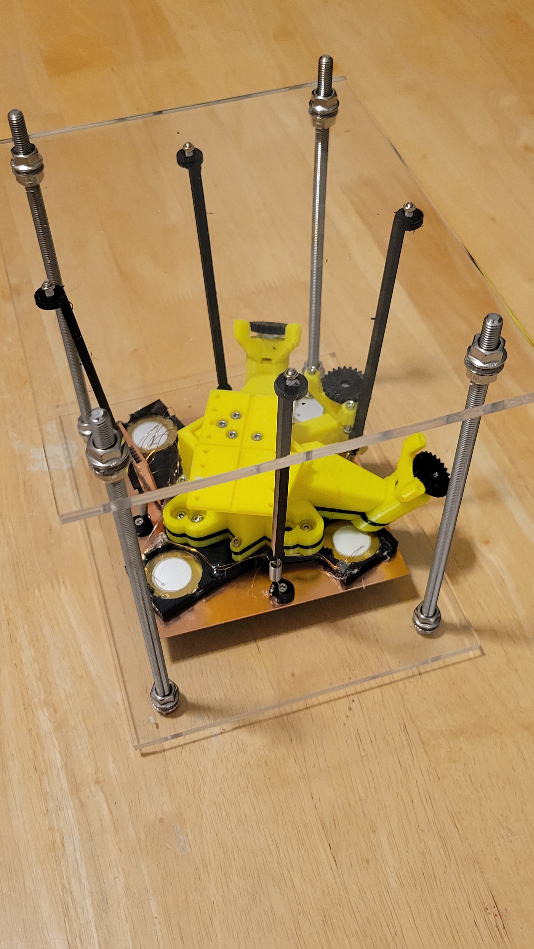
Added magnets and copper plate on top. This way we have Eddie currents that takes energy out of the system.
You can see that I've pushed them to the same starting position. The one with magnets stops very fast the other takes few seconds
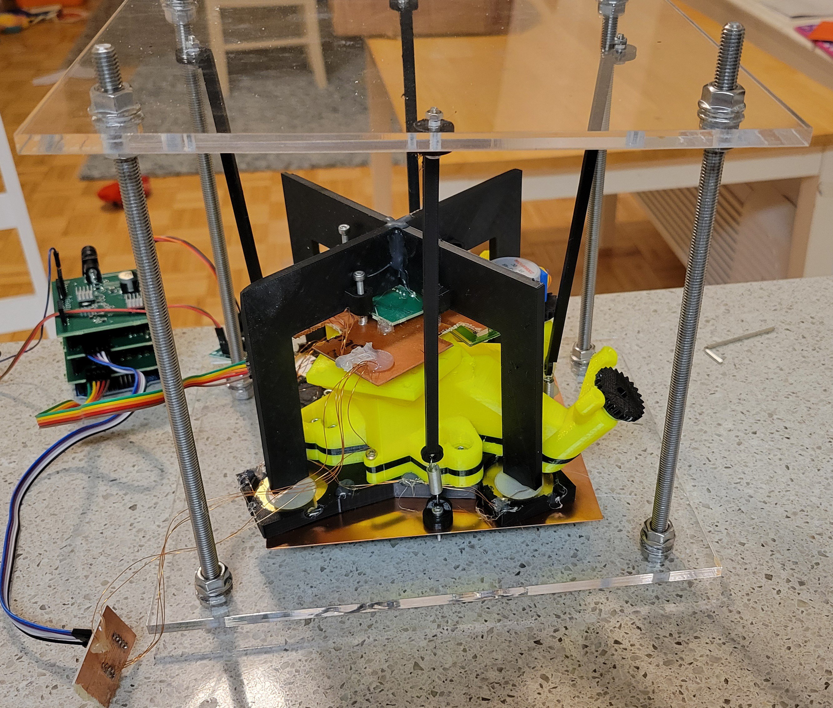
And this is how upgraded mechanical part looks like
-------------------------------------------------------------------
The micropositioner stepper motor worked better than I thought. I was able to run with 10 steps and even 1 step at a time to make 'approach', step that was super annoying to do manually. The accuracy is amazing I was running with 10 step hops it was so small I could not see the change only after a while I could see. ( I was looking through my cheap but long distance microscope).
Interesting thing I found is if I run small hops (less than 16 steps at a time) micropositioner goes back a little. This is not happening if 16 or 32 steps at a time used.
When this happens it usually takes 3 steps to get back to a point it's touching the surface.
Now what is really amazing is it takes about 10,000 nano-positioner steps to get back those 3 micropositioner steps. Each micropositioner steps is about 5 degrees devided by 64 (from stepper motor specs).
I finally solved the creep issue, after learning more about phenomenon I've found this graph
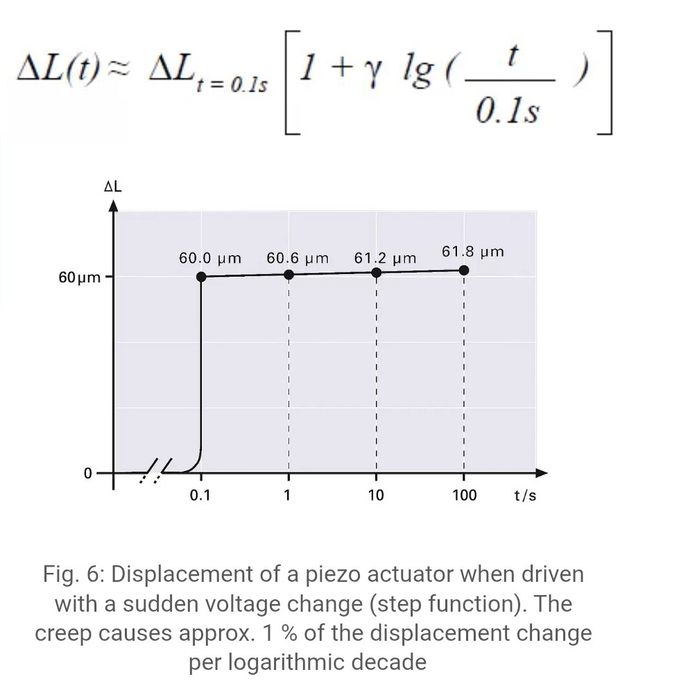
So, what I have it's not a creep, creep should be about 1%. So, I've suspected in the tiny connection wires of quartz forks. Could it bend each time it touches the surface?
To test it, I found an old quartz fork that was glued to the usb PCB plate.
Since I've solved electrical issue (by connecting plate to ground) I was able to use this one.
Ta-Da!!! It's working as a charm. No creep issue at all (even after going 3k steps down and back)!!! Now all is left is to connect vibration reduction and hope for the best....
-------------------------------------------------------------------
Finally the moment we all waited for so long. Everything is connected including vibration reduction system.
Note: I had to take a piece of PCB in order to fit it into vibration reduction system.
Now, I've followed the same procedure. Approach, few times getting closer and then scan. For now I scan only on one axis, so it easily to debug without the need of copying contacting etc. Plus, I prefer to do step by step.
The results were better than I expected.
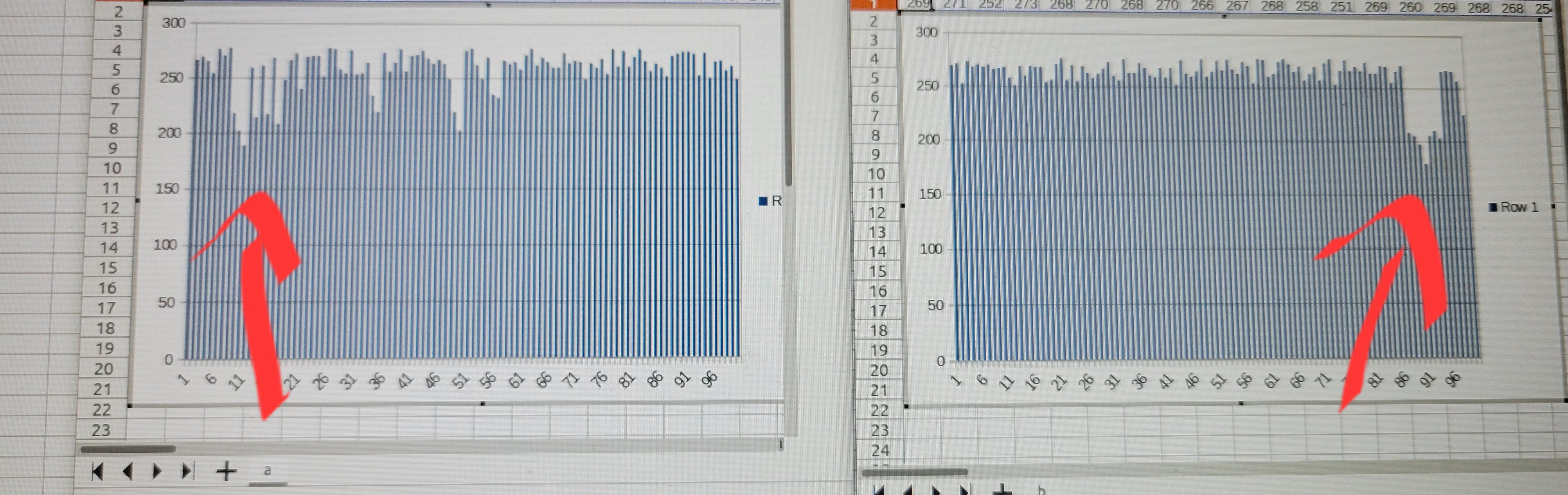
Here is two scans from same point in the sample. one from right to left and second from left to right. You can see the same notch in opposite places.
The 250 is where touching something and about 200 is where nothing detected. This is not a noise as noise is much smaller in range of 5-10.
The graph is quite binary but it can be much smoother when I will reduce the steps from 10 to 1 per hop. ( I've used steps of 10 so more surface would be scanned [I want amplification better than optical but I am not interested in seeing atoms at this point])
The next step would be writing Python based GUI. With GUI we could see 2D images of data.
Discussions
Become a Hackaday.io Member
Create an account to leave a comment. Already have an account? Log In.