-
1Design & Construction Details
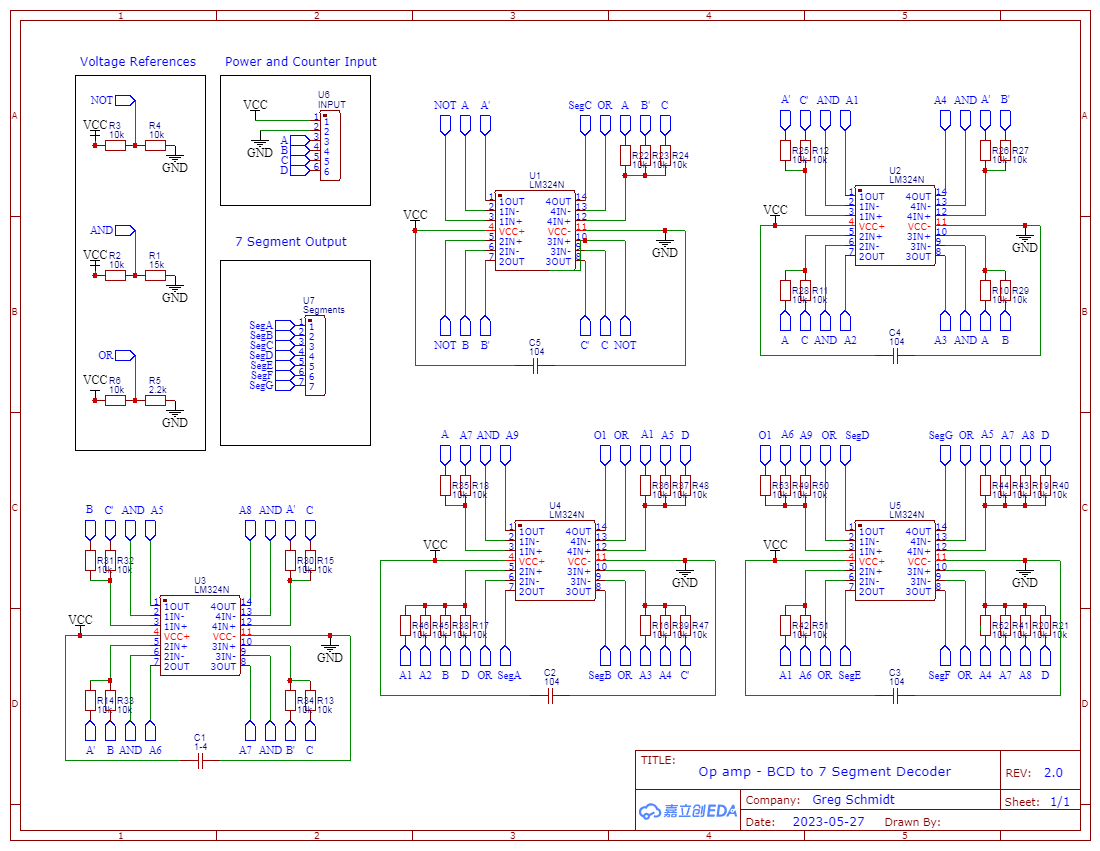
I used EasyEDA to layout the schematic. Unfortunately, I was too close to the deadline to order a double sided board so I ended up making my own single sided board in "old school" fashion.
![]()
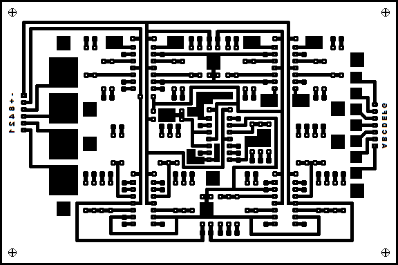
This is the board artwork. I used MS Paint to create this image!
![]()
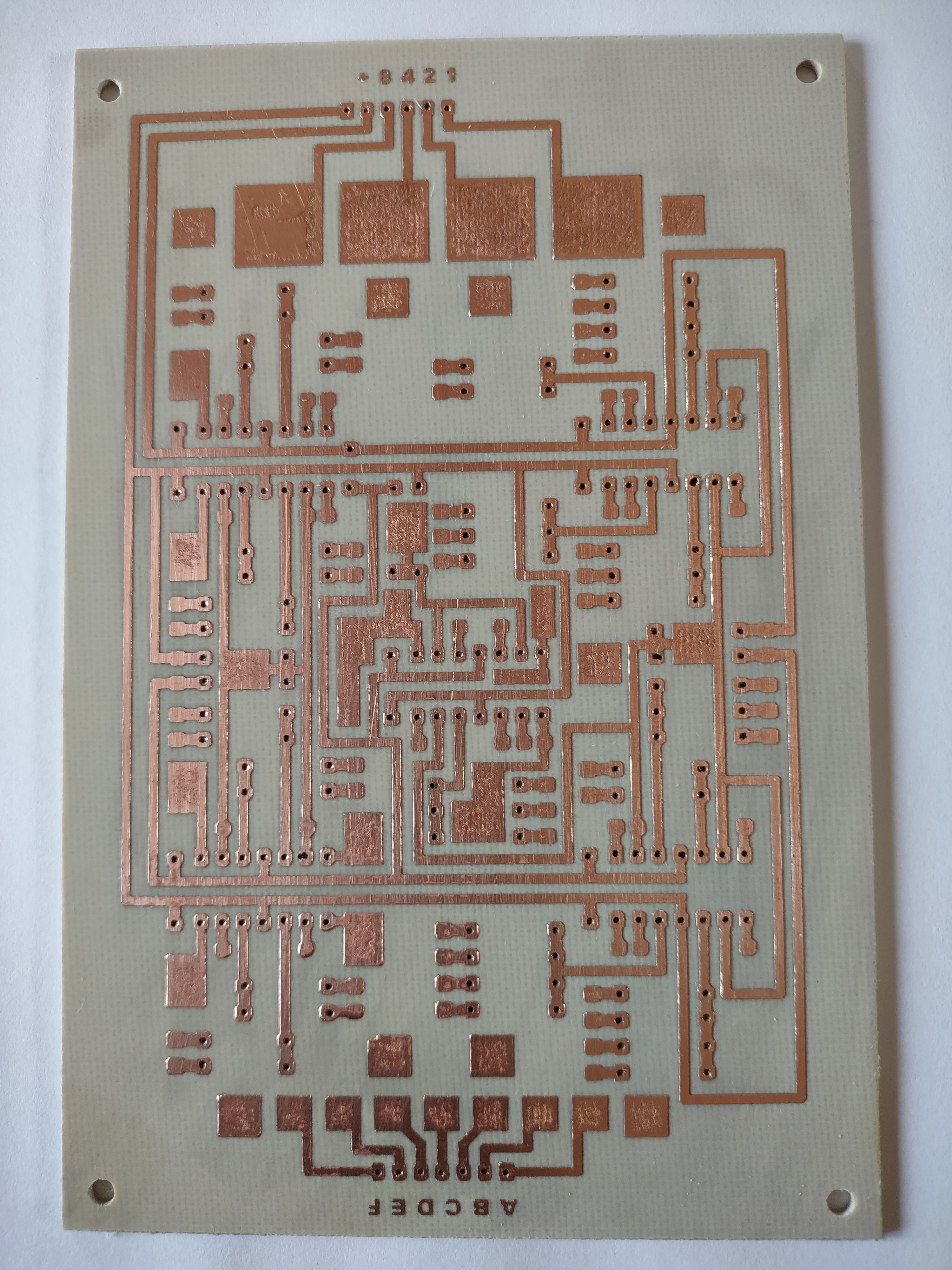
I used a laser printer to print the artwork onto magazine paper. I then transferred the toner from the paper onto the copper with a hot iron and and then etched the board with a mix of HCL (Muriatic acid) and Hydrogen Peroxide. Here is the result after drilling:
![]()
There are many more connection to be made that can be easily accomodated by a single sided board, so I designed it with pads so that I could solder (many) point to point wires.
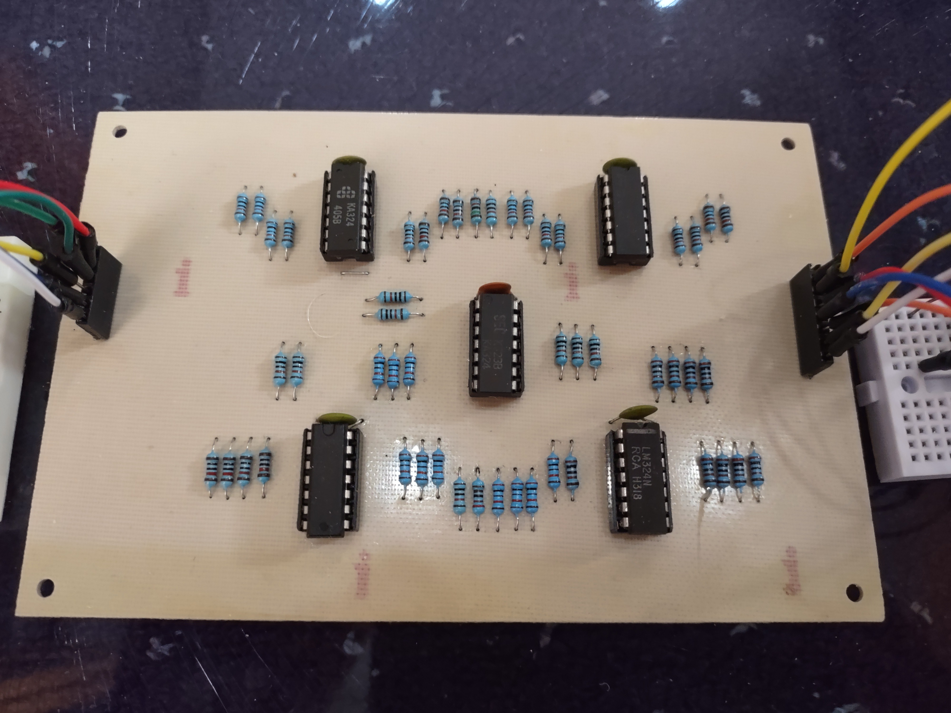
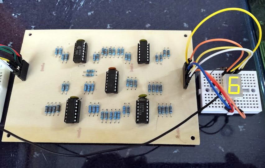
Here is the component side:
![]()
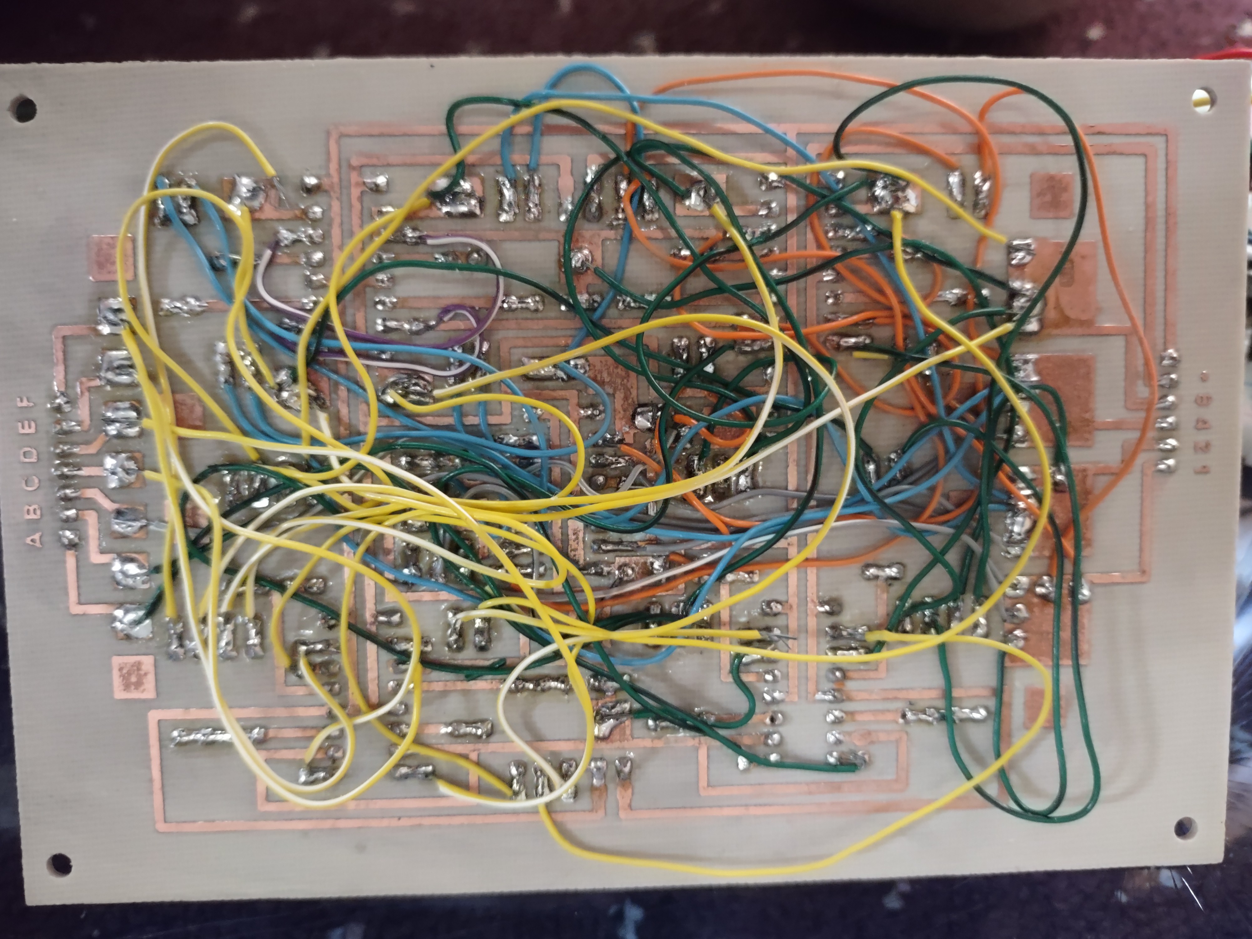
And here is the "rats nest" of point to point wiring on the copper side. I tested each chip with a multimeter after wiring it in order to find any errors early on and to avoid having to test it all at once.
![]()
After completing the wiring, I was pleased and a bit surprised to see that it appeared to be working!
I like to use salvaged components as much as possible in my builds. The wiring is old telephone wire, and the LM324's were removed from old electronics about to be recycled.
For the demo, the BCD inputs are being driven by a 74HC393 clocked by a 555 timer. On the output side, I connected a common anode 7 segment LED display.
![]()
OP-Amps Gone Digital - A BCD to 7 Seg Converter
A proof of concept which demonstrates how analog op amps can perform digital logic functions.
Discussions
Become a Hackaday.io Member
Create an account to leave a comment. Already have an account? Log In.