-
S-ROV Main Controller Design
01/09/2017 at 09:40 • 0 comments![]()
![]()
![]()
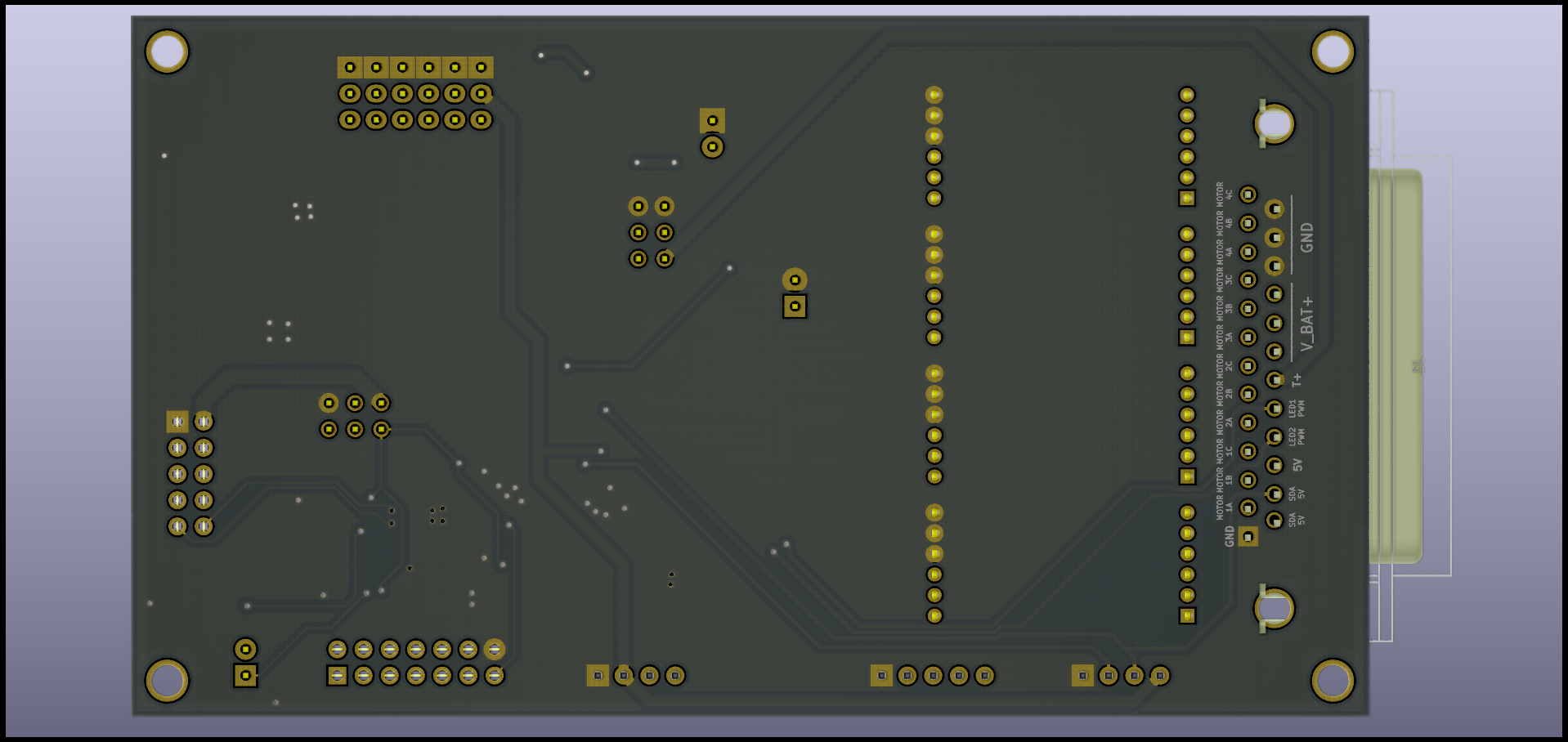
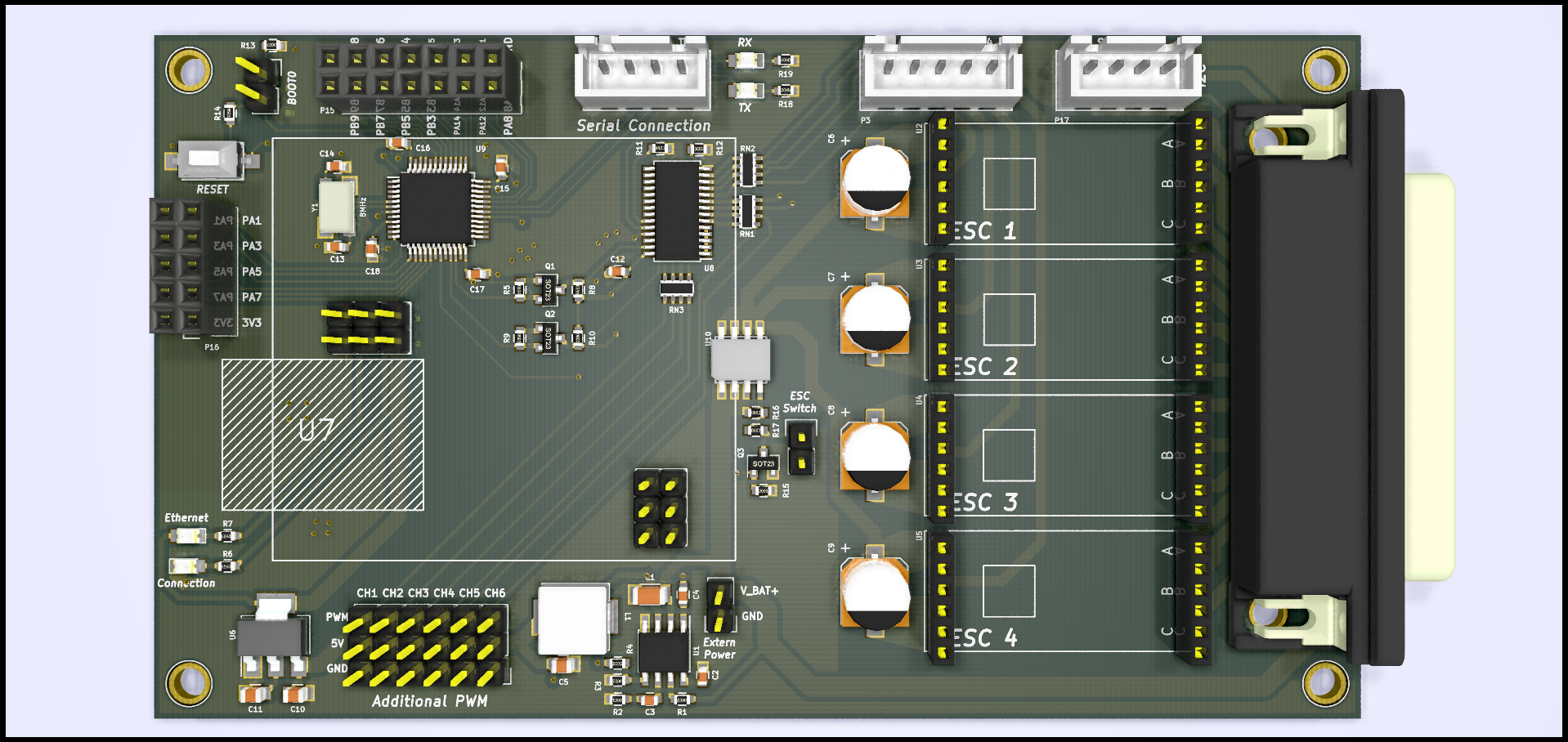
I designed ROV control PCB. It has STM32F103 MCU, and can be controlled by serial communication. Four ESC and PLC module can be attached. I will order this pcb tomorrow!
The open source for the circuit was released to github below.
-
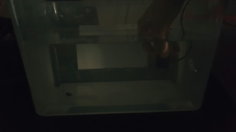
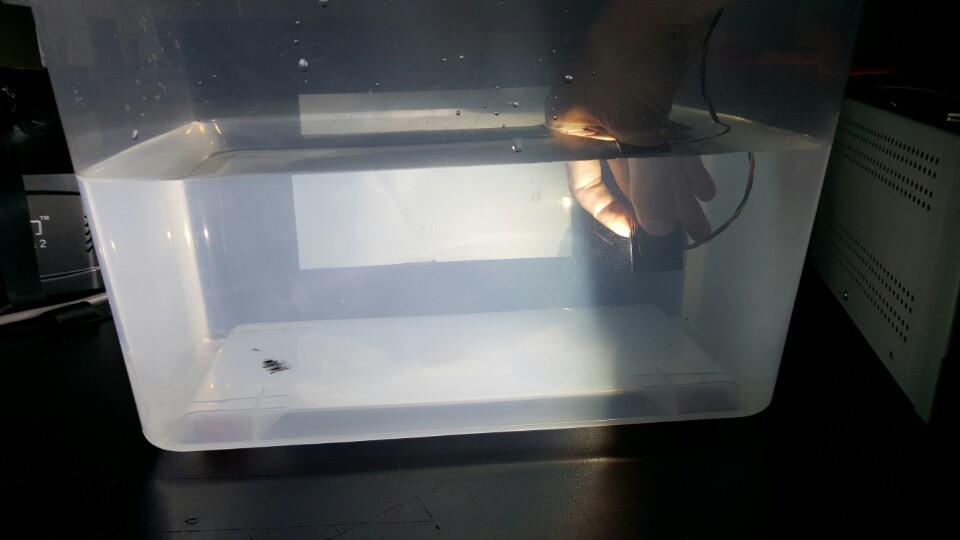
Testing LED Cube in water!
01/06/2017 at 09:48 • 0 comments -
Electronic System Configuration
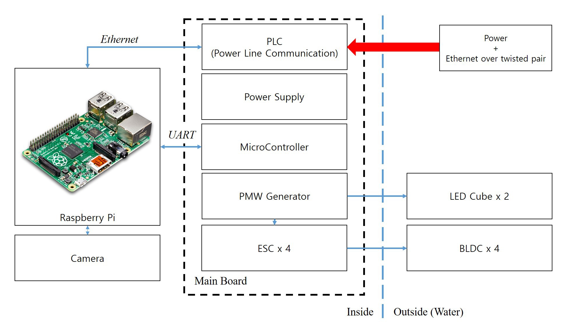
01/05/2017 at 16:13 • 0 commentsThe overall system of ROV that I am envisioning is as follows. In ROV operation, the main board plays the most central role. I'm currently determining the specifications, and they are almost decided.
![]()
- PLC(Power line communication)
Since ROV is a robot that operates in water, it can only be connected to the ground controller by wire. In order for ground users to communicate with the Raspberry pi inside the ROV, there must be an ethernet connection each other. However, in that case, up to 8 strands of wire should be needed. As the number of lines increases, it directly affects the ROV movement, and the system becomes bigger and the cost increases. So I decided to use PLC(Power Line Communication) for reduce the number of wires. In this case, we only need two pair of wire between rov and ground controller.
There are two PLC modules that we can obtain. First, OpenROV uses a board inside the home PLC module called 'tenda p200'. Second, there is a Fathom-X module used by BlueRobotics. In terms of performance, BlueRobotics' Fathom-X seems to be better, but considering the pricing and ease of purchase, I think it's better to use the Tenda P200 liek OpenROV.- ESC
![]() I'm currently designing the main board PCB, and it may be completed next week. :)
I'm currently designing the main board PCB, and it may be completed next week. :) -
S-ROV ledCube casing
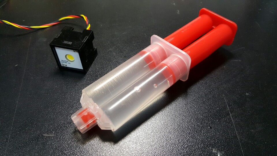
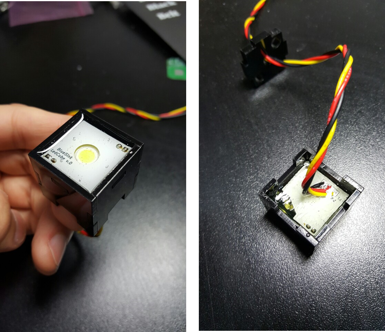
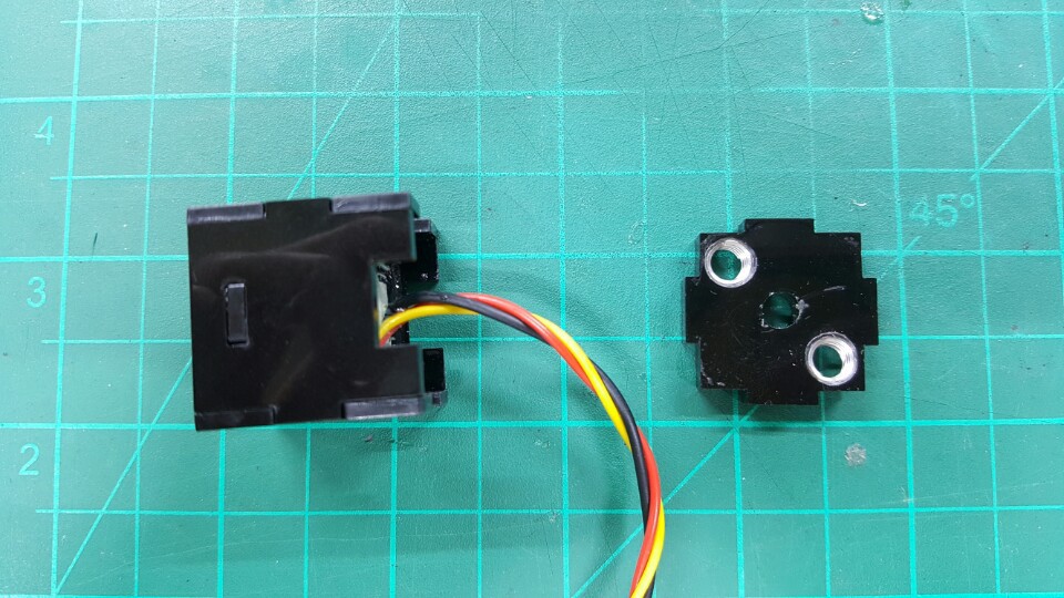
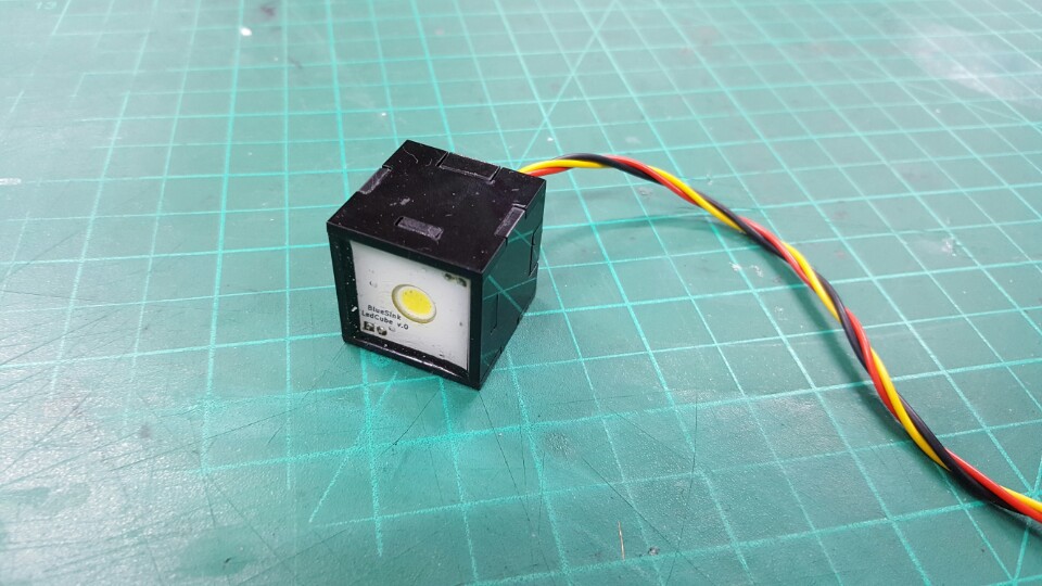
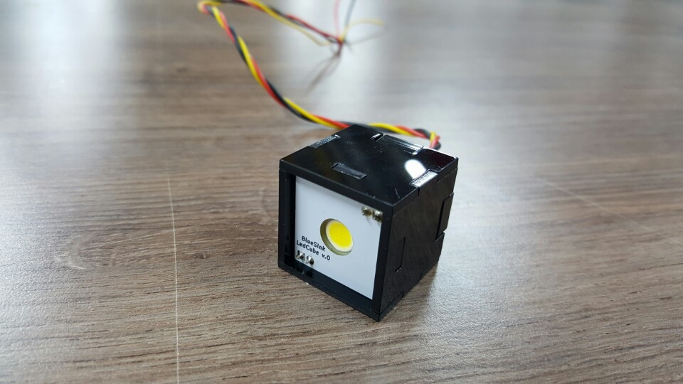
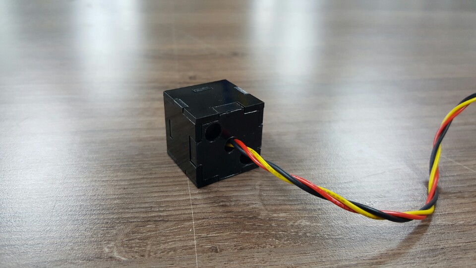
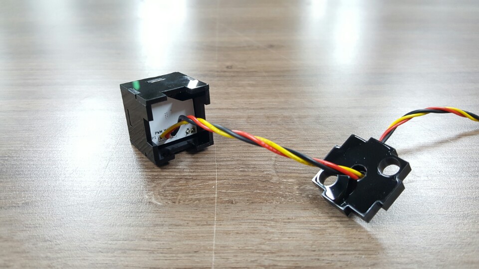
01/03/2017 at 10:39 • 0 commentsFor waterproofing ledCube pcb, I made a simple case using acrylic. The front of the case will be waterproofed with transparent epoxy and at the same time, the LED light will not be interfered. The interior is filled with thermally conductive epoxy to serve as an electronic waterproofing and heat conduction.
![]()
![]()
![]()
-
ledCube PCB setup & test
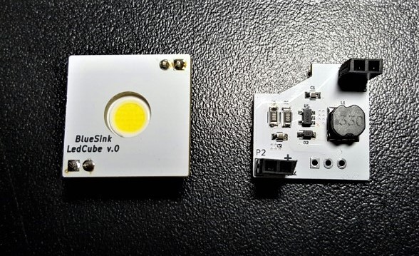
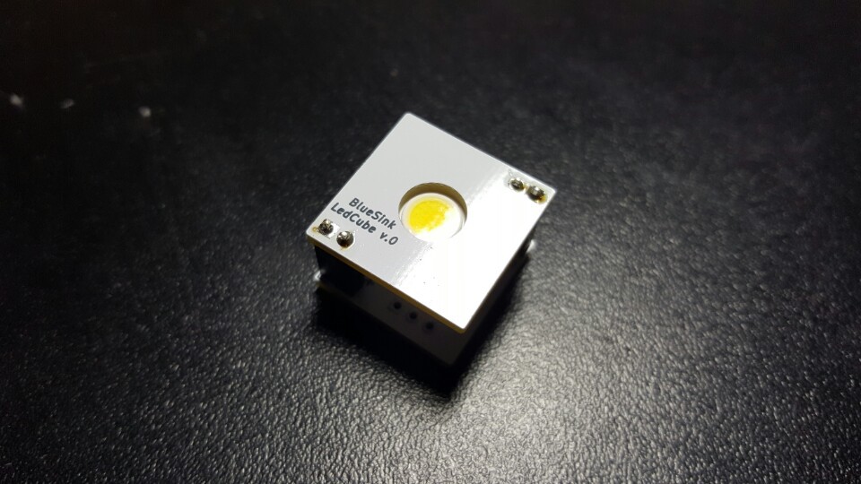
01/02/2017 at 07:21 • 0 commentsI just received PCB parts, and made the ledCube module. It has 2 pcb stacked sturcture. Power LED(CXA1304) is attached at the top, and led driver is installed at the bottom.
![]()
![]()
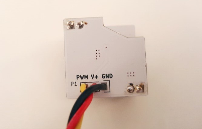
The power can be applied up to +36V, and the brightness of the LED can be adjusted by PWM of 3.3V and 5V.
Soon, I will casing the ledCube module, and test it in the water.![]()
-
Making S-ROV ledCube
12/30/2016 at 02:58 • 0 commentsWe will attach the led lighting device in front of the ROV. Since the tube which the electric devices are inserted is elongated in the front and back direction, the lighting device cannot enter the tube. So I'm thinking of placing it on the outside of the tube. The shape of it will be similar to the OpenROV Light Cube.
Also, we plan to put the led driver inside the cube so that the brightness can easily be controlled by simply inputting pwm from the outside. Once, I design the PCB and leave it to production, I will be able to test it by next Monday.
![]()
![]()
The follwoing links are used when I configure the led driver.
- Sparkfun - FemtoBuck LED Driver
- Protofusion pageAnd the source is available in github.
 YJ Kim
