A good article that explains in detail the PWM strategy is available on Wikipedia at https://en.wikipedia.org/wiki/Pulse-width_modulation.
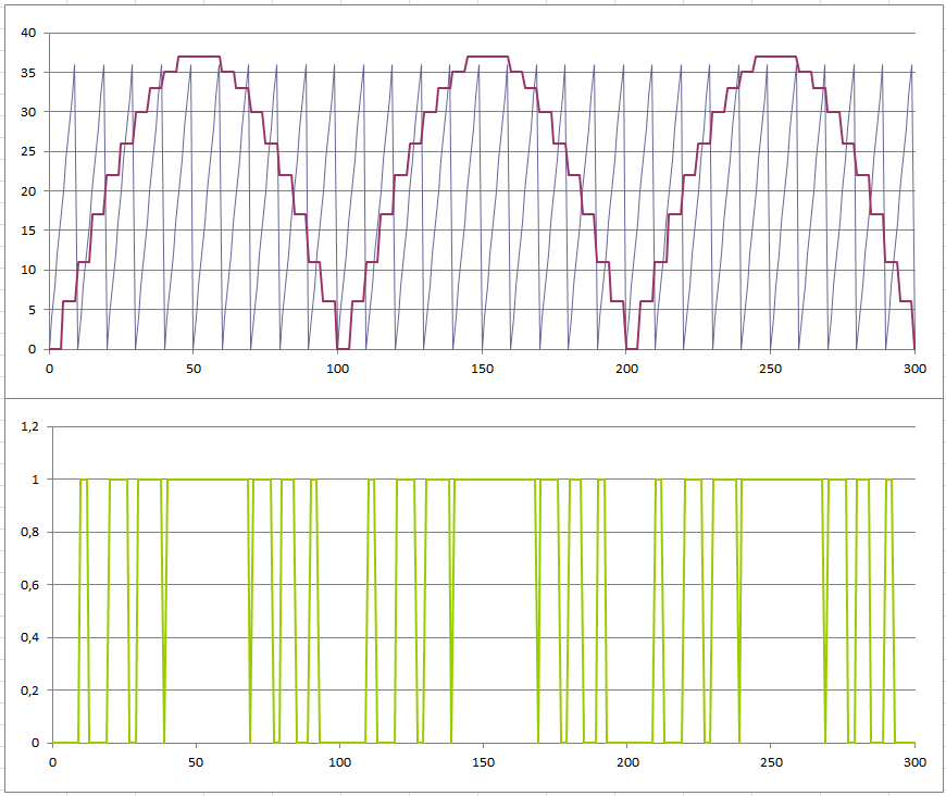
For now, the strategy adopted in this project is to compare the desired output signal (sine wave) with a reference signal, a sawtooth wave. When the latter is below the generator signal, the PWM is in high state (1). Otherwise it is in the low state (0). See the following figure.
It is not necessary to do this for the complete sine wave, just a half-cycle because of its symmetry. To achieve the negative half-cycle, one bit will toggle the switching sequence of H-bridge.
The 8051 does not have any facility to generate PWM outputs, so the strategy described should be made entirely in the code. To generate the sine and sawtooth waves, the two 8051 timers and their interrupts will be used.
The sine wave uses the lookup table technique. Let's see the code:
T0_INT:
	CLR TR0			;STOP THE TIMER
	MOV DPTR, #SINE_WAVE
	MOV A, COUNT_SIN
	MOVC A, @A+DPTR		;SEE THE VALUE OF COUNT_SIN INDEX IN THE SINE_WAVE TABLE
	MOV SINE, A		;AND STORE IN SINE VARIABLE

	MOV C, SINE.7		;HIGH BIT OF VALUE IS THE POLARITY
	MOV P1.1,C		;SEND IT TO THE OWN OUTPUT
	CLR SINE.7		;AND CLEAR IT

	INC COUNT_SIN		;GO TO NEXT VALUE
	MOV A, COUNT_SIN

	CJNE A, #40, QUIT_T0	;CHECK IF TABLE ARE AT THE END
	MOV COUNT_SIN, #0	;THEN, RESTART THE TABLE COUNT

QUIT_T0:
	MOV	TL0, T_SIN_L	;RELOAD THE TIMER COUNTER
	MOV	TH0, T_SIN_H
	SETB TR0		;RESTART THE TIMER
	RETI
Each time the interrupt is called, the current value of the wave is updated by querying a pre-calculated table. Considering that the time interval is equal, the wave is generated by the sequencing of values.
For the sawtooth wave the procedure is simpler: just increment the current value with constant step until it reaches the value of its period (10 steps), restarting the sequence. As the frequency is higher, it is possible to use the 8051 timer in 8-bit auto reload mode, simplifying the code. See the code:
T1_INT:
	;THE SAWTOOTH WAVE GENERATION
	MOV A, SAWTOOTH
	ADD A, STEP_SAW		;INCREMENT THE SAW WIHT CURRENT STEP
	MOV SAWTOOTH, A

	DJNZ COUNT_SAW, QUIT_T1	;CHECK IT'S DONE
	MOV SAWTOOTH, #0	;THEN, RESTART THE WAVE
	MOV COUNT_SAW, #10D	;AND RESET ITS COUNTER
QUIT_T1:
	RETI
Finally, the PWM output compares the two signals and the result will be the carry bit:
	MOV A,SAWTOOTH		;COMPARES THE SAW WAVE
	SUBB A,SINE		;VERSUS THE SINE WAVE
	MOV P1.0,C		;<==== PMW OUTPUT
Putting everything together (PWM shares the sawtooth timer):
;===== SINE WAVE GENERATION =======
;THE SINE WAVE IS USED AS A COMPARATIVE REFERENCE IN THE PWM OUTPUT.
;THE SINE VALUE IS PERIODICALLY UPDATED BY T0 INTERRUPTION CALL,
;VIA LOOKUP TABLE TECHNIQUE. THE TIME OF INTERRUPTION VARIES,
;DEPENDING ON THE SELECTED OUTPUT FREQ.

T0_INT:
	CLR TR0			;STOP THE TIMER
	MOV DPTR, #SINE_WAVE
	MOV A, COUNT_SIN
	MOVC A, @A+DPTR		;SEE THE VALUE OF COUNT_SIN INDEX IN THE SINE_WAVE TABLE
	MOV SINE, A		;AND STORE IN SINE VARIABLE

	MOV C, SINE.7		;HIGH BIT OF VALUE IS THE POLARITY
	MOV P1.1,C		;SEND IT TO THE OWN OUTPUT
	CLR SINE.7		;AND CLEAR IT

	INC COUNT_SIN		;GO TO NEXT VALUE
	MOV A, COUNT_SIN

	CJNE A, #40, QUIT_T0	;CHECK IF TABLE ARE AT THE END
	MOV COUNT_SIN, #0	;THEN, RESTART THE TABLE COUNT

QUIT_T0:
	MOV	TL0, T_SIN_L	;RELOAD THE TIMER COUNTER
	MOV	TH0, T_SIN_H
	SETB TR0		;RESTART THE TIMER
	RETI

;===== SAW WAVE GENERATION  AND PWM OUTPUT =======
;THE FREQUENCY OF SAWTHOOTH WAVE IS FIXED AT 1200Hz,
;AND THIS SIGNAL IS GENERATE WITH 10 STEPS.

T1_INT:
	;FIRST, THE PWM!
	MOV A,SAWTOOTH		;COMPARES THE SAW WAVE
	SUBB A,SINE		;VERSUS THE SINE WAVE
	MOV P1.0,C		;<==== PMW OUTPUT

	;CONTINUE THE SAWTOOTH WAVE GENERATION
	MOV A, SAWTOOTH
	ADD A, STEP_SAW		;INCREMENT THE SAW WIHT CURRENT STEP
	MOV SAWTOOTH, A

	DJNZ COUNT_SAW, QUIT_T1	;CHECK IT'S DONE
	MOV SAWTOOTH, #0	;THEN, RESTART THE WAVE
	MOV COUNT_SAW, #10D	;AND RESET ITS COUNTER
QUIT_T1:
	DEC R0			;R0 FOR BUTTON DEBOUNCE ROUTINE
	RETI
 Ezequiel
Discussions
Become a Hackaday.io Member
Create an account to leave a comment. Already have an account? Log In.