Hello, this is my first project in Hackaday.io. I'm from Brazil and first apologize for bad English, but it's not my native language.
Well, this project aims to make an inverter for induction motors with V / f control. The core control is based on the standard 8051 architecture. For ease of construction, I will use an AT89C2051 chip.
Base characteristics:
- 8051 architecture;
- Assembly language;
- Drive based on H bridge;
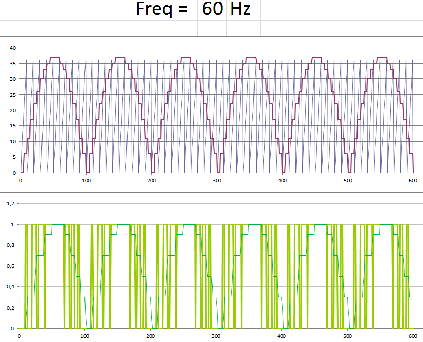
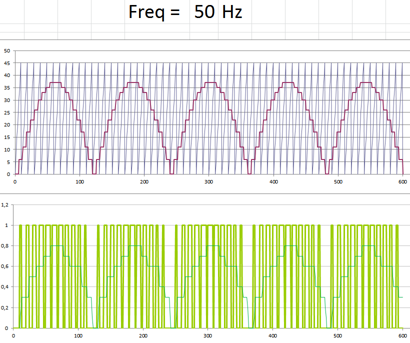
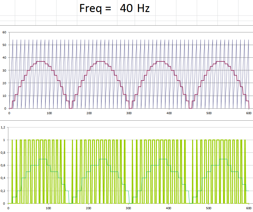
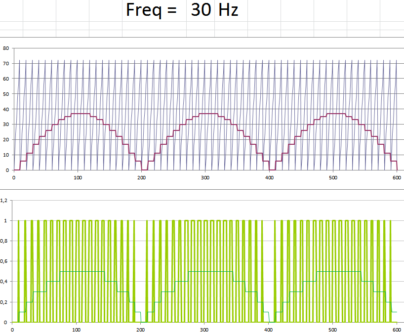
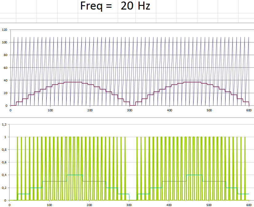
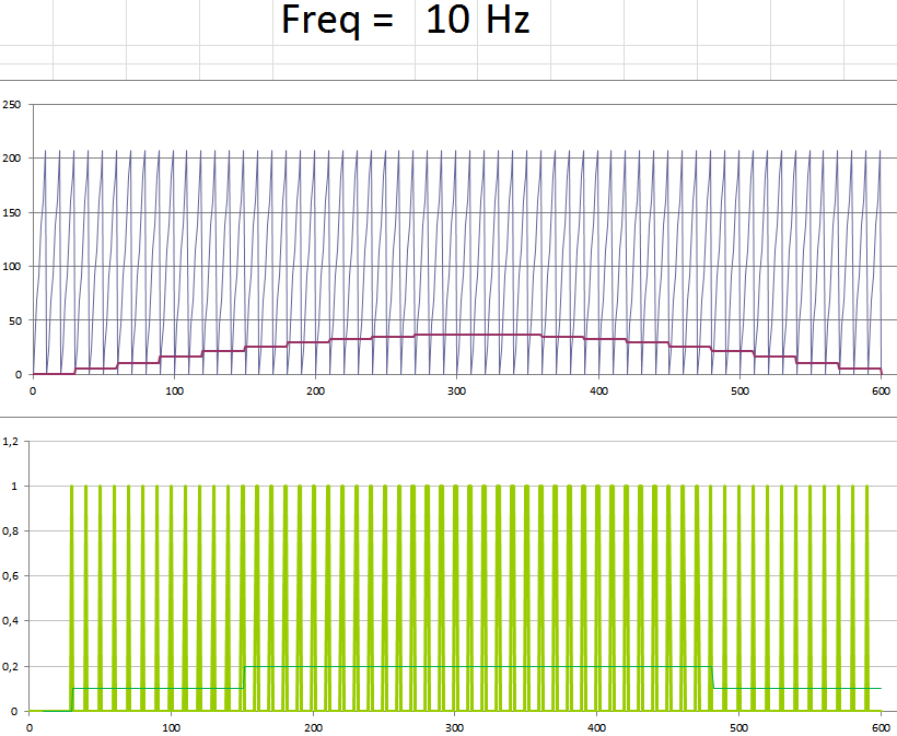
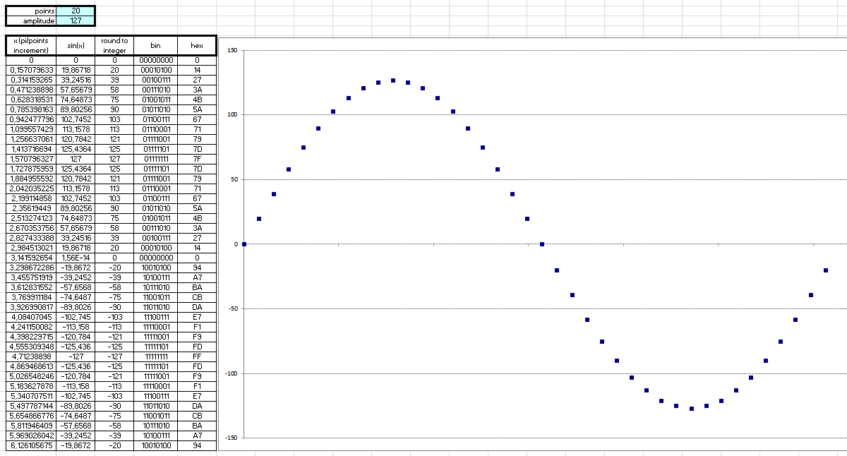
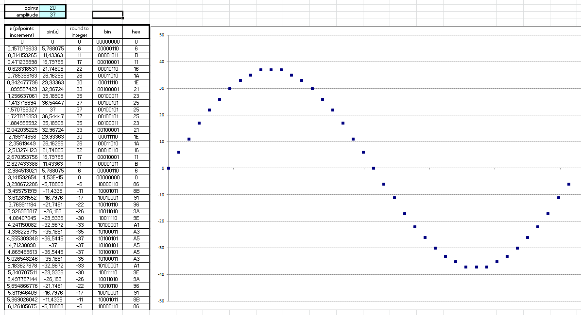
- Sine wave output, via PWM control;
- V / f control to maintain constant the torque curve in the motor, with the frequency variation;
- Output frequencies available: 60, 50, 40, 30, 20 and 10Hz.
- Simple interface, with one button and a few LEDs for indication.
 Ezequiel