 Ezequiel
To make the sine wave table used in the algorithm shown in the last post, a spreadsheet was used to help calculate the values (this is in the file area, see "sine" tab in calc.xls).
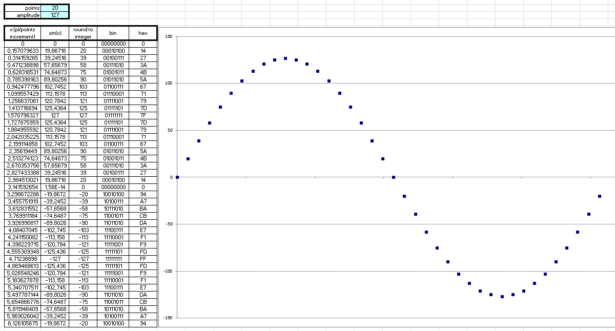
Each half-cycle of the wave was sampled at 20 points, and the amplitude was limited so that the values fit into 8-bit words. The higher bit in the word is the polarity and the other 7 is the value itself, which determines that the amplitude is 127 max. This resulted in a good waveform even with integer values. See the following figure:
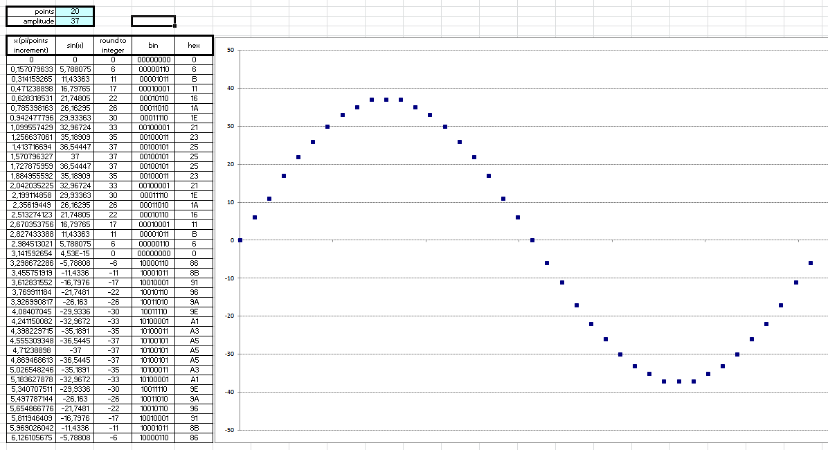
To implement the V/f control strategy (we'll see later), the wave amplitude had to be set to 37 max (trial and error). But this did not significantly impair the waveform. See the following figure:
 Then the final table in the code:
;======== SINE WAVE TABLE ==================
;FULL CYCLE OF SINE WAVE, SAMPLED AT 40 POINTS
;MOST SIGNIFICANT BIT INDICATES NEGATIVE POLARITY
SINE_WAVE:
	DB 0,6,11,17,22,26,30,33,35,37,37,37,35,33,30,26,22,17,11,6,0,134,139,145,150,154,158,161,163,165,165,165,163,161,158,154,150,145,139,134

;======================================
Discussions
Become a Hackaday.io Member
Create an account to leave a comment. Already have an account? Log In.