Ezequiel
-
The V/f Strategy
01/05/2017 at 16:30 • 0 commentsSome good articles explaining the speed control of induction motors via V / f strategy are available in:
http://www.electrical4u.com/variable-frequency-drive/
http://controltrends.org/wp-content/uploads/2010/10/VFFundamentals.pdf
In this project, I tried to prevent the microcontroller from performing calculations for voltage and frequency variables. It uses pre-calculated values to load the registers used in the routines, according to the desired output frequency. I will show how these values were obtained (see the spreadsheet with the calculations on the "v-f" tab).
First the frequency. To change the output frequency simply adjust the sine wave refresh rate, ie change the reload value of the timer 0 interrupt counter (variables T_SIN_H and T_SIN_L, which represent the 16-bit word). For more details, refer to the spreadsheet and the 8051 manual, remembering that the timer is in mode 1. The calculated values are shown below.
;VALUES TO BE RELOADED IN SINE´S TIMER, ACCORDING TO THE FREQUENCY
    T_60 EQU 65152D
    T_50 EQU 65075D
    T_40 EQU 64960D
    T_30 EQU 64768D
    T_20 EQU 64384D
    T_10 EQU 63232D
To change the voltage, the option with less calculations in the microcontroller is to vary the amplitude of the sawtooth wave. This is done by changing the step of increasing the timer interrupt 1 (variable STEP_SAW). The variation behavior is inverse, that is, by increasing the wave amplitude, it will be reducing the output voltage.
In this case, the challenges were: to find integer increments that produced good resolution in the tension variation; And ensure that the amplitude of the saw is less than or equal to 255 (to fit into an 8-bit word) at all output frequencies. By trial and error method, all parameters had to be adjusted to respect these conditions (including the sine amplitude, 37, remember?). The calculated values are shown below.
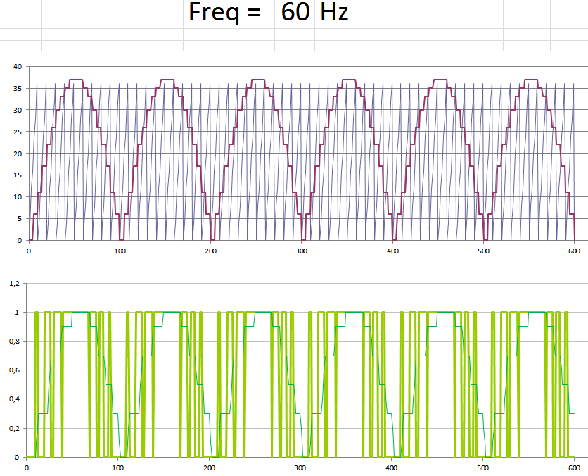
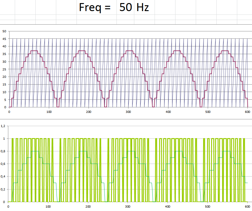
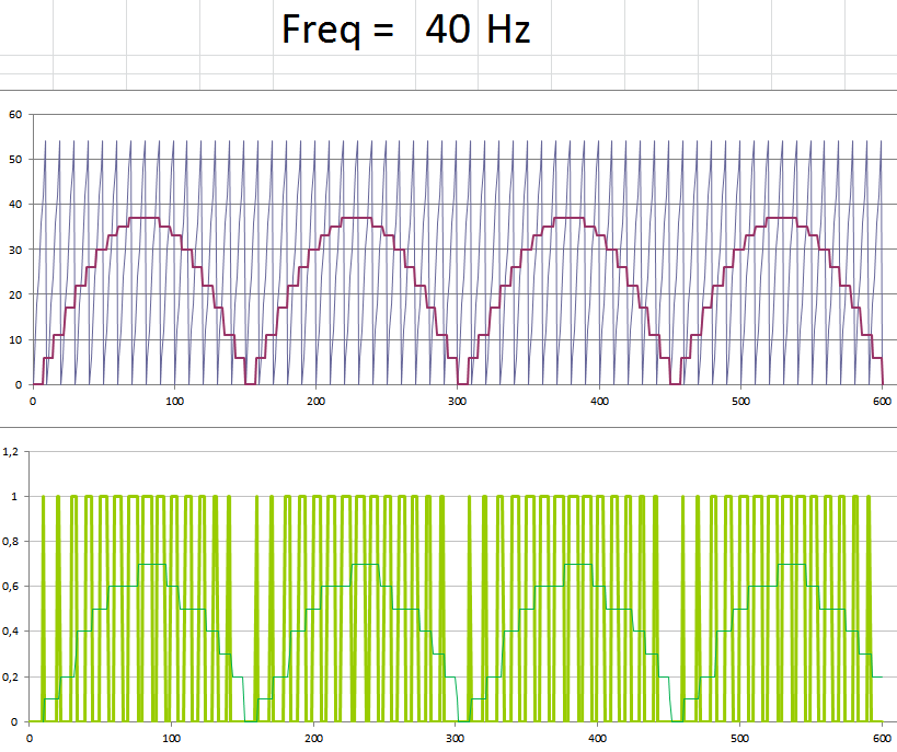
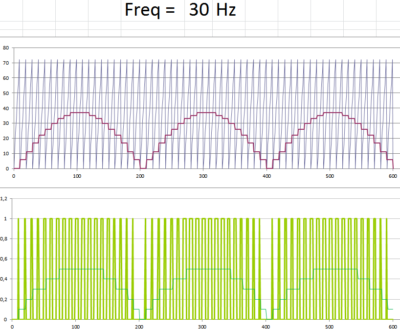
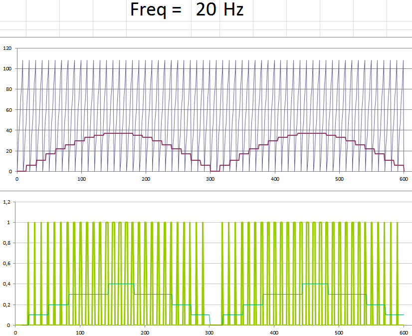
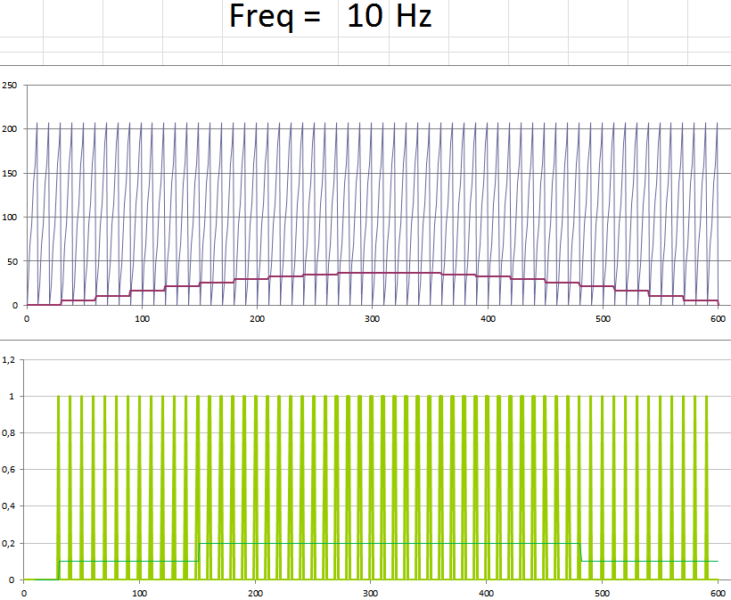
;VALUES OF THE AMPLITUDE STEP OF THE SAWTOOTH WAVE, ACCORDING TO THE FREQUENCY
	STEP_60 EQU 4D
	STEP_50 EQU 5D
	STEP_40 EQU 6D
	STEP_30 EQU 8D
	STEP_20 EQU 11D
	STEP_10 EQU 23D
A simulation of the full PWM output can be seen in the "pwm" tab of the worksheet. The following figures show the results (at 10Hz is poor, but acceptable)
![]()
![]()
![]()
![]()
![]()
![]()
-
The Sine Table
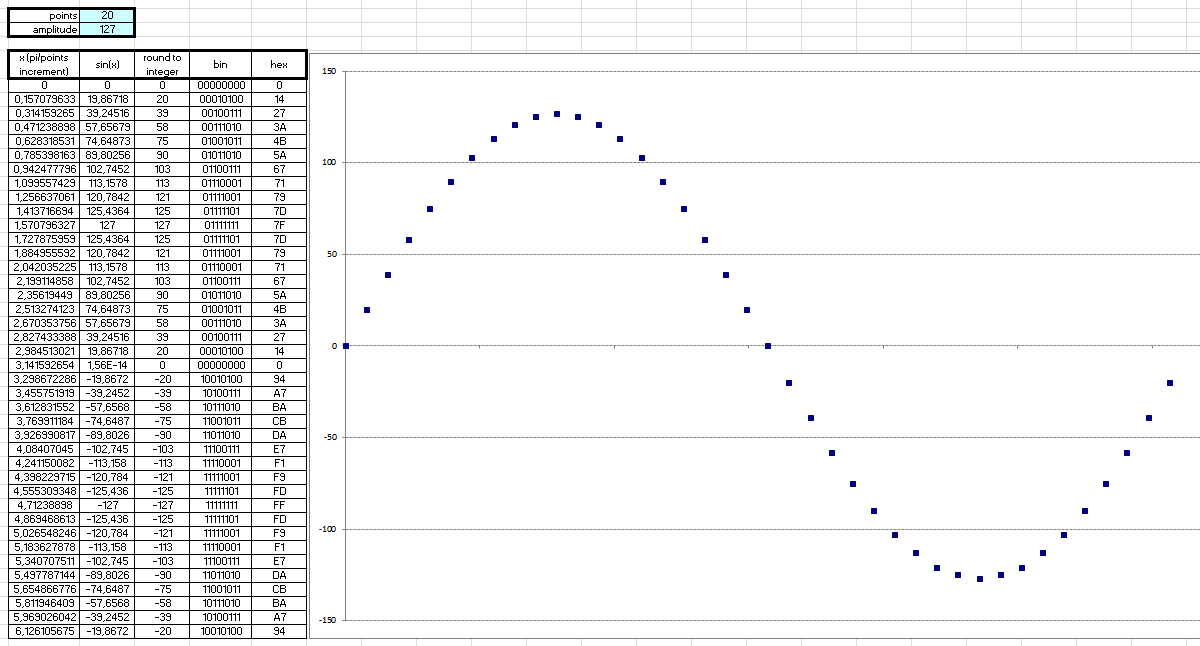
01/04/2017 at 10:54 • 0 commentsTo make the sine wave table used in the algorithm shown in the last post, a spreadsheet was used to help calculate the values (this is in the file area, see "sine" tab in calc.xls).
Each half-cycle of the wave was sampled at 20 points, and the amplitude was limited so that the values fit into 8-bit words. The higher bit in the word is the polarity and the other 7 is the value itself, which determines that the amplitude is 127 max. This resulted in a good waveform even with integer values. See the following figure:
![]()
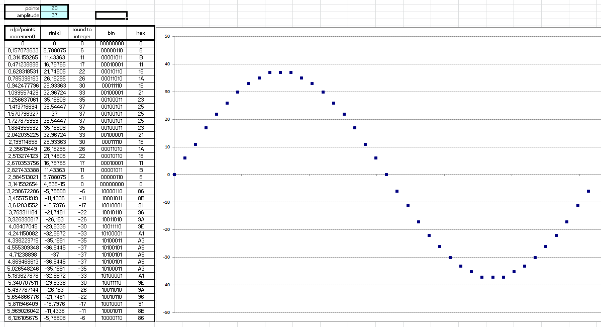
To implement the V/f control strategy (we'll see later), the wave amplitude had to be set to 37 max (trial and error). But this did not significantly impair the waveform. See the following figure:
![]() Then the final table in the code:
Then the final table in the code:;======== SINE WAVE TABLE ================== ;FULL CYCLE OF SINE WAVE, SAMPLED AT 40 POINTS ;MOST SIGNIFICANT BIT INDICATES NEGATIVE POLARITY SINE_WAVE: DB 0,6,11,17,22,26,30,33,35,37,37,37,35,33,30,26,22,17,11,6,0,134,139,145,150,154,158,161,163,165,165,165,163,161,158,154,150,145,139,134 ;======================================
-
The PWM
01/02/2017 at 16:07 • 0 commentsA good article that explains in detail the PWM strategy is available on Wikipedia at https://en.wikipedia.org/wiki/Pulse-width_modulation.
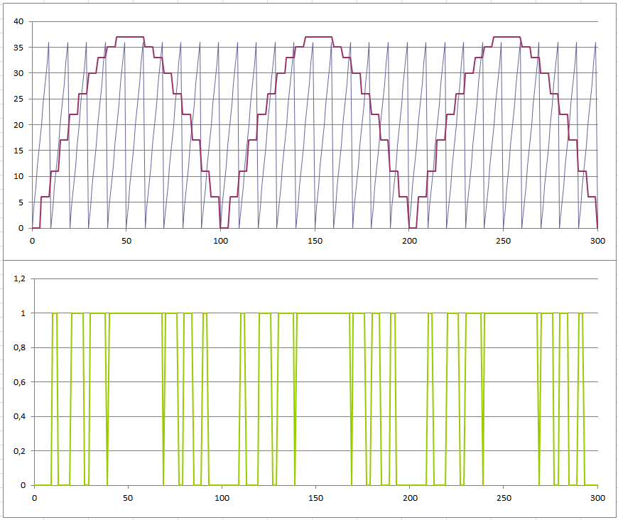
For now, the strategy adopted in this project is to compare the desired output signal (sine wave) with a reference signal, a sawtooth wave. When the latter is below the generator signal, the PWM is in high state (1). Otherwise it is in the low state (0). See the following figure.
![]()
It is not necessary to do this for the complete sine wave, just a half-cycle because of its symmetry. To achieve the negative half-cycle, one bit will toggle the switching sequence of H-bridge.
The 8051 does not have any facility to generate PWM outputs, so the strategy described should be made entirely in the code. To generate the sine and sawtooth waves, the two 8051 timers and their interrupts will be used.
The sine wave uses the lookup table technique. Let's see the code:
T0_INT:
	CLR TR0			;STOP THE TIMER
	MOV DPTR, #SINE_WAVE
	MOV A, COUNT_SIN
	MOVC A, @A+DPTR		;SEE THE VALUE OF COUNT_SIN INDEX IN THE SINE_WAVE TABLE
	MOV SINE, A		;AND STORE IN SINE VARIABLE

	MOV C, SINE.7		;HIGH BIT OF VALUE IS THE POLARITY
	MOV P1.1,C		;SEND IT TO THE OWN OUTPUT
	CLR SINE.7		;AND CLEAR IT

	INC COUNT_SIN		;GO TO NEXT VALUE
	MOV A, COUNT_SIN

	CJNE A, #40, QUIT_T0	;CHECK IF TABLE ARE AT THE END
	MOV COUNT_SIN, #0	;THEN, RESTART THE TABLE COUNT

QUIT_T0:
	MOV	TL0, T_SIN_L	;RELOAD THE TIMER COUNTER
	MOV	TH0, T_SIN_H
	SETB TR0		;RESTART THE TIMER
	RETI
Each time the interrupt is called, the current value of the wave is updated by querying a pre-calculated table. Considering that the time interval is equal, the wave is generated by the sequencing of values.
For the sawtooth wave the procedure is simpler: just increment the current value with constant step until it reaches the value of its period (10 steps), restarting the sequence. As the frequency is higher, it is possible to use the 8051 timer in 8-bit auto reload mode, simplifying the code. See the code:
T1_INT:
	;THE SAWTOOTH WAVE GENERATION
	MOV A, SAWTOOTH
	ADD A, STEP_SAW		;INCREMENT THE SAW WIHT CURRENT STEP
	MOV SAWTOOTH, A

	DJNZ COUNT_SAW, QUIT_T1	;CHECK IT'S DONE
	MOV SAWTOOTH, #0	;THEN, RESTART THE WAVE
	MOV COUNT_SAW, #10D	;AND RESET ITS COUNTER
QUIT_T1:
	RETI
Finally, the PWM output compares the two signals and the result will be the carry bit:
	MOV A,SAWTOOTH		;COMPARES THE SAW WAVE
	SUBB A,SINE		;VERSUS THE SINE WAVE
	MOV P1.0,C		;<==== PMW OUTPUT
Putting everything together (PWM shares the sawtooth timer):
;===== SINE WAVE GENERATION =======
;THE SINE WAVE IS USED AS A COMPARATIVE REFERENCE IN THE PWM OUTPUT.
;THE SINE VALUE IS PERIODICALLY UPDATED BY T0 INTERRUPTION CALL,
;VIA LOOKUP TABLE TECHNIQUE. THE TIME OF INTERRUPTION VARIES,
;DEPENDING ON THE SELECTED OUTPUT FREQ.

T0_INT:
	CLR TR0			;STOP THE TIMER
	MOV DPTR, #SINE_WAVE
	MOV A, COUNT_SIN
	MOVC A, @A+DPTR		;SEE THE VALUE OF COUNT_SIN INDEX IN THE SINE_WAVE TABLE
	MOV SINE, A		;AND STORE IN SINE VARIABLE

	MOV C, SINE.7		;HIGH BIT OF VALUE IS THE POLARITY
	MOV P1.1,C		;SEND IT TO THE OWN OUTPUT
	CLR SINE.7		;AND CLEAR IT

	INC COUNT_SIN		;GO TO NEXT VALUE
	MOV A, COUNT_SIN

	CJNE A, #40, QUIT_T0	;CHECK IF TABLE ARE AT THE END
	MOV COUNT_SIN, #0	;THEN, RESTART THE TABLE COUNT

QUIT_T0:
	MOV	TL0, T_SIN_L	;RELOAD THE TIMER COUNTER
	MOV	TH0, T_SIN_H
	SETB TR0		;RESTART THE TIMER
	RETI

;===== SAW WAVE GENERATION  AND PWM OUTPUT =======
;THE FREQUENCY OF SAWTHOOTH WAVE IS FIXED AT 1200Hz,
;AND THIS SIGNAL IS GENERATE WITH 10 STEPS.

T1_INT:
	;FIRST, THE PWM!
	MOV A,SAWTOOTH		;COMPARES THE SAW WAVE
	SUBB A,SINE		;VERSUS THE SINE WAVE
	MOV P1.0,C		;<==== PMW OUTPUT

	;CONTINUE THE SAWTOOTH WAVE GENERATION
	MOV A, SAWTOOTH
	ADD A, STEP_SAW		;INCREMENT THE SAW WIHT CURRENT STEP
	MOV SAWTOOTH, A

	DJNZ COUNT_SAW, QUIT_T1	;CHECK IT'S DONE
	MOV SAWTOOTH, #0	;THEN, RESTART THE WAVE
	MOV COUNT_SAW, #10D	;AND RESET ITS COUNTER
QUIT_T1:
	DEC R0			;R0 FOR BUTTON DEBOUNCE ROUTINE
	RETI
-
Code and Schematics
12/31/2016 at 13:30 • 0 commentsThe full source is available in the file area and also in GitHub, and is well commented (the translation may not be very good). The code is fully functional, but may change in the future.
Circuit schematics are also available. The control circuit is based on the AT89C2051 which for me is quite easy to use and assemble. But the code is fully compatible with the 8051 architecture and can be used on other platforms and manufacturers.
The drive circuit is based on H-bridge with MOSFETs. I have not yet built it, so I think the components may vary a bit.
-
Starting
12/31/2016 at 13:10 • 0 commentsHi,
I will try to explain the project in detail in these next logs.
First, for this project you do not need complex tools, just a text editor and an 8051 assembler (there are several available on the internet). I chose to use a complete IDE that has these tools and also a useful simulator. It is the 8051 IDE MCU, which is free, available at http://mcu8051ide.sourceforge.net
8051 V/f inverter of induction motor
Simple scalar (V/f) inverter of induction motor, using the 8051 in PWM technique