-
1Order the pre-assembled circuit board
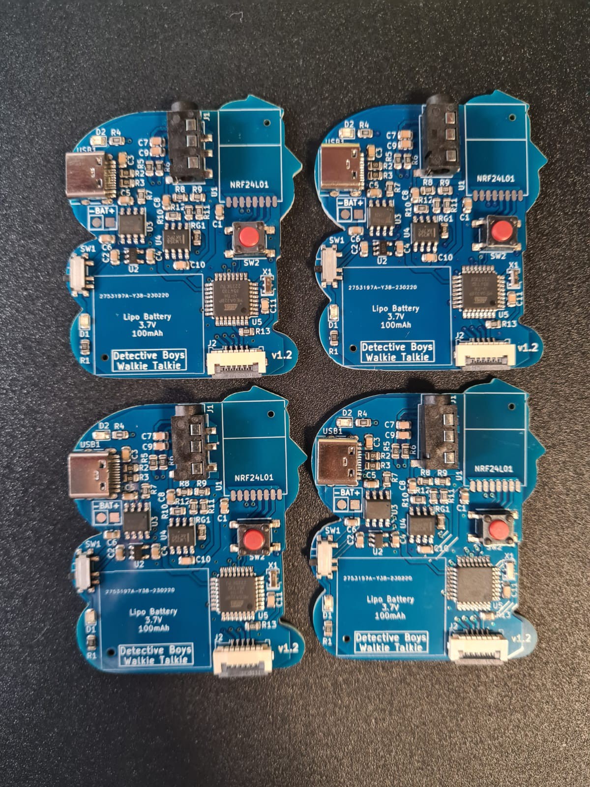
The first step is to order the main circuit board, for doing this you have two options:
The first one is to download the fabrication files from the github folder and manually order the assembled boards on any PCB manufacturer, the github page contains all necessary files for the board fabrication and assembly (gerbers, bill of materials and pick and place), I recommend ordering at JLCPCB since all the components I selected are provided from them.
The second option is to order the assembled board from PCBWay, I uploaded a project on PCBWay with all the fabrication files and board configuration already done, so you don't have to worry about it.
![]()
-
2Solder the NRF24L01 radio module
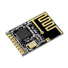
You can get the NRF24L01 modules on websites like Aliexpress or Amazon, make sure the module version is the SMD version, since this one will fit on the board footprint.
![]()
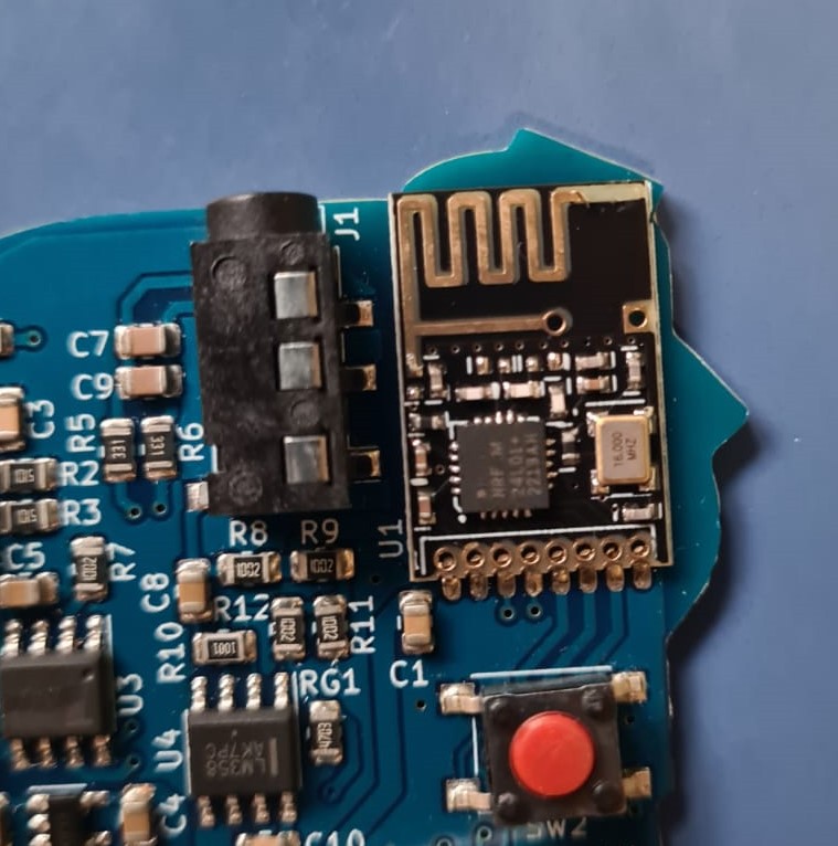
On the top right corner of the board you must solder the 8 pins of the NRF24L01 smd module, you can you preferred soldering tool, just make sure there are no solder bridges and all pads are connected afterwards.
![]()
-
3Solder the LiPo battery
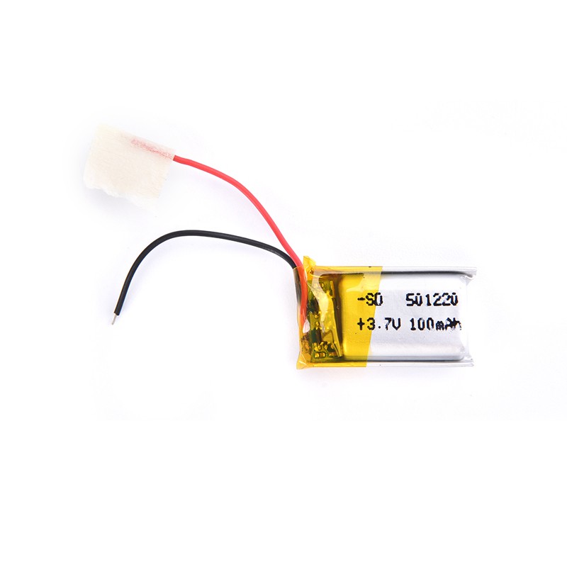
You will need a Lipo battery with 100mAh capacity, you can get a higher capacity one but take into account that more capacity means a bigger battery so it won't fit into the board, the battery must have a protection circuit included.
![]()
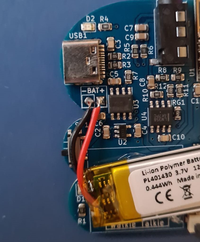
The battery must be soldered on the "BAT" connector placed below the USB charging port, I recommend using a soldering iron with an small tip, please be careful with the polarity as you could damage the whole board !
![]()
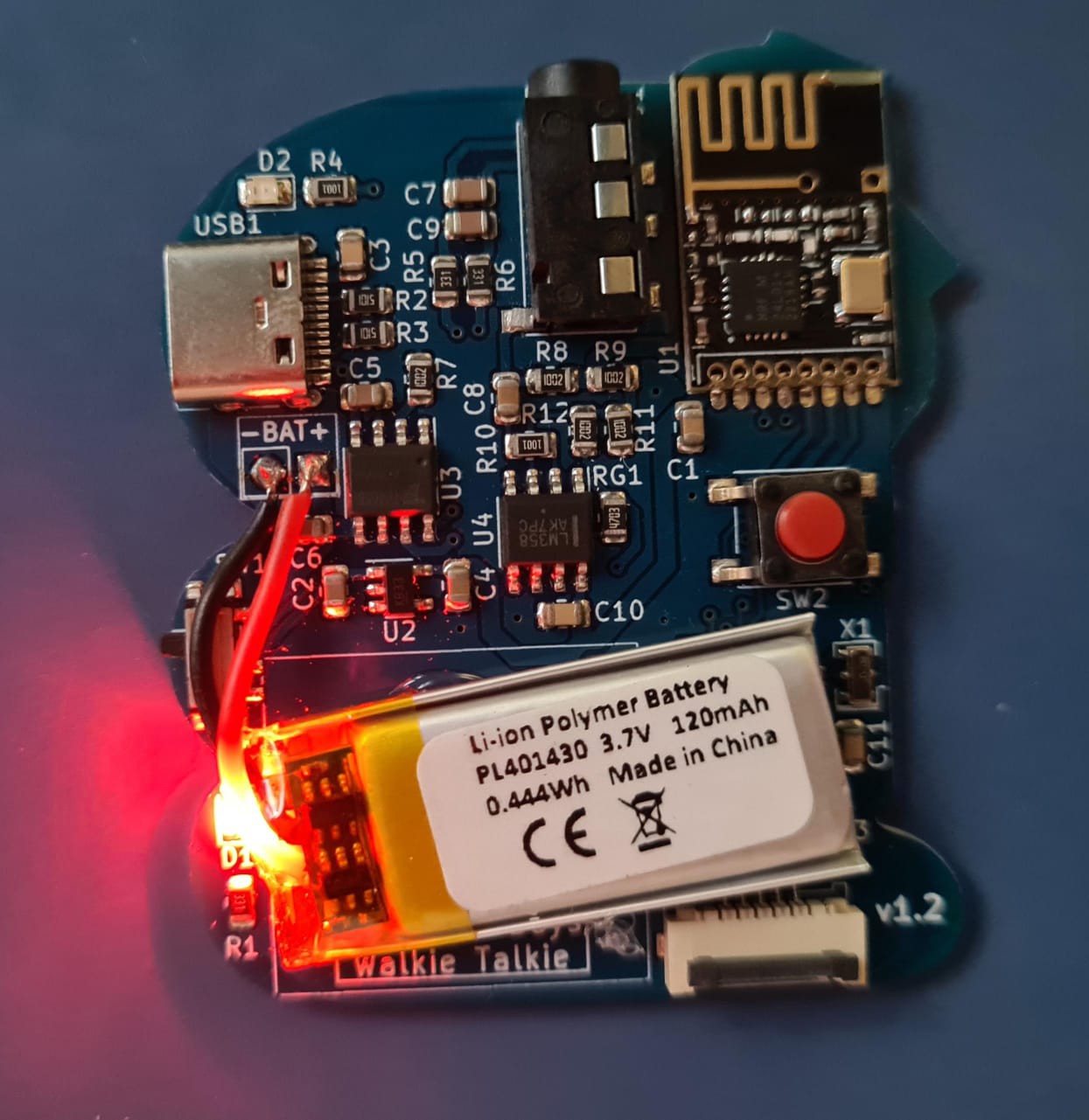
After soldering, flick the switch on the left side of the board to turn on the circuit, the red LED on the left side should light up indicating everything is OK.
![]()
-
4Program the board
You can't program the board by plugging the USB cable like a normal Arduino board, you will need an external programmer for this, luckily for you, if you don't have any AVR programmer you can use an Arduino board to work like a programmer with a few extra steps.
You can follow this short tutorial to use Arduino as ISP (program an Arduino with another Arduino), if you own an AVR programmer you can skip this step.
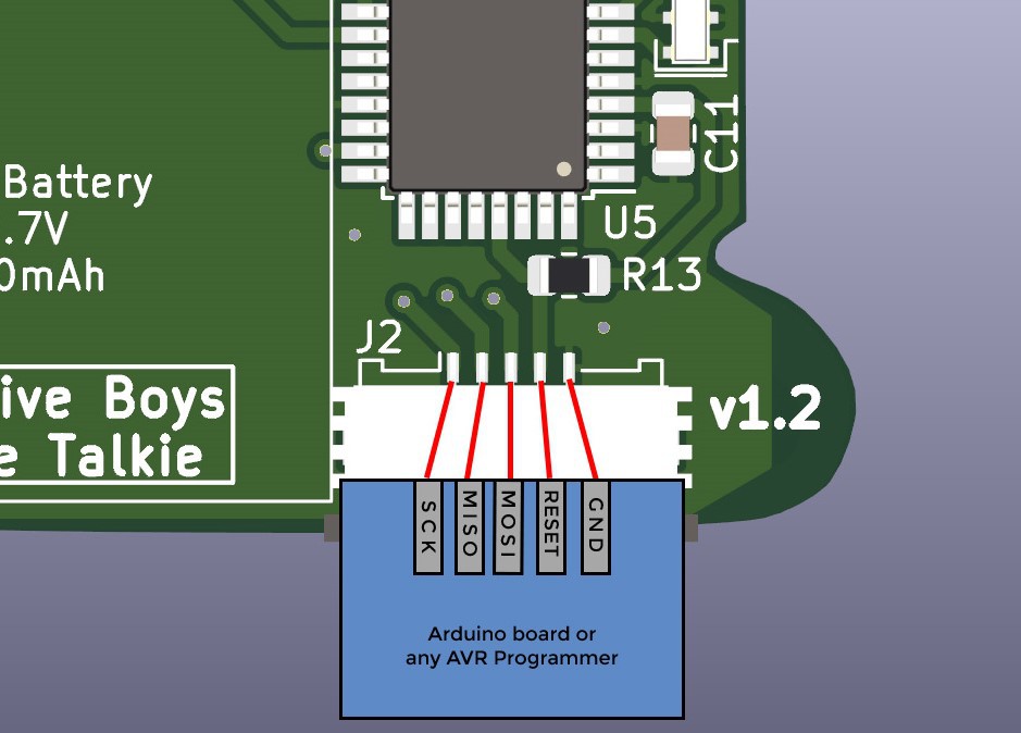
This is the wiring diagram for connecting the programming pins:
![]()
After connecting the external programmer, power the board and open the Arduino IDE and follow the next steps:
1. Choose the programmer
Tools > Programmer: "Arduino as ISP" (If you are using a different programmer select it here)
2. Burn the bootloader
Tools > Board: "Arduino Pro or Pro Mini"
Tools > Processor: "ATmega328P (3.3V, 8MHz)"
Tools > Burn Bootloader (Arduino Pro mini 3.3V 8Mhz)
3. Upload the sketch
Skecth > Upload Using Programmer
-
5Get a pair of wired headphones and test the audio
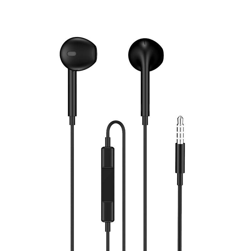
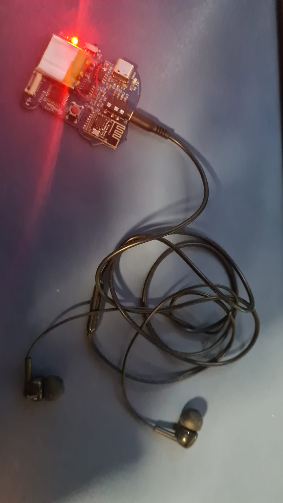
For using the walkie talkie you will need a pair of wired headphones with microphone, you can use headphones without microphone but obviously you won't be able to talk.
Headphones must have a 3.5mm jack connector, and a 32Ω impedance (which is the standard for most headphone pairs).
The microphone sensitivity will vary depending on the model, so please try different headphones and look for the one giving the best audio quality.
![]()
To test the audio, turn on the both boards and plug the headphone pairs, then press the button to transmit audio, if the audio transmission works the assembly is completed succesfully !
![]()
Detective Boys walkie talkie pin badge
Pocket-sized walkie talkie radio inspired by Detective Conan anime series using a ATMEGA328P microcontroller
 Daniel
Discussions
Become a Hackaday.io Member
Create an account to leave a comment. Already have an account? Log In.