Michael Gardi
-
A Tile Organizer
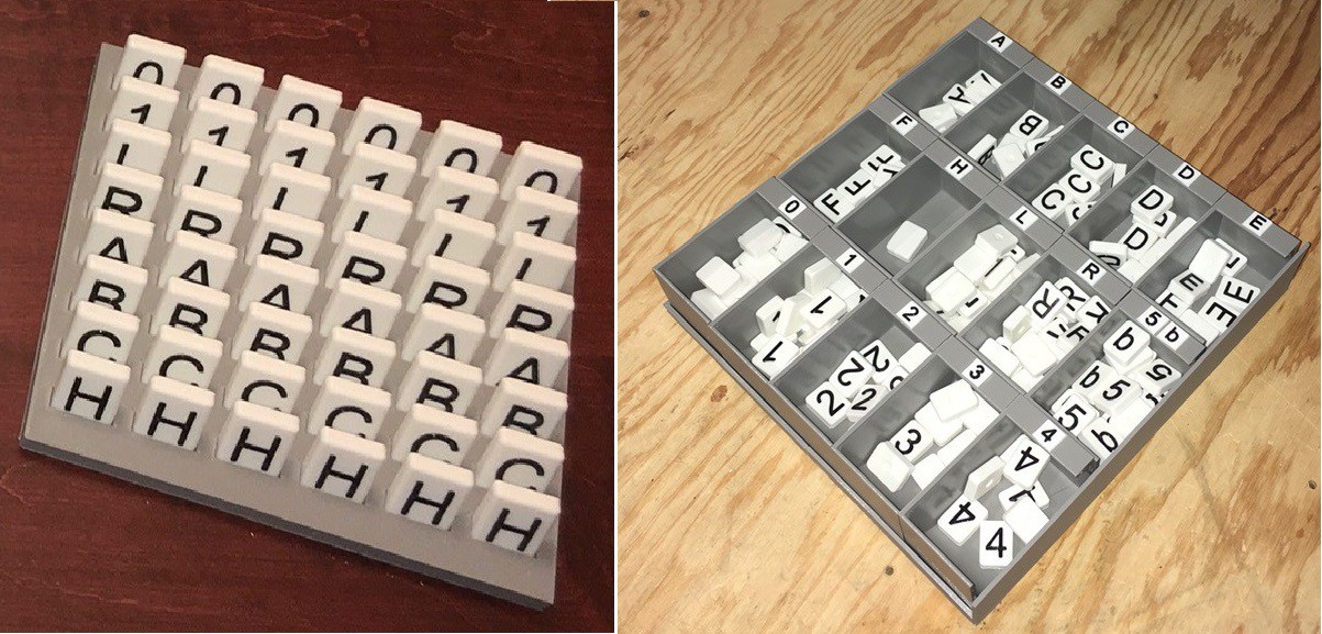
09/16/2023 at 18:16 • 0 commentsFor my first two TMD's I made bins to hold the various tiles.
![]()
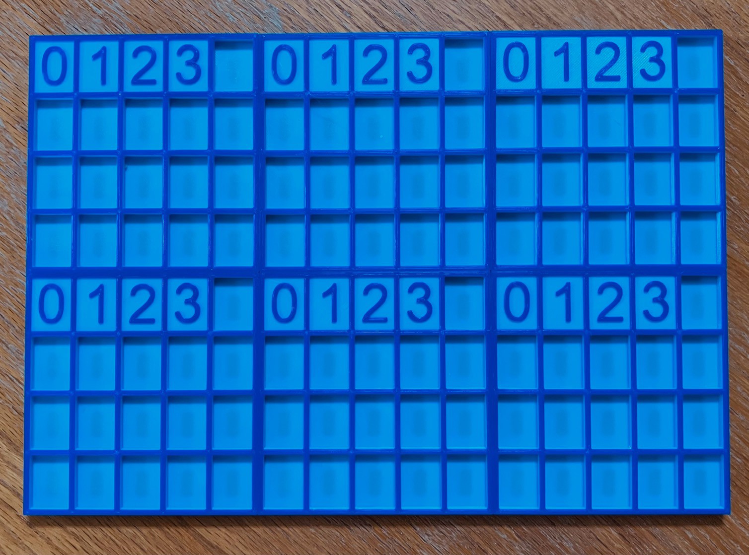
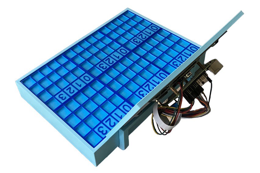
For TMD-3 I decided to take advantage of the fairly strong magnets in the tiles so I designed a grid to hold the tiles and ordered some sheet steel to mount behind the grid to attract the tiles.
![]()
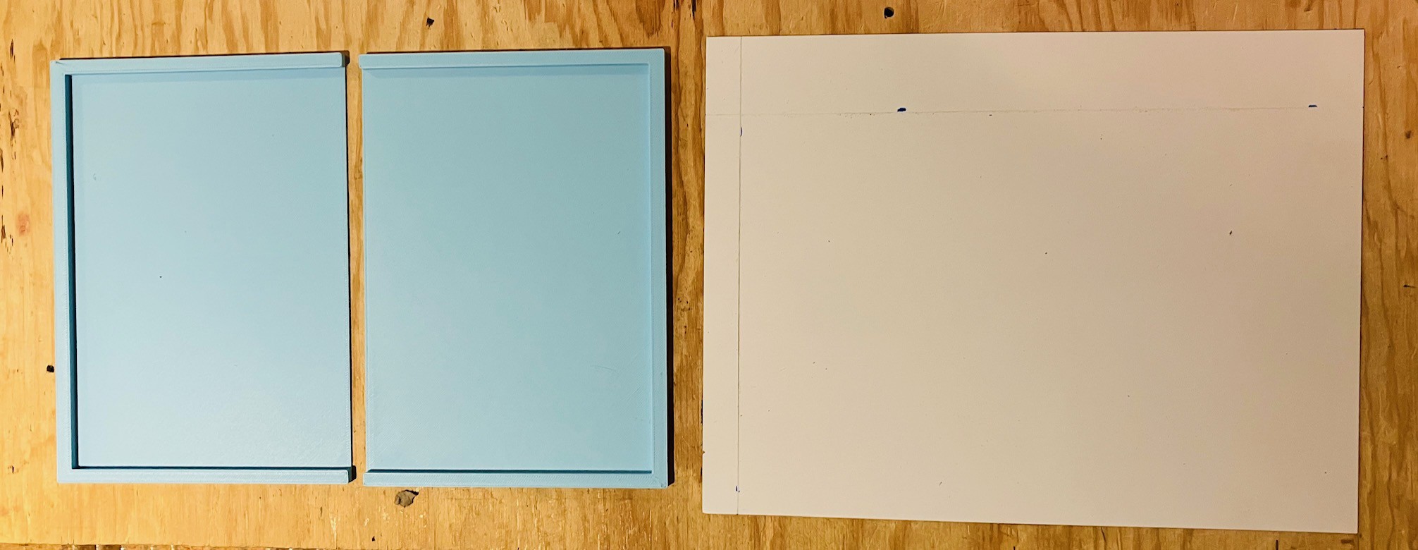
Well live and learn. I discovered that the steel I ordered was Austenitic Stainless Steel which is non-magnetic. Fortunately it was not a costly mistake and I'm sure I'll find a use for it in the future. So my plan B was to order a small cheap magnetic white board. Much better. After removing the cheap plastic frame and cardboard backing I had a nice flat magnetic backboard.
![]()
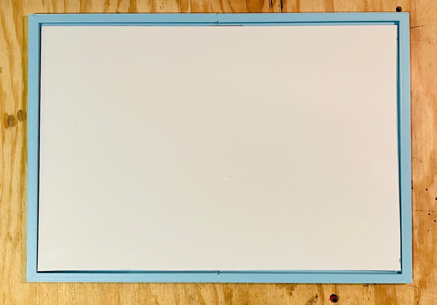
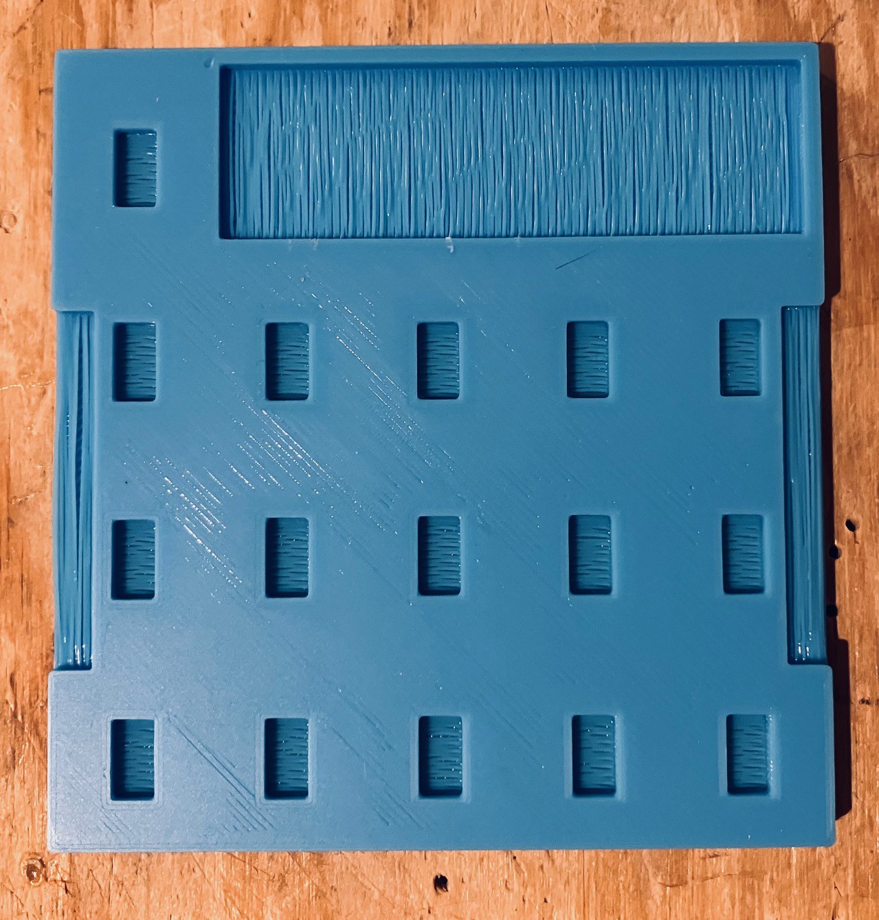
I cut the metal sheet to size and, using a CA glue, mounted it into the tile organizer frame that I printed.
![]()
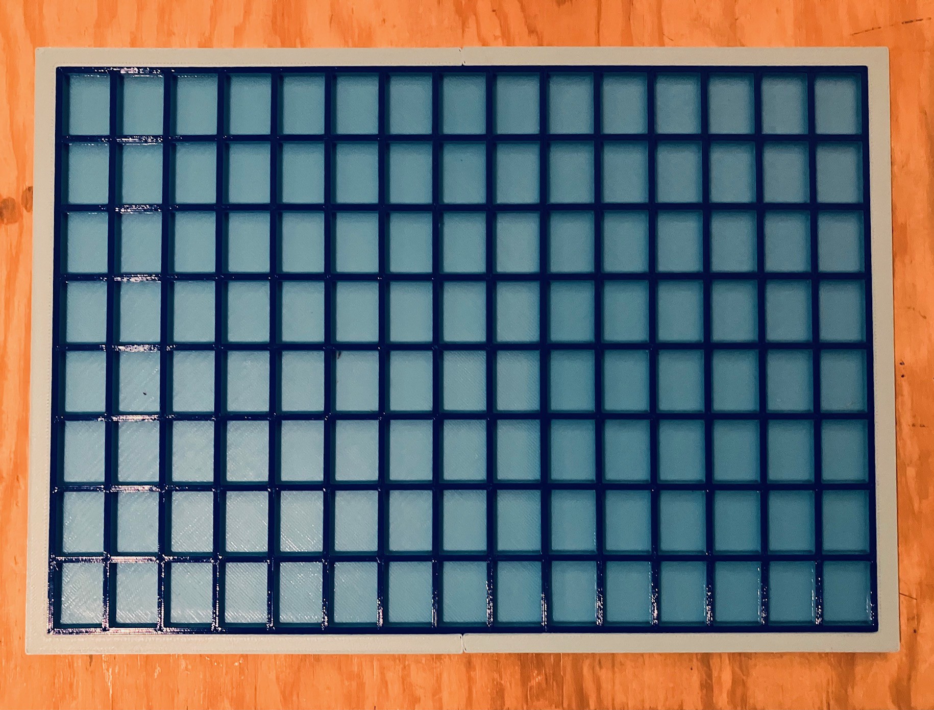
Similarly I glued in the tile organizer grid.
![]()
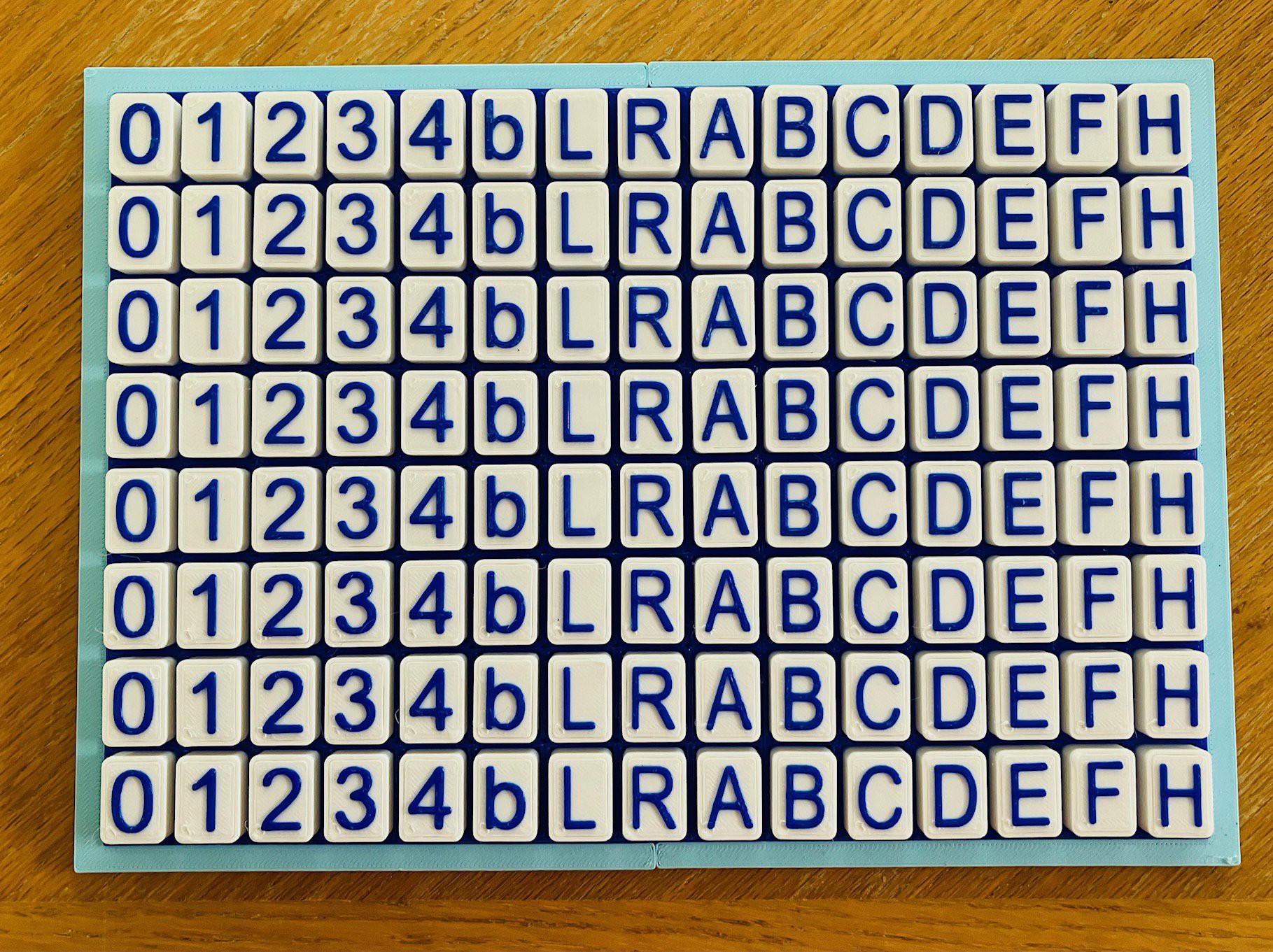
And here it is with a set of tiles installed.
![]()
The magnets hold the tiles in place nicely. You can flip the frame upside down without the tiles dislodging, yet they are easy to remove when needed. I like the coordinated look of the TMD-3 and tile organizer.
-
TMD-3 Finished
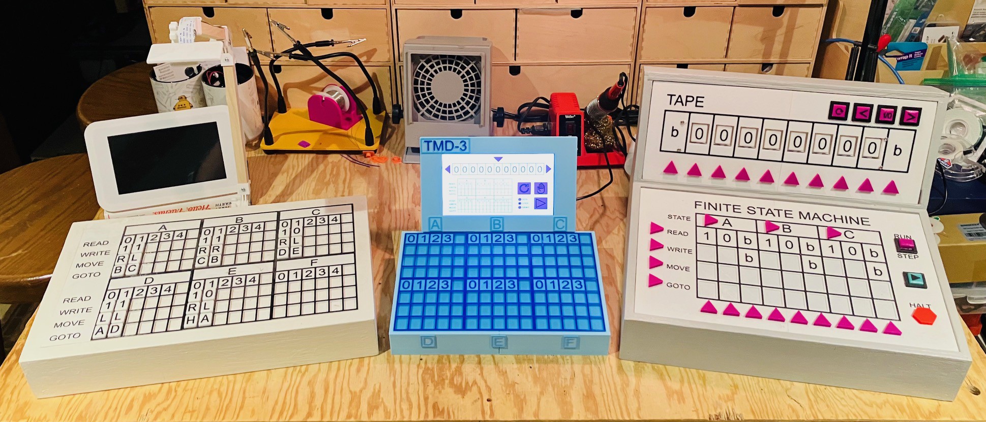
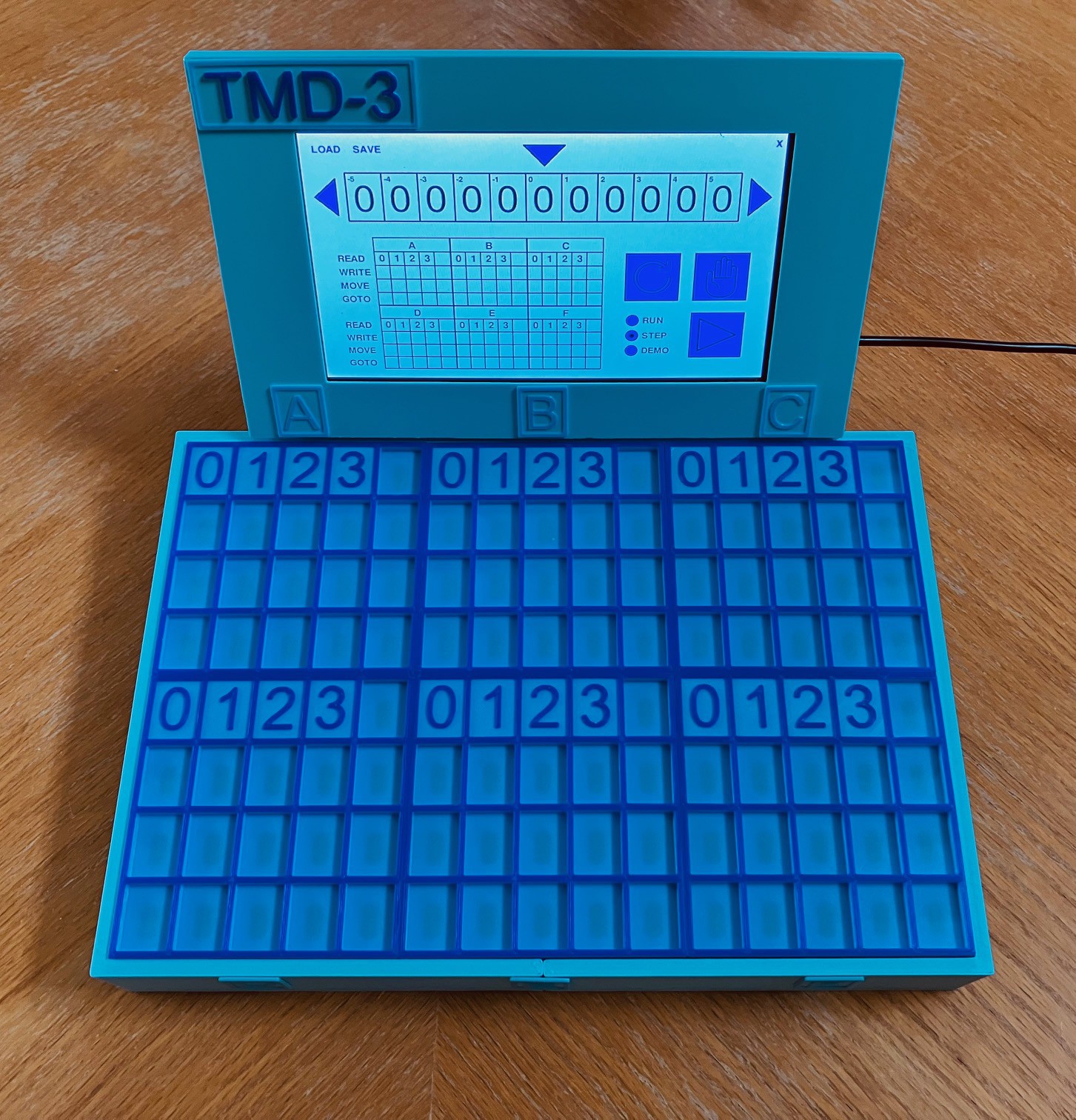
09/11/2023 at 15:44 • 0 commentsAfter playing around a bit with my TMD-3 I'm ready to say it's finished. Tiles are recognized with great accuracy which was my first goal. The end result turned out to quite compact which was something else I had hoped to achieve. Here are my three Turing Machine Demonstrators for a comparison.
![]()
One thing that I noticed is that the tiles themselves tend to lump together when loose due to the magnets that I used (6 mm). They are fine when placed into the state panels. I did not notice this with TMD-1 because the magnets that I used were smaller (3 mm) and the tiles much bigger and heavier. For TMD-2 the tiles didn't have any magnets at all. I did a quick test with 4 mm magnets and the effect was much less. I could also print the small tiles with 100% infill so they would be heavier. For now given the number of tiles I have printed and the time invested in calibration I'm not going to make the switch. In fact I plan to take advantage of the stronger magnets by creating a tile organizer backed with a steel sheet to hold the tiles in place.
-
Calibration
09/10/2023 at 18:28 • 0 commentsI finished the tedious but not too arduous task of calibrating the SS49E Linear Hall Effect Sensors. What does this mean. Well I run a small test program that I wrote that detects the presence of a tile and emits the location of the sensor and the value returned by reading that sensor. Here is the Python code.
import time
import busio
import digitalio
import board
import adafruit_mcp3xxx.mcp3008 as MCP
from adafruit_mcp3xxx.analog_in import AnalogIn
import pigpio

# Access the gpio pins.
GPIO = pigpio.pi()

# Select pins for the CD4067BE.
S0 = 23
S1 = 27
S2 = 17
S3 = 18

# Selct pins are all OUTPUT.
GPIO.set_mode(S0, pigpio.OUTPUT)
GPIO.set_mode(S1, pigpio.OUTPUT)
GPIO.set_mode(S2, pigpio.OUTPUT)
GPIO.set_mode(S3, pigpio.OUTPUT)

# Select the C8 pin.
GPIO.write(S0, 0)
GPIO.write(S1, 0)
GPIO.write(S2, 0)
GPIO.write(S3, 0)

# Create the spi bus.
spi = busio.SPI(clock=board.SCK, MISO=board.MISO, MOSI=board.MOSI)

# Create the cs (chip select).
cs = digitalio.DigitalInOut(board.D22)

# Create the mcp object.
mcp = MCP.MCP3008(spi, cs)

# Create analog input channels.
chan0 = AnalogIn(mcp, MCP.P0)
chan1 = AnalogIn(mcp, MCP.P1)
chan2 = AnalogIn(mcp, MCP.P2)
chan3 = AnalogIn(mcp, MCP.P3)
chan4 = AnalogIn(mcp, MCP.P4)
chan5 = AnalogIn(mcp, MCP.P5)

def selectPin(pin):
    if pin & 0b00000001:
        GPIO.write(S0, 1)
    else:
        GPIO.write(S0, 0)
    if pin & 0b00000010:
        GPIO.write(S1, 1)
    else:
        GPIO.write(S1, 0)
    if pin & 0b00000100:
        GPIO.write(S2, 1)
    else:
        GPIO.write(S2, 0)
    if pin & 0b00001000:
        GPIO.write(S3, 1)
    else:
        GPIO.write(S3, 0)

# The hall effect sensor will read in the middle of the range
# someplace. Get the middle values for all 16 sensors.
mids0 = []
mids1 = []
mids2 = []
mids3 = []
mids4 = []
mids5 = []
for i in range(0,16):
    selectPin(i)
    time.sleep(0.01)
    mids0.append(chan0.value)
    mids1.append(chan1.value)
    mids2.append(chan2.value)
    mids3.append(chan3.value)
    mids4.append(chan4.value)
    mids5.append(chan5.value)
print(mids0)
print(mids1)
print(mids2)
print(mids3)
print(mids4)
print(mids5)

while True:

    for i in range(0,16):
        selectPin(i)
        time.sleep(0.01)
        val = chan0.value-mids0[i]
        if abs(val) > 200:
            print("C",i,"=",round(val/10))
        val = chan1.value-mids1[i]
        if abs(val) > 200:
            print("B",i,"=",round(val/10))
        val = chan2.value-mids2[i]
        if abs(val) > 200:
            print("A",i,"=",round(val/10))
        val = chan3.value-mids3[i]
        if abs(val) > 200:
            print("D",i,"=",round(val/10))
        val = chan4.value-mids4[i]
        if abs(val) > 200:
            print("E",i,"=",round(val/10))
        val = chan5.value-mids5[i]
        if abs(val) > 200:
            print("F",i,"=",round(val/10))

    time.sleep(0.5)
So for each of the 96 sensors I get the values for only those tiles that are valid for that position. So for instance the MOVE row only accepts L and R tiles. By only accepting valid row tiles there is some error checking, but because there are only 8 different magnet configurations, some tiles are interchangeable like the 2 and E tiles for instance. I add those values to a table specific to the state being checked. Here is the table for the C state.
    # Add the valid tiles to each sensor along with the expected sensor value.
    # C

    # READ Row
    sensors[0][8]["tiles"] = [(-627,'b'), (282,'4')]

    # WRITE Row
    sensors[0][4]["tiles"] = [(-435,'0'), (-301,'1'), (691,'2'), (429,'3'), (301,'4')]
    sensors[0][5]["tiles"] = [(-410,'0'), (-282,'1'), (640,'2'), (397,'3'), (275,'4')]
    sensors[0][6]["tiles"] = [(-384,'0'), (-262,'1'), (589,'2'), (365,'3'), (262,'4')]
    sensors[0][7]["tiles"] = [(-371,'0'), (-256,'1'), (576,'2'), (358,'3'), (256,'4')]
    sensors[0][9]["tiles"] = [(-358,'0'), (-250,'1'), (563,'2'), (352,'3'), (250,'4')]

    # MOVE Row
    sensors[0][0]["tiles"] = [(-205,'L'), (205,'R')]
    sensors[0][1]["tiles"] = [(-192,'L'), (192,'R')]
    sensors[0][2]["tiles"] = [(-179,'L'), (179,'R')]
    sensors[0][3]["tiles"] = [(-179,'L'), (179,'R')]
    sensors[0][10]["tiles"] = [(-173,'L'), (173,'R')]

    # GOTO Row
    sensors[0][12]["tiles"] = [(-749,'A'), (-474,'B'), (-307,'C'), (-218,'D'), (723,'E'), (467,'F'), (320,'H')]
    sensors[0][13]["tiles"] = [(-653,'A'), (-422,'B'), (-275,'C'), (-198,'D'), (627,'E'), (410,'F'), (282,'H')]
    sensors[0][14]["tiles"] = [(-608,'A'), (-390,'B'), (-262,'C'), (-186,'D'), (595,'E'), (384,'F'), (269,'H')]
    sensors[0][15]["tiles"] = [(-602,'A'), (-384,'B'), (-250,'C'), (-179,'D'), (570,'E'), (384,'F'), (269,'H')]
    sensors[0][11]["tiles"] = [(-602,'A'), (-384,'B'), (-256,'C'), (-186,'D'), (557,'E'), (378,'F'), (256,'H')]
There will be one of these tables for each of the six states.
You might ask why is calibration necessary for all six states? Well for sure you have to calibrate at least one state in the table to get the initial sensor readings for the tiles. Once I had the values for my first state I tried using those reading for all of the other states as well. You know they worked pretty good but not perfectly. Despite my best efforts to be as consistent as possible, there is enough variance between different sensor readings that a some tiles could not be recognized or were incorrect. Why the variance? Well the sensors themselves while carefully soldered to the PCB would not be perfectly aligned. The printed state panels when joined probably have some slight differences in height from the sensors. You get the idea.
With all six state panels calibrated the recognition fidelity is great.
-
Final Assembly
09/09/2023 at 19:18 • 0 commentsI attached the wired State Panels to the console frame using some two sided tape. Notice here that I have added a logo and some labels for the state panels.
![]()
Then I connected the bottom and top row panels with the cable I made and plugged in the cable from the Pi 4.
![]()
Finally I glued the six State Panels together to create a more stable connection between the PCBs and printed panels.
![]()
When the glue dried I placed the joined panels into the console. Nice clean fit with no jiggle. Just what I was looking for.
![]()
All that's left now is to calibrate the 96 sensors against this final configuration.
-
Finished Wiring
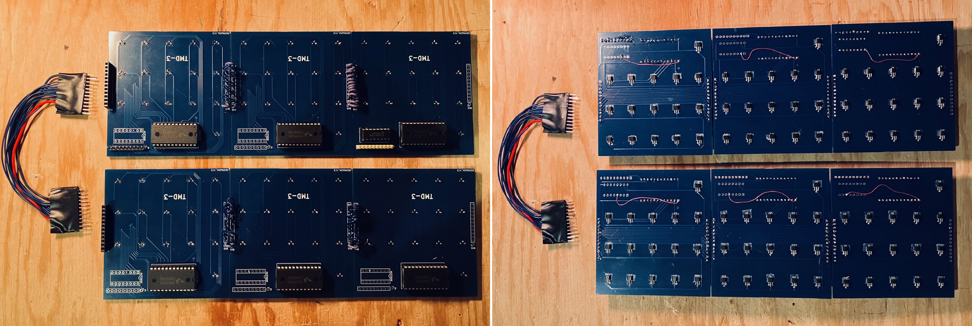
09/07/2023 at 21:08 • 0 commentsWell after installing 96 SS49E Linear Hall Effect Sensors, 6 16-channel Analog Multiplexers, 1 8-channel 10-bit A/D converter chip, and 72 wires to connect the 6 State Panels, the wiring is done.
![]()
To make installation into the chassis easier I have made a cable and added headers to join the top and bottom rows of the state table.
After connecting the first two State Panels together I realized that the 12 short 22 AWG wires were too "stiff" which made aligning the two joined panels harder than it should have been. So for subsequent joins I used 22 AWG for the two outside joins. and used 28 AWG wire for all the rest. Much better.
-
More Console Work
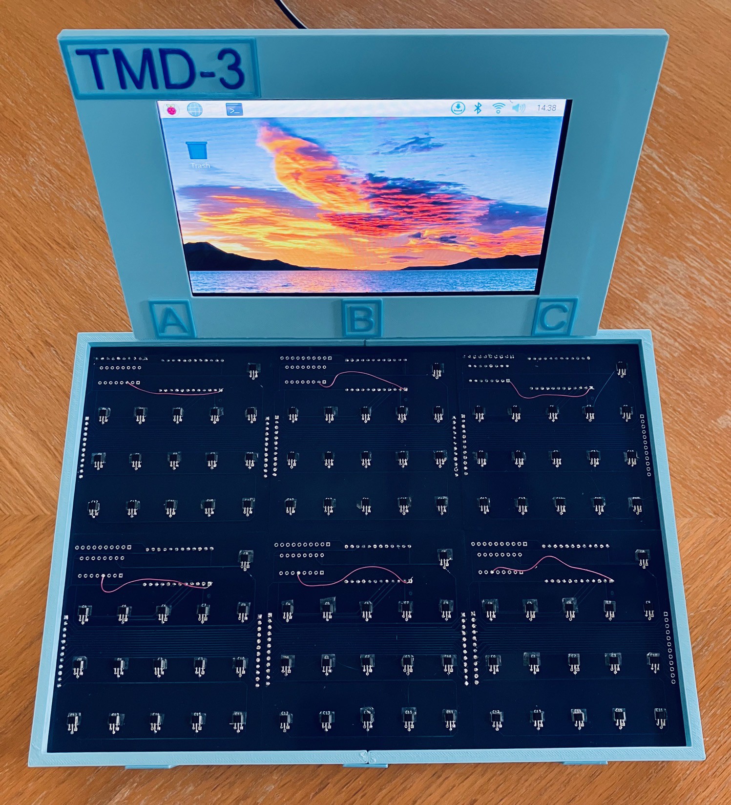
09/02/2023 at 13:59 • 0 commentsI reworked the frame for the 7" Raspberry Pi Touch Display and integrated it into the existing console.
![]()
![]()
Just four more panel PCB to populate as I approach the finishing line.
-
Two Panels Now Working
08/30/2023 at 19:25 • 0 commentsSo I got the second panel integrated into the Console application.
![]()
I'm pretty happy with the way that everything is working out and now have the confidence to proceed with the additional four panels.
One thing that I have learned is that there is enough variance between the sensors to warrant taking the time to calibrate each sensor against the tiles that are expected to be placed in that position of the State Panel. I'm sure that despite my best efforts to position each sensor in the precise same position that readings are bound to differ. Calibrating the sensors helps to mitigate the slight difference I am finding between tiles of the same value. Here is what that calibration looks like in my code (so far).
# Sensors connected to channel 0 of the MCP3008 8-channel A/D converter.
# READ row.
sensors[0][8]["tiles"] = [(-621,'b'), (275,'4')]

# WRITE row
sensors[0][4]["tiles"] = [(-493,'0'), (-339,'1'), (768,'2'), (474,'3'), (339,'4')]
sensors[0][5]["tiles"] = [(-454,'0'), (-301,'1'), (678,'2'), (429,'3'), (307,'4')]
sensors[0][6]["tiles"] = [(-403,'0'), (-282,'1'), (627,'2'), (390,'3'), (282,'4')]
sensors[0][7]["tiles"] = [(-397,'0'), (-275,'1'), (614,'2'), (384,'3'), (282,'4')]
sensors[0][9]["tiles"] = [(-390,'0'), (-275,'1'), (589,'2'), (371,'3'), (266,'4')]

# GOTO row
sensors[0][0]["tiles"] = [(-230,'L'), (237,'R')]
sensors[0][1]["tiles"] = [(-218,'L'), (224,'R')]
sensors[0][2]["tiles"] = [(-205,'L'), (205,'R')]
sensors[0][3]["tiles"] = [(-198,'L'), (205,'R')]
sensors[0][10]["tiles"] = [(-198,'L'), (198,'R')]

# MOVE row.
sensors[0][12]["tiles"] = [(-877,'A'), (-563,'B'), (-358,'C'), (-256,'D'), (890,'E'), (576,'F'), (371,'H')]
sensors[0][13]["tiles"] = [(-787,'A'), (-506,'B'), (-320,'C'), (-224,'D'), (794,'E'), (518,'F'), (339,'H')]
sensors[0][14]["tiles"] = [(-749,'A'), (-486,'B'), (-307,'C'), (-224,'D'), (762,'E'), (493,'F'), (320,'H')]
sensors[0][15]["tiles"] = [(-762,'A'), (-480,'B'), (-314,'C'), (-224,'D'), (755,'E'), (493,'F'), (320,'H')]
sensors[0][11]["tiles"] = [(-749,'A'), (-474,'B'), (-307,'C'), (-218,'D'), (742,'E'), (480,'F'), (314,'H')]
If you look at the columns for each row and tile you can see a variance of as much as 100 in some cases.
Another thing that I want to look at is to somehow attach the printed panel to the PCB so that the calibration doesn't change. (Two sided tape maybe?) Right now the panels are just resting on the PCBs.
-
Starting to Put Together the Console
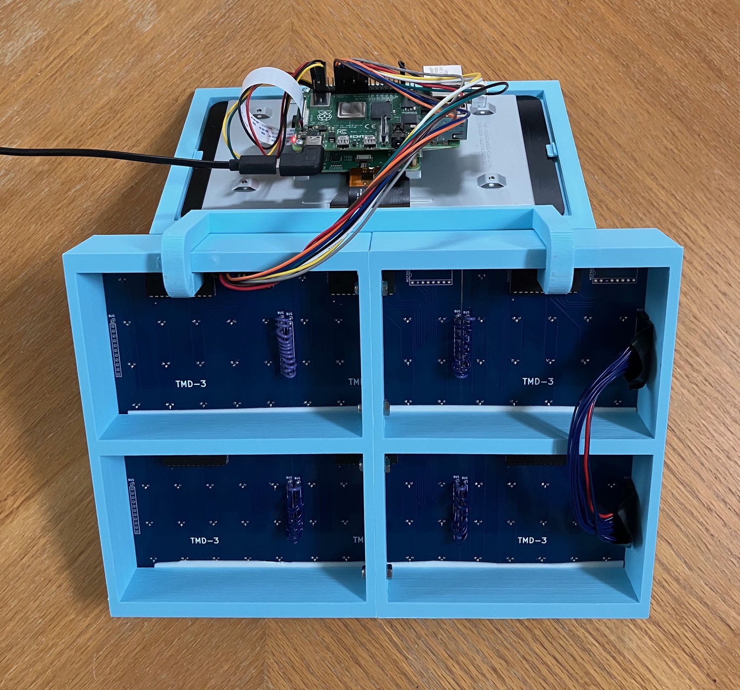
08/29/2023 at 14:58 • 0 commentsI populated a second State Panel PCB with the Linear Hall Effect Sensors and a CD4067BE multiplexer. Only the first panel needs to have a MCP3008 8-channel A/D converter. I then connected the two panels together via the bus pins with some AWG22 solid core wire.
![]()
I designed and printed a frame to hold all six State Panels.
![]()
Notice that the second (leftmost) panel is wired to Channel 1 of the MCP3008 on the first panel (via the bus).
One more change, I increased the size of the cutouts on the bottom of the printed panel so that the panel and the PCB now lie flush.
![]()
-
Demonstration of the State PCB
08/23/2023 at 15:00 • 0 commentsHere is a short video of the State PCB in action.
I also posted the KiCad files I used to produce the PCB to GitHub.
-
Setting Up the Pi
08/21/2023 at 18:49 • 0 commentsUp until now I have been running all my tests on the Raspberry Pi that I used for my TMD-2 project. I'm moving to a new Pi so I though I would document the steps I have taken to get the Console running on the new image.
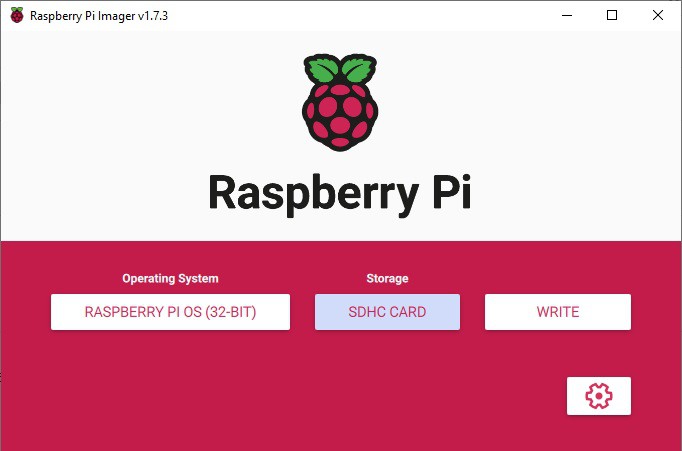
I'm not going to detail getting the Raspberry Pi OS onto the Pi 4 as there are a lot of guides out there like this one from tom'sHARDWARE. Basically I just loaded a Raspberry Pi OS image onto a 32G microSD card using Raspberry Pi Imager.
![]()
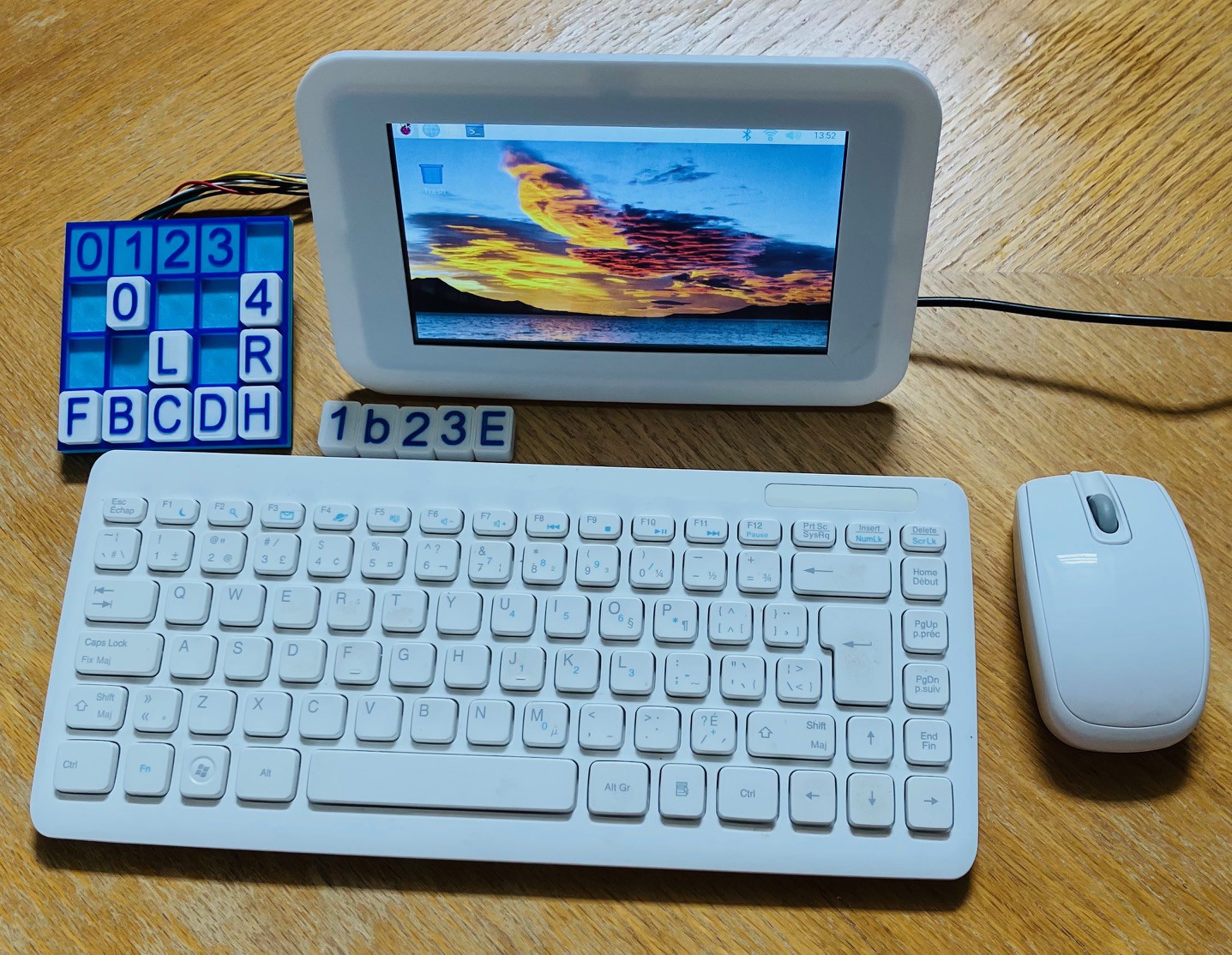
I plugged the microSD card with the brand new OS image into the Pi 4 I have been using for testing with it's small LCD screen, wireless mouse, and keyboard. You could do the installation completely "headless" as outlined here, but I prefer to do the configuration interactively with this setup. I powered up the Pi and went through the initial configuration dialogs to set the login user, keyboard, language, locale, and wireless connection. Super easy.
![]()
Ultimately the Pi could be running headless with no keyboard or mouse. There will however be a display to show the console's screen. My preference is to use VNC to accomplish this. Raspberry Pi OS ships with RealVNC pre-installed. So the first thing that I did after the basic OS had been installed was to setup a virtual server for the RealVNC client to connect to. The easiest way I have found to do this is to add the following lines to the end of the /etc/rc.local file before the exit 0 on the Pi.
# Setup a virtual screen for the VNC server.
sudo -u xxxxxx vncserver-virtual -randr=1920x1080

# Start the Pi GPIO daemon.
sudo pigpiod
xxxxx is the login user that you setup to access the Raspberry Pi. Set the screen dimension (randr=) to be the same as the machine that you will be accessing the TMD-3 Console from.
At the same time that I added the virtual VNC server I added the "sudo pigpiod" line to start a daemon that the console needs to access the Pi's GPIO pins.
I found in my setup that there were a few issues accessing this server with the RealVNC client on my Windows machine. The first was that the menu bar at the top of the desktop was missing. If you encounter this issue, to restore the desktop menu bar enter the following command.
sudo apt-get remove --purge alsa-base pulseaudio
On a similar note the title bar on open application windows and the corresponding windows controls (v ^ x) were missing as well. To fix this I edited the desktop.conf file,
sudo nano /etc/xdg/lxsession/LXDE-pi/desktop.conf
and changed the line:
window_manager=mutter to window_manager=openbox-lxde-pi
then saved the changes.
An additional library is required by the Console to interact with the MCP3008 ADC chip used to "read" the Hall Effect sensors. To load the library:
sudo pip3 install adafruit-circuitpython-mcp3xxxWith these changes made reboot the Pi 4 for them to take effect.
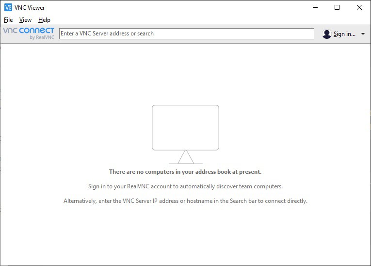
I downloaded and installed the RealVNC client on my Windows machine. Run the RealVNC VNC Viewer. You should see this window.
![]()
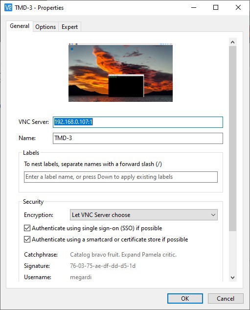
From the menu select File->New connection... to bring up the following dialog. Add the Server address and common name then click OK.
![]()
Note the :1 added to the server address. This references the instance of the VCN Server running.
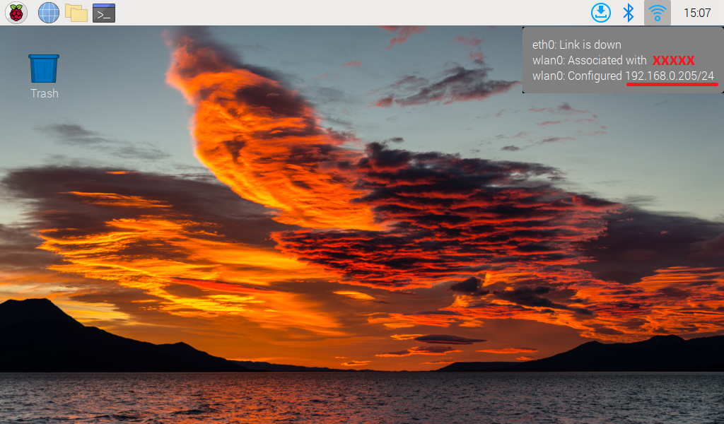
To find the VNC Server address you can just hover over the WiFi (or network) connection on the server desktop.
![]()
From the main VNC Viewer window double click on the TMD-3 connection just created.
![]()
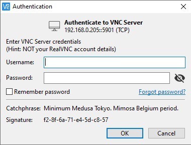
The first time you attempt a connection you will be prompted to enter the Raspberry Pi's login credentials. Check Remember password if you don't want to have to do this every time you connect. Enter the credentials and click OK.
![]()
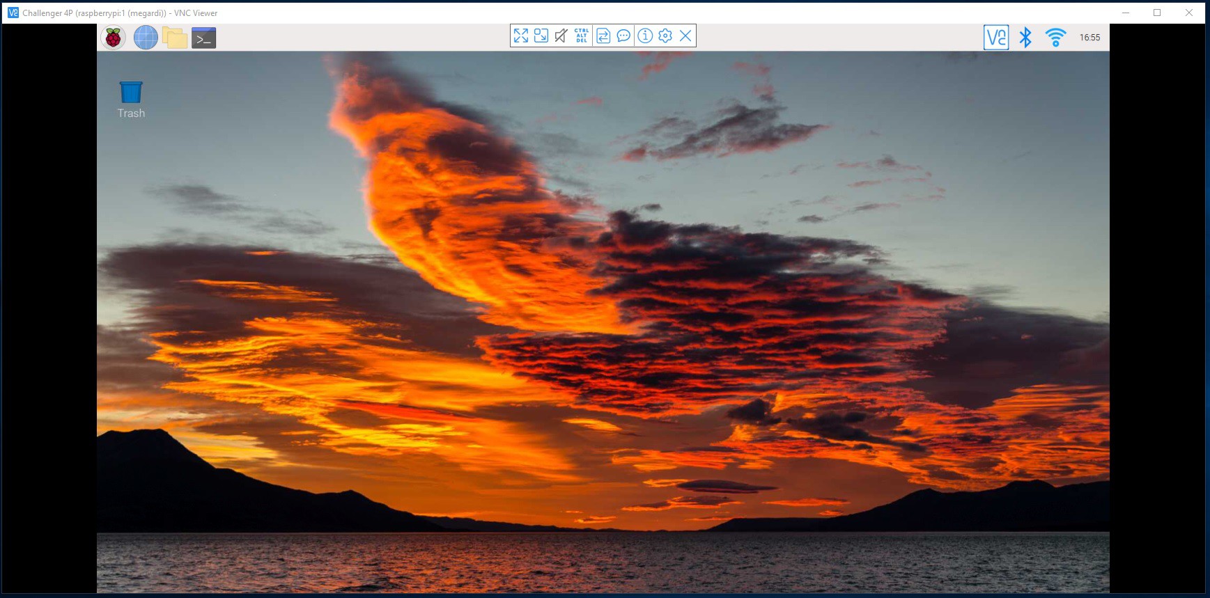
You should see an instance of the Pi 4's desktop.
![]()
Be To get the Console onto the Pi 4 you can simply clone the repository from github. Open a terminal window and enter the following command:
git clone https://github.com/kidmirage/Turing-Machine-Demonstrator-Mark-3-
To run the Console execute the following commands:
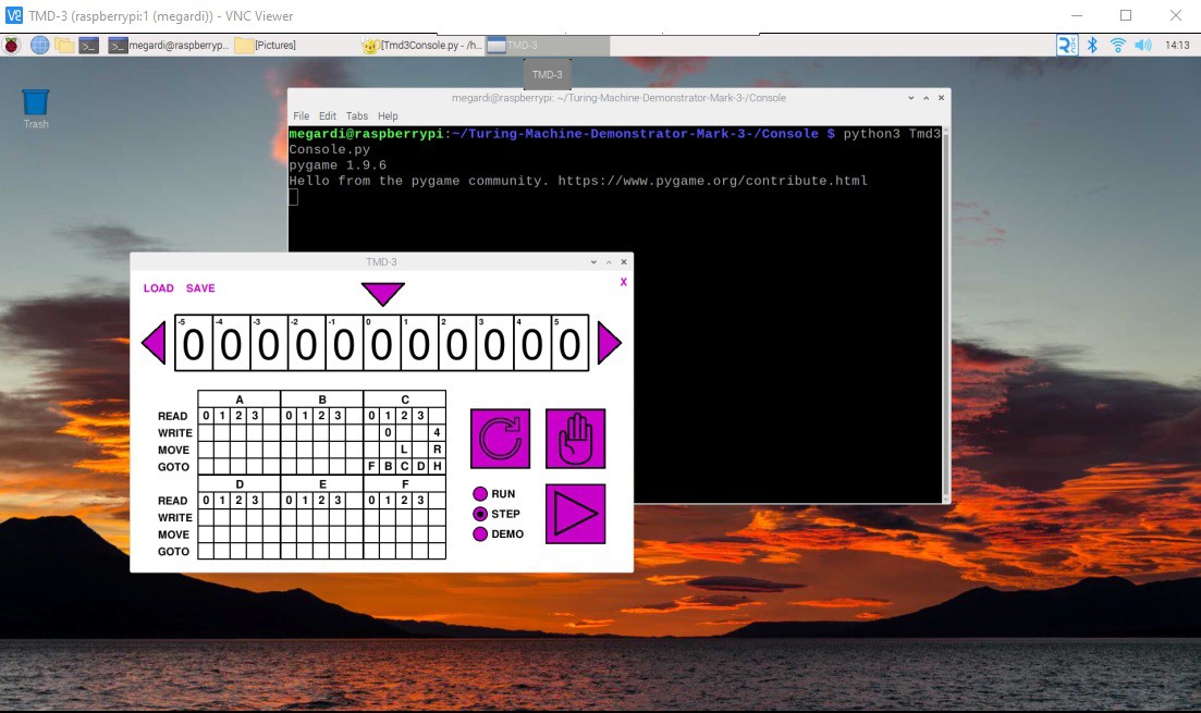
cd Turing-Machine-Demonstrator-Mark-3-/Console
python3 Tmd3Console.py
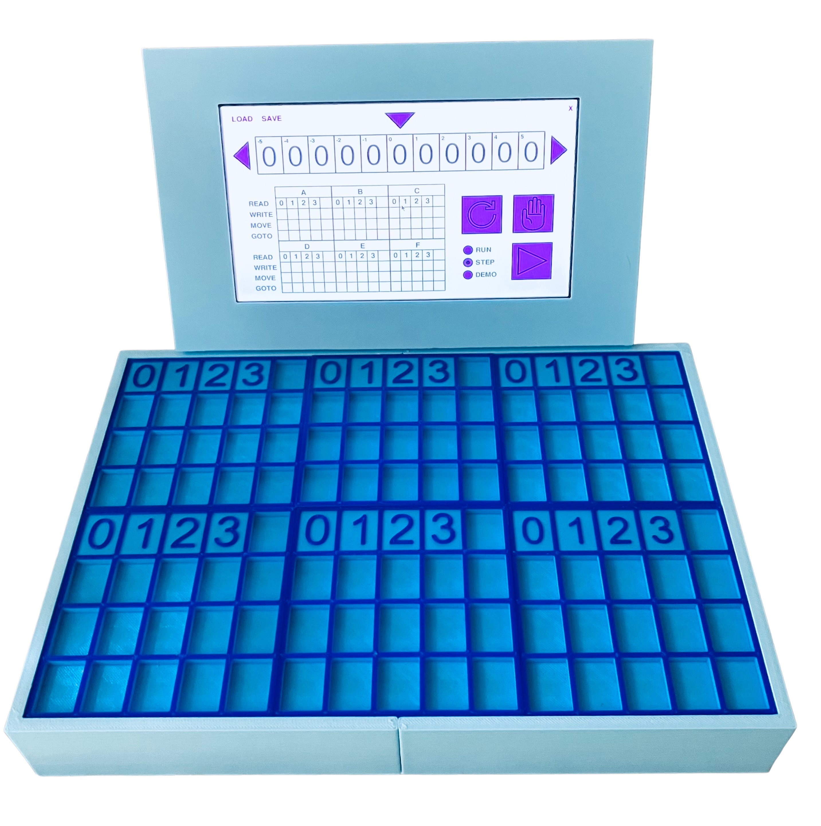
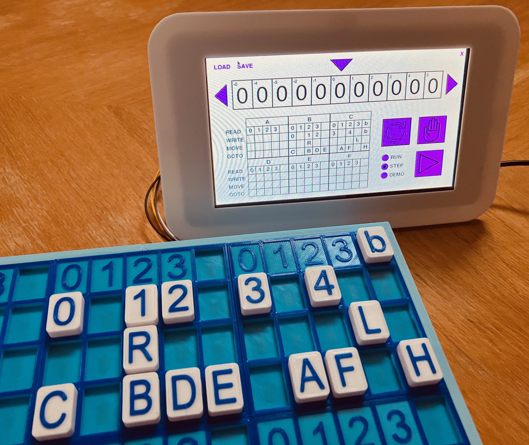
You should see the TMD-3 Console popup.
![]()
Autostart
One of the finishing touches I wanted on this project is to make the Raspberry Pi boot directly into the TMD-3 Console on startup.
I created an autostart folder on my Pi and switched to that folder. The xxxxxx is the username that you logged in as.
mkdir /home/xxxxxx/.config/autostart
cd /home/xxxxxx/.config/autostart
Into the autostart folder just created I added the following two files.
runTMD-3
cd /home/xxxxxx/Turing-Machine-Demonstrator-Mark-3-/Console
/usr/bin/python3 Tmd3Console.py
TMD-3.desktop
[Desktop Entry]
Type=Application Name=TMD-3
Exec=/home/xxxxxx/.config/autostart/runTMD-3
In addition the runTMD-3 file must be made executable with the following command:
sudo chmod 777 runTMD-3
Now if you reboot the system, you should briefly see the desktop appear, and shortly after the TMD-3 Console will load.
TMD-3: Turing Machine Demonstrator Mark 3
They say that the third time's a charm. Let's find out.