 Simen Sollihøgda
-
1Overview
- Order pcb
- Order non jlcpcb parts
- Turn the binding posts
- Solder on parts
- 3dPrint enclusure
- uploading software
- Assembely
-
2Order pcb from JLCPCB
Download gerber, cpl and bom files to your computer
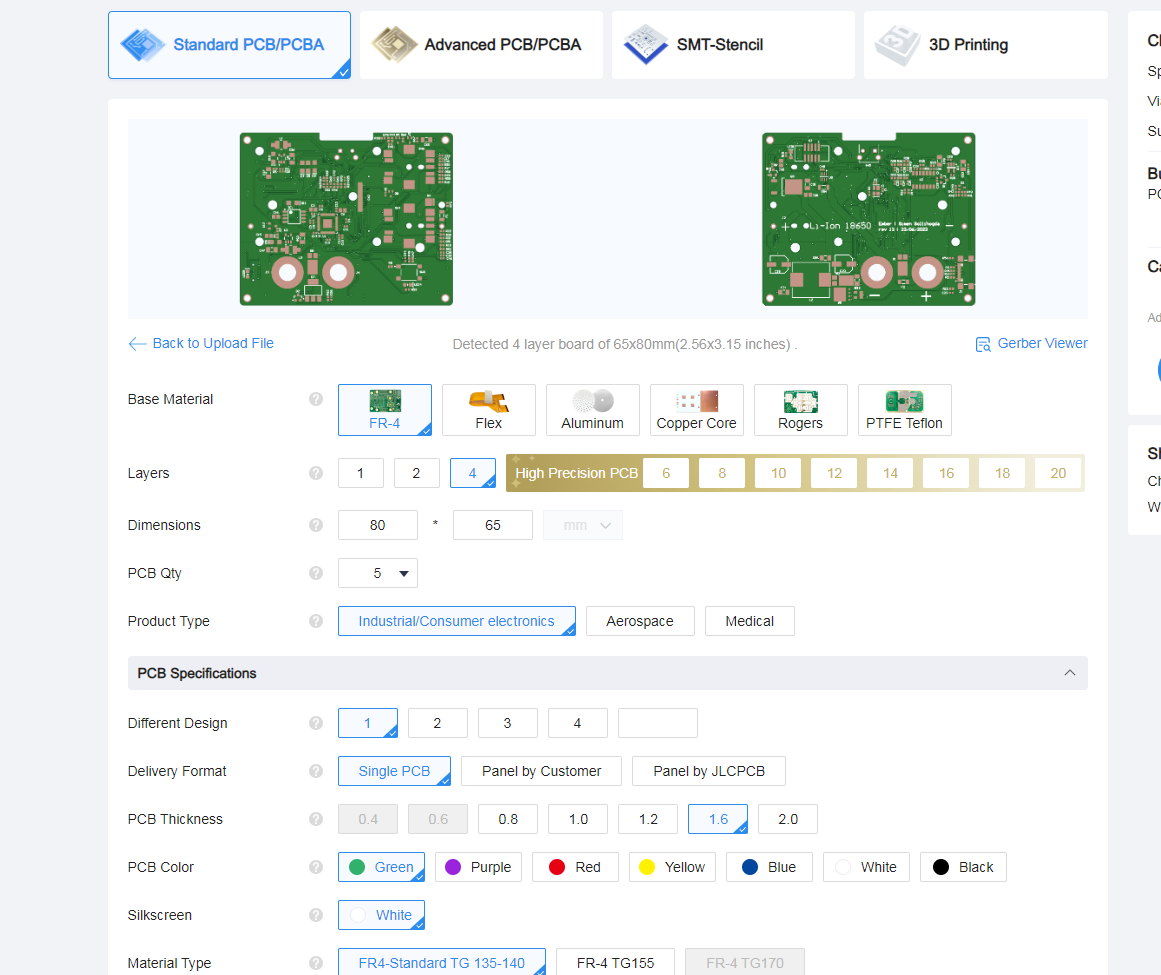
go to Jlcpcb.com and select PCB Assembly
upload gerber file
The Dimentions should automaticly update to 80 x 65 and number of layers to 4. leave all other choices as default.
![]()
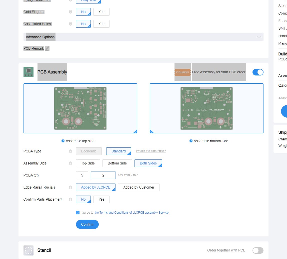
Enable PCB assembely and select standard and both sides.
![]()
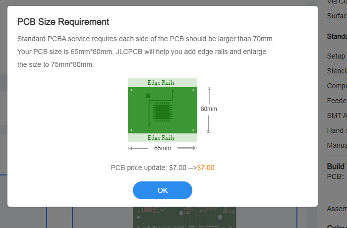
When asked about PCB Size Requirment click OK
![]()
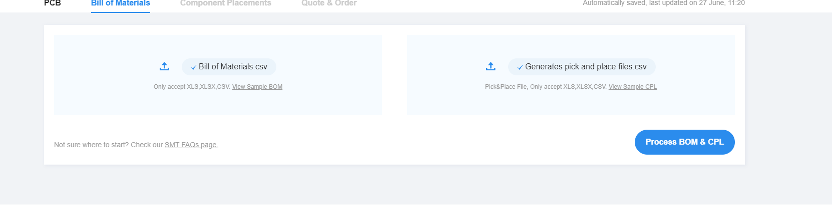
Then you will be asked to upload bom and clp files, do so
![]()
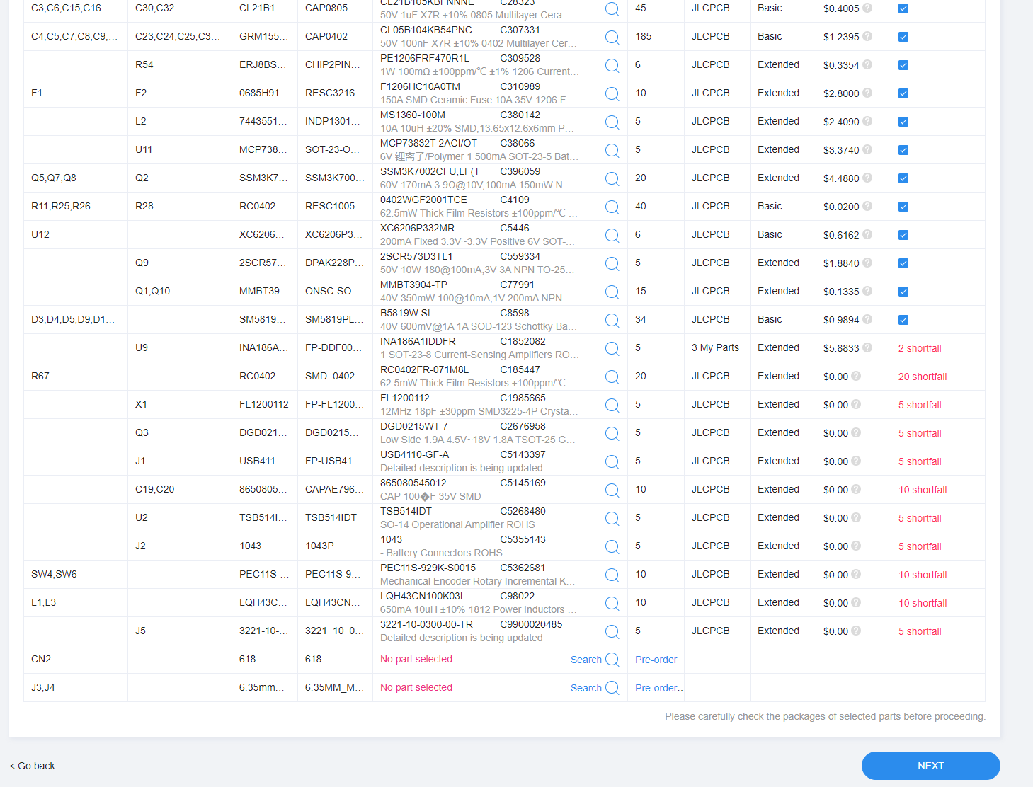
You will then get a list of all parts in the project that are going to be assembled.
There may be some parts that is out of stock. What I have done in that case is that I have ordered the missing parts from Digikey.com and soldered them on manually.
The 618 part is the display, and I always solder them manually. That's also the case with the 6.35mm_mounting_hole witch is where the binding posts will be attached.
To reduce cost of the assembly I also leave the 1043 battery connector unassembled at do that by hand later.
![]()
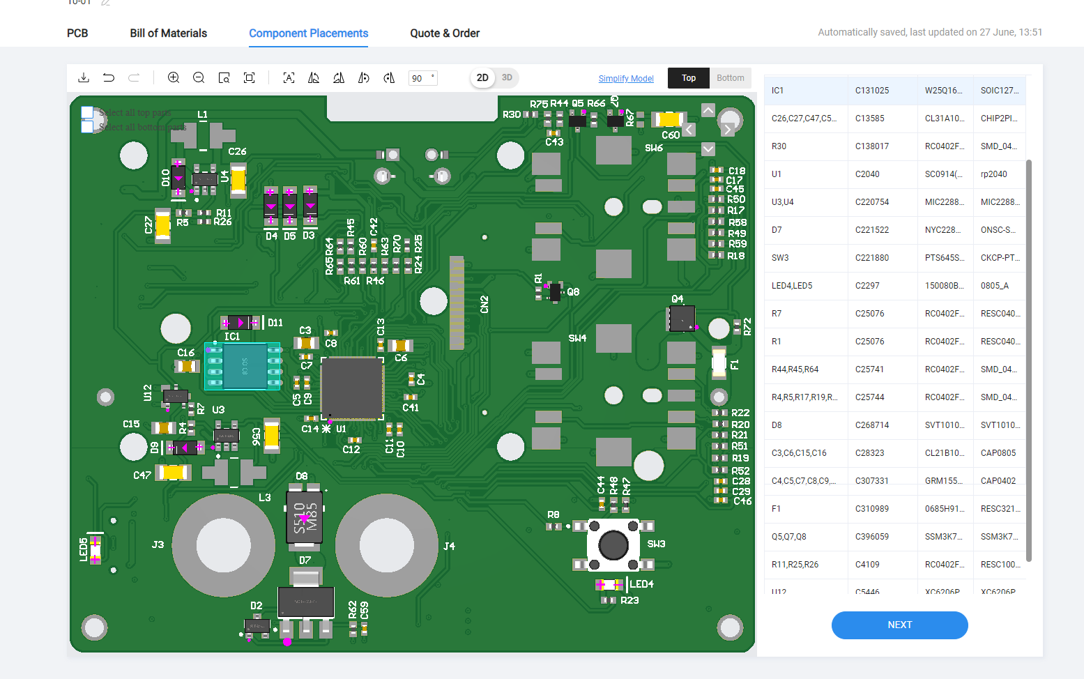
Next is component placements. It could be fine to leave this as is, but take a look to see that it looks like all the parts are in the right place.
The components that is missing is the components that was out of stock.
![]()
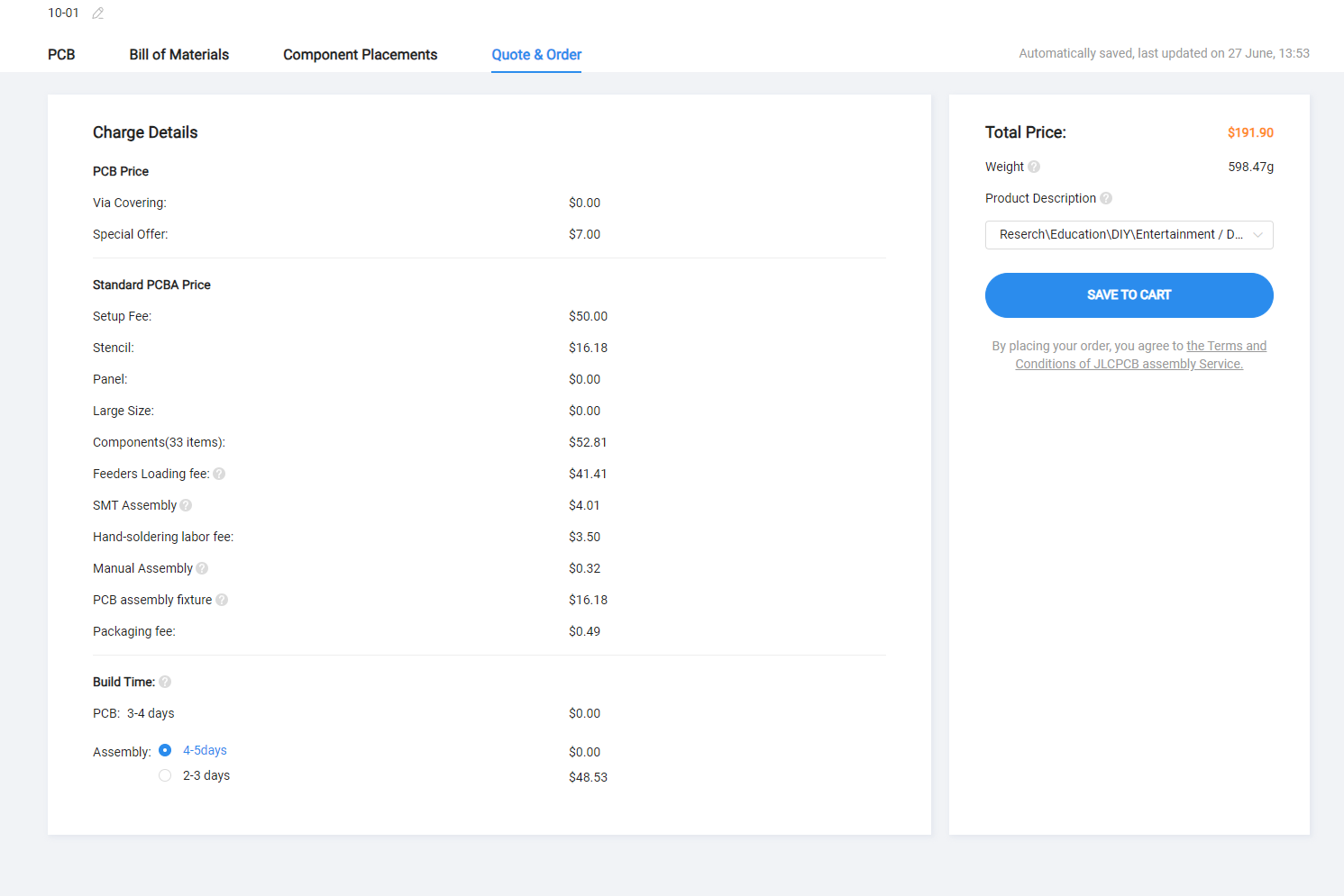
At last you get a summary of the cost of the assembly. Click save to cart and you should be able to pay for the board.
![]()
Using the PCB assembly can be quit expensive when you only need a single board. If you have some skill with a soldering iron and some spare time you could order the pcb from JLCPCB and the parts from Digikey, and then assemble the board yourself.
-
3Order non jlcpcb parts
You will need a few more parts to complet you assembly.
- A 18650 li-ion battery rated for 20A+. I am using Sony 18650 VTC5.
- 4x m2 threaded brass inserts
- 4x m2 22mm screw with hex head
- a 2.4" display from adafruit, partno 618
- A 12mm brass rod
- black and red paint
-
4Turn the binding posts
I have been making my own custom binding posts.
I am using 12mm round stock in brass to make the binding posts
There is two parts to the binding post, the core and the nut.
You will have to take look at the mechanical drawing to se all the dimentions.
Core
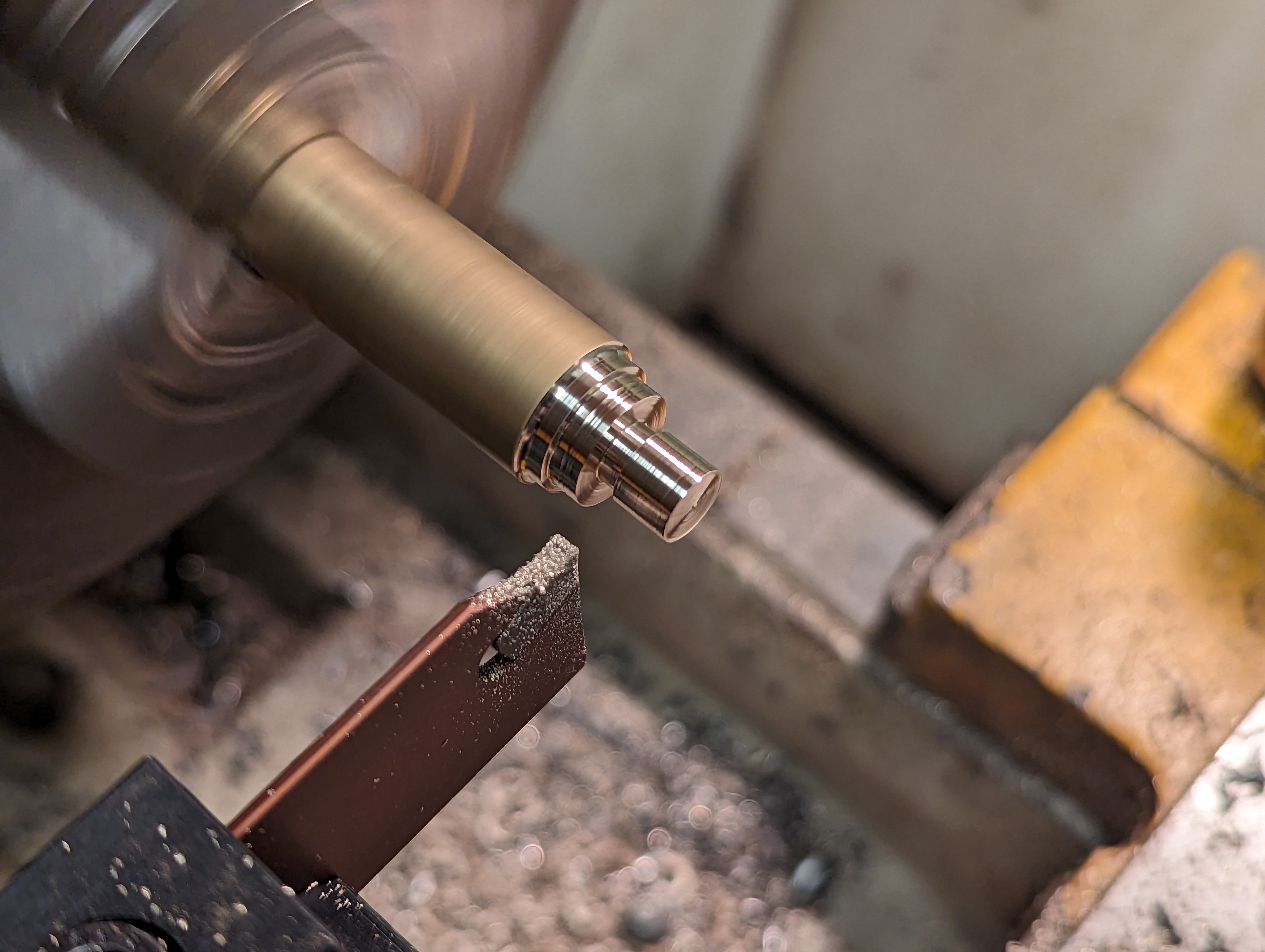
Start with inserting a bass rod in the lathe and face off the end.
![]()
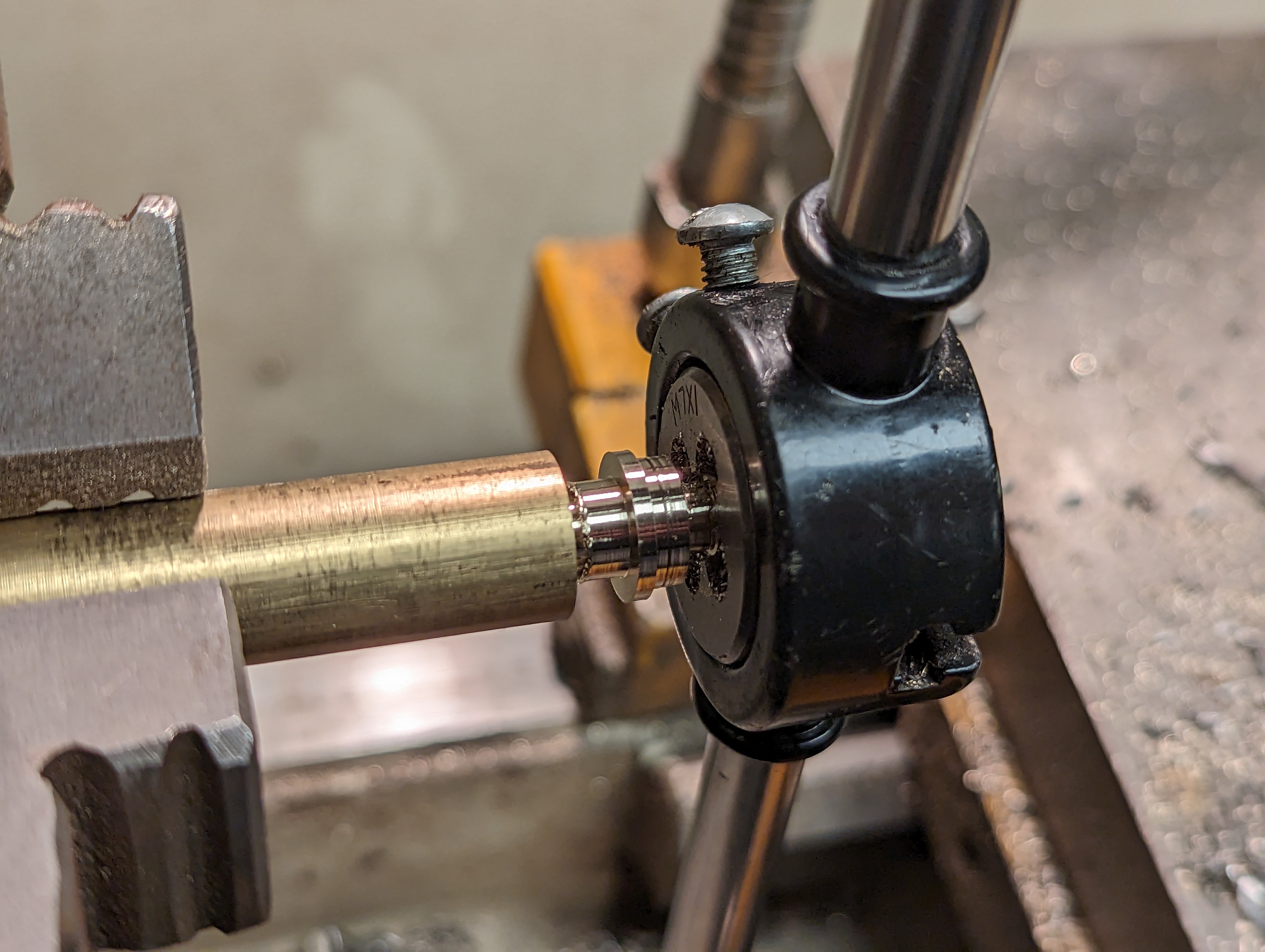
Then create the part that will hold the treads.
![]()
Then use a threding tool to create the treads
![]()
Drill a hole thrugh the part
![]()
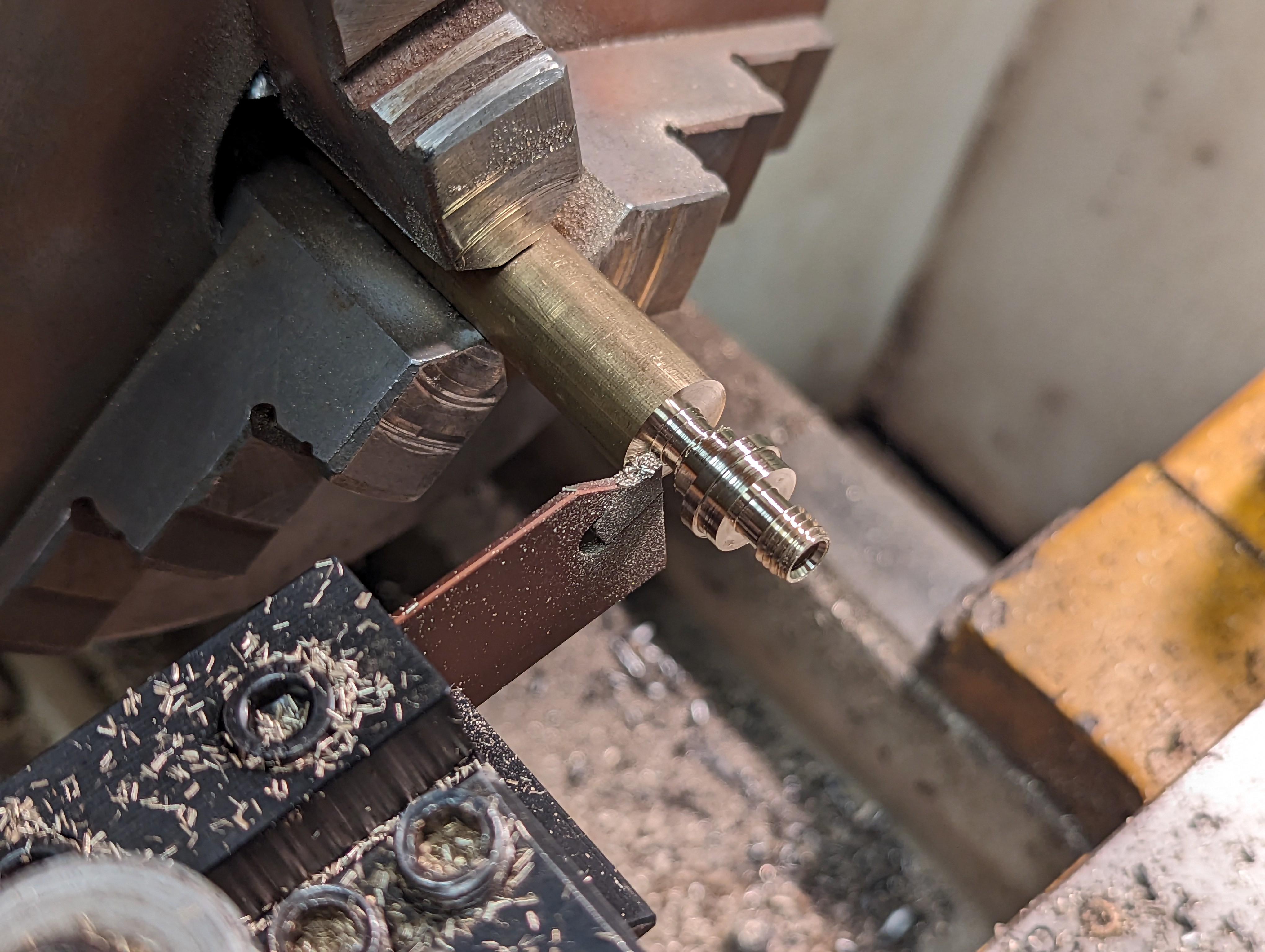
and then turn the last half of the part
![]()
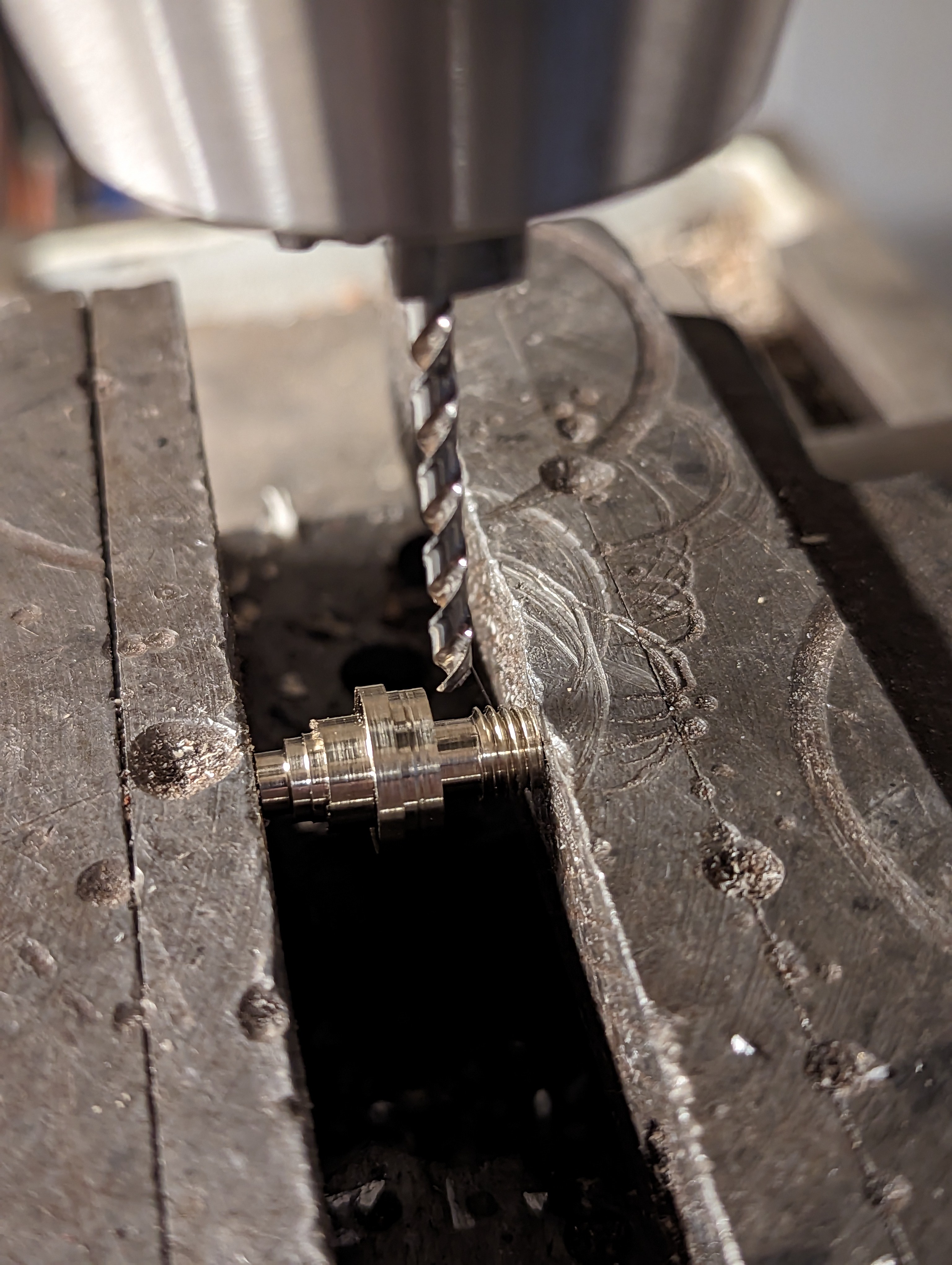
The last part is to drill a hole just below the threads
![]()
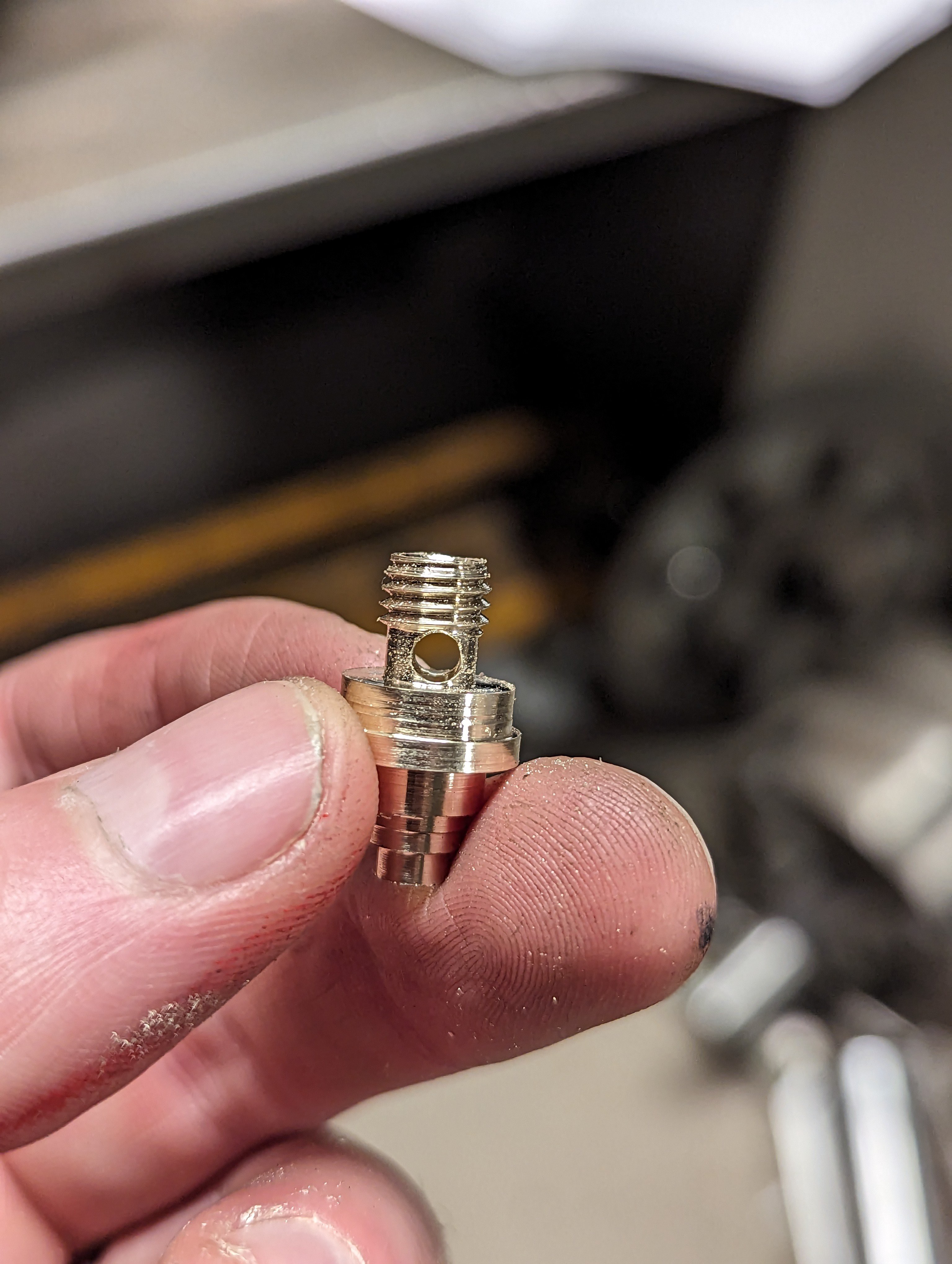
You should then end up with something like this
![]()
When creating the nut, start by dimentioning the outide of where the knurling will be.![]()
Drill a hole thrugh the part
![]()
Use a larger drill to remove some some of the brass there we don't want threads
![]()
Make threads inside the hole
![]()
Add knurling to the outside
![]()
Lastly take away some of the knurrling at the bottom of the nut.
![]()
The nut should now fit onto the core.
![]()
-
5Solder on parts
You will have to solder on the display and the binding posts.
Use the tape on the back of the display connector to hold it in place while soldering.
Be aware so that your soldering iron do not touch the rest of the display. It is really easy to burn a hole in the black plastic cover on the back of the display.
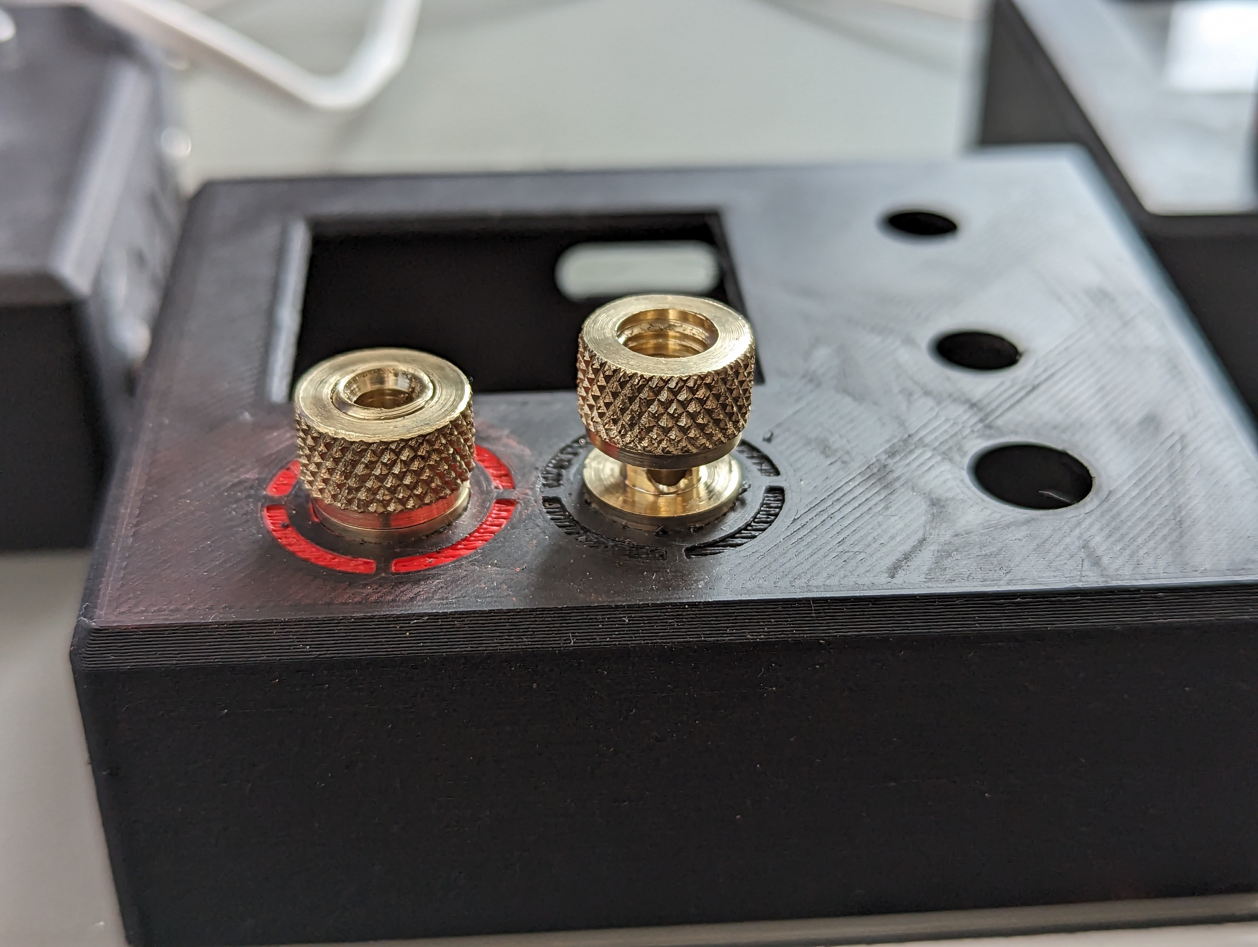
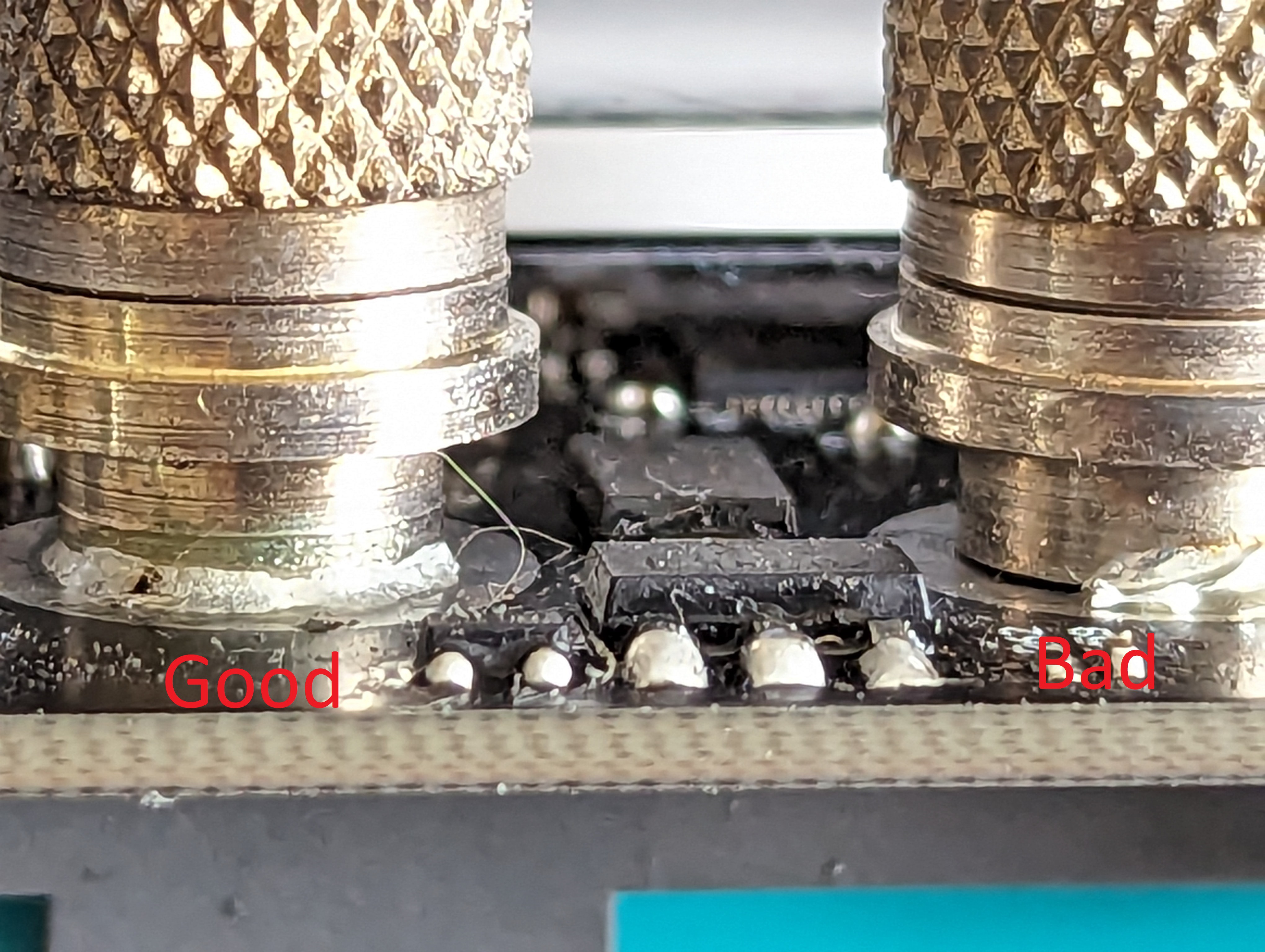
When soldering the binding post, align the binding post so that the holes inside points up/down, not right/left. Then use a loots of heat add be patient, make sure the solder is melting and flowing. You should see solder coming up on the other side where you applied it.
![]()
-
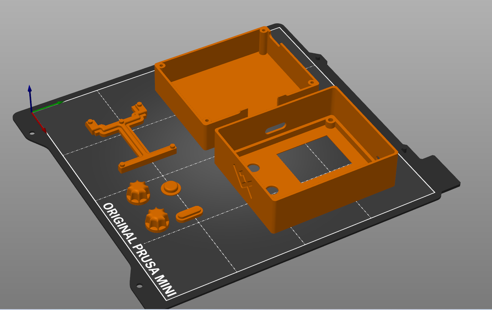
63dPrint enclusure
A few parts need to be 3d printed. I am using matt black and white PLA.
you will need:
- 1 frontpanel (black)
- 1x backpanell (black)
- 2x enckoder knobs (white)
- 1x on/off knob (white)
- 1x power knob(white)
- 1x display holder (any color, not visible)
![]()
![]()
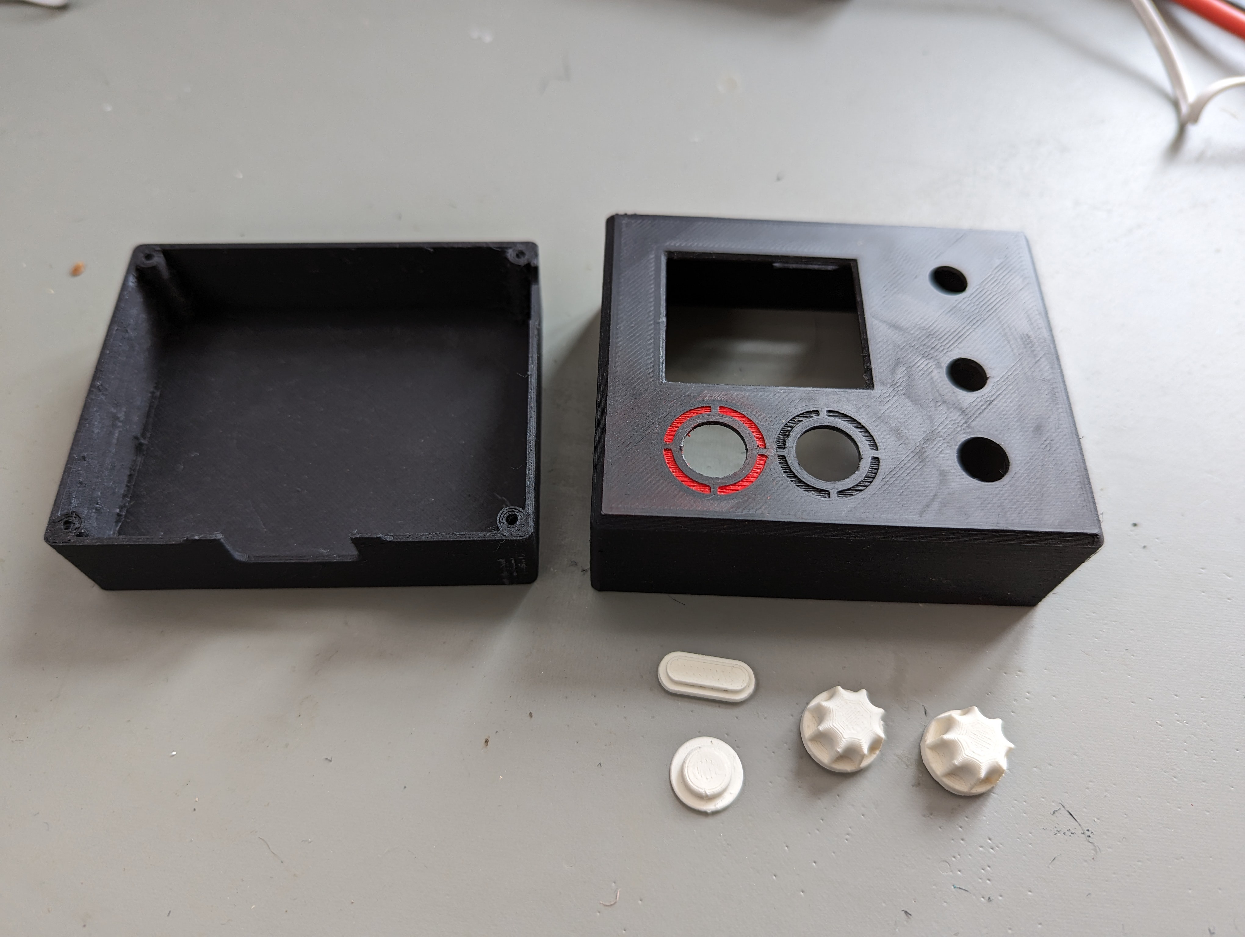
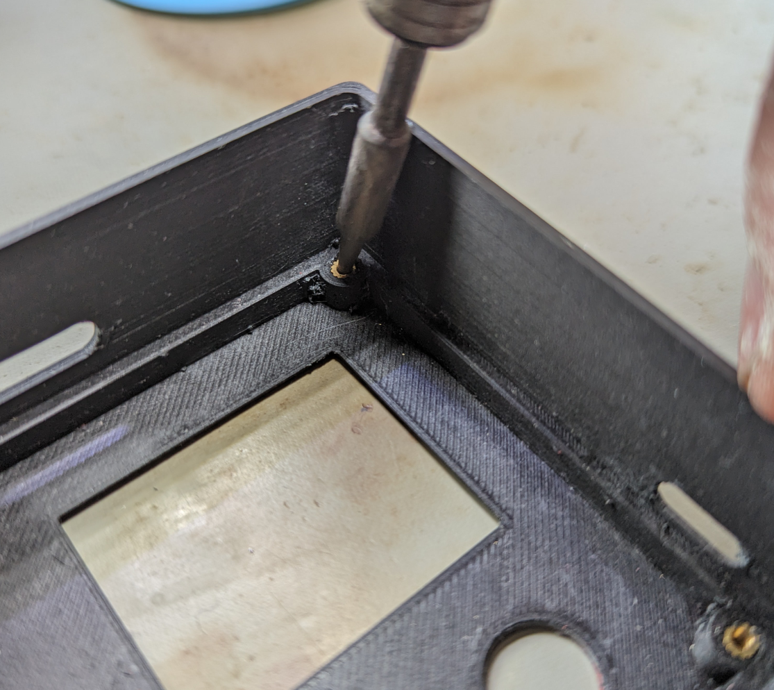
The frontpannel has space for 4 m2 threaded inserts. Heat up the inserts and press them inn. I use a soldering iron to heat the inserts.
![]()
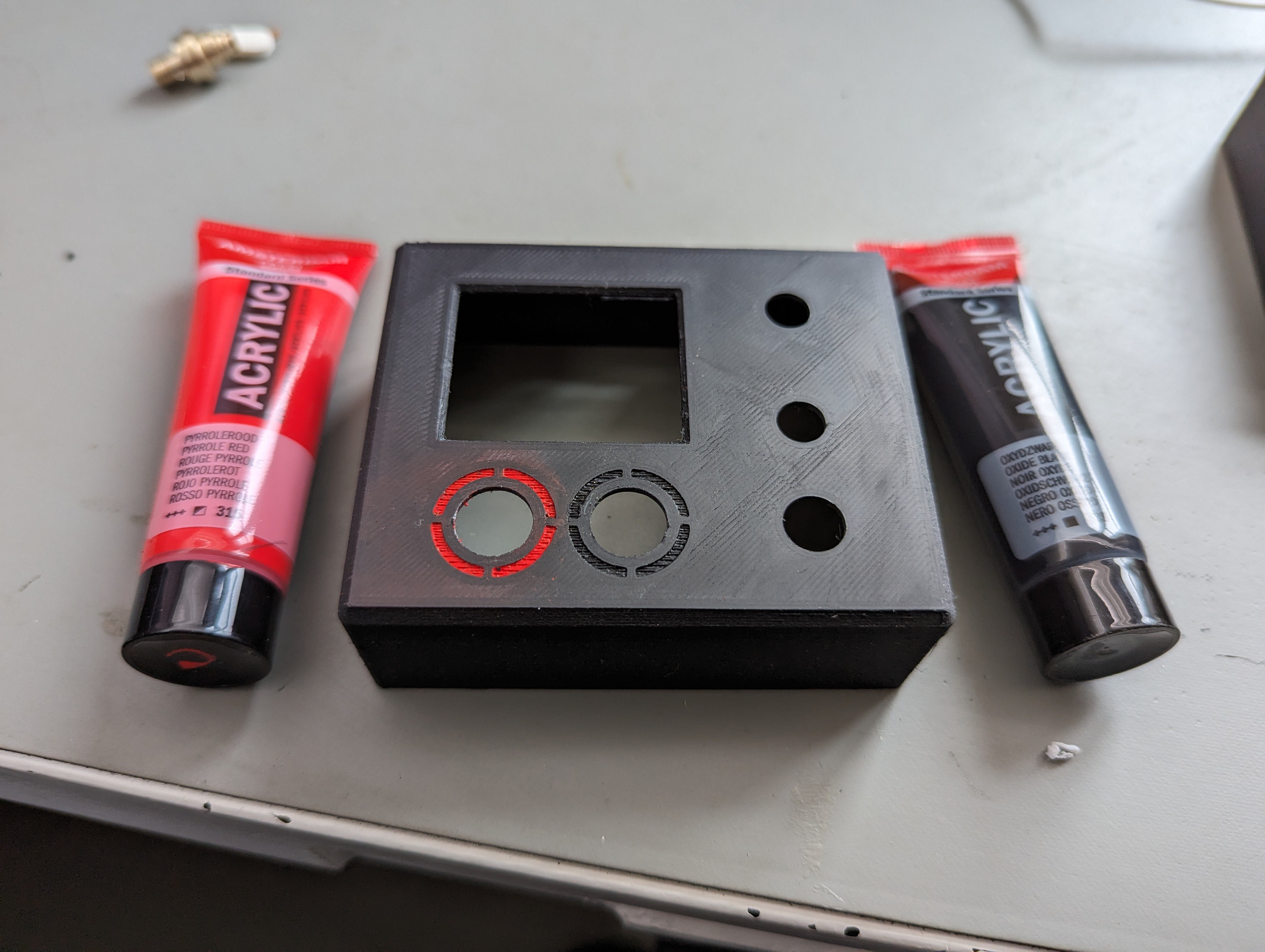
The grooves in int the front panel should have some paint in them to mark + and -. The one to the left should be red(+) and black(-) to the right.
![]()
-
7Upload software
- hold down on/off button
- plugg in usb-cable
- A usb stick device should show up on you computer
- copy .u2f file into the folder
- unplug usb-cable
- plug usb-cable back in
- press powerbutton
- The device should power on.
-
8Assembly
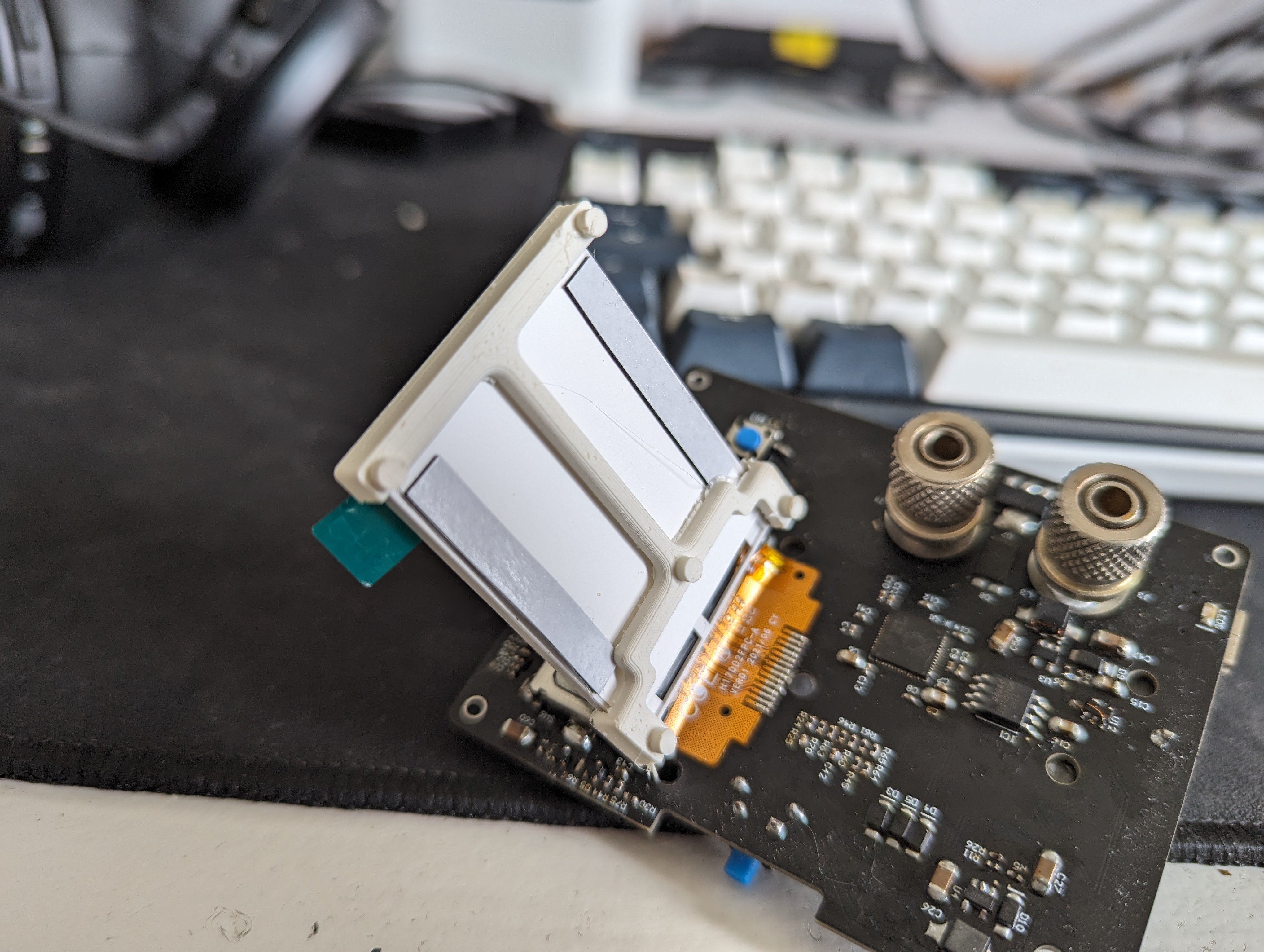
- Start by placing the display holder between the pcb and the display.
![]()
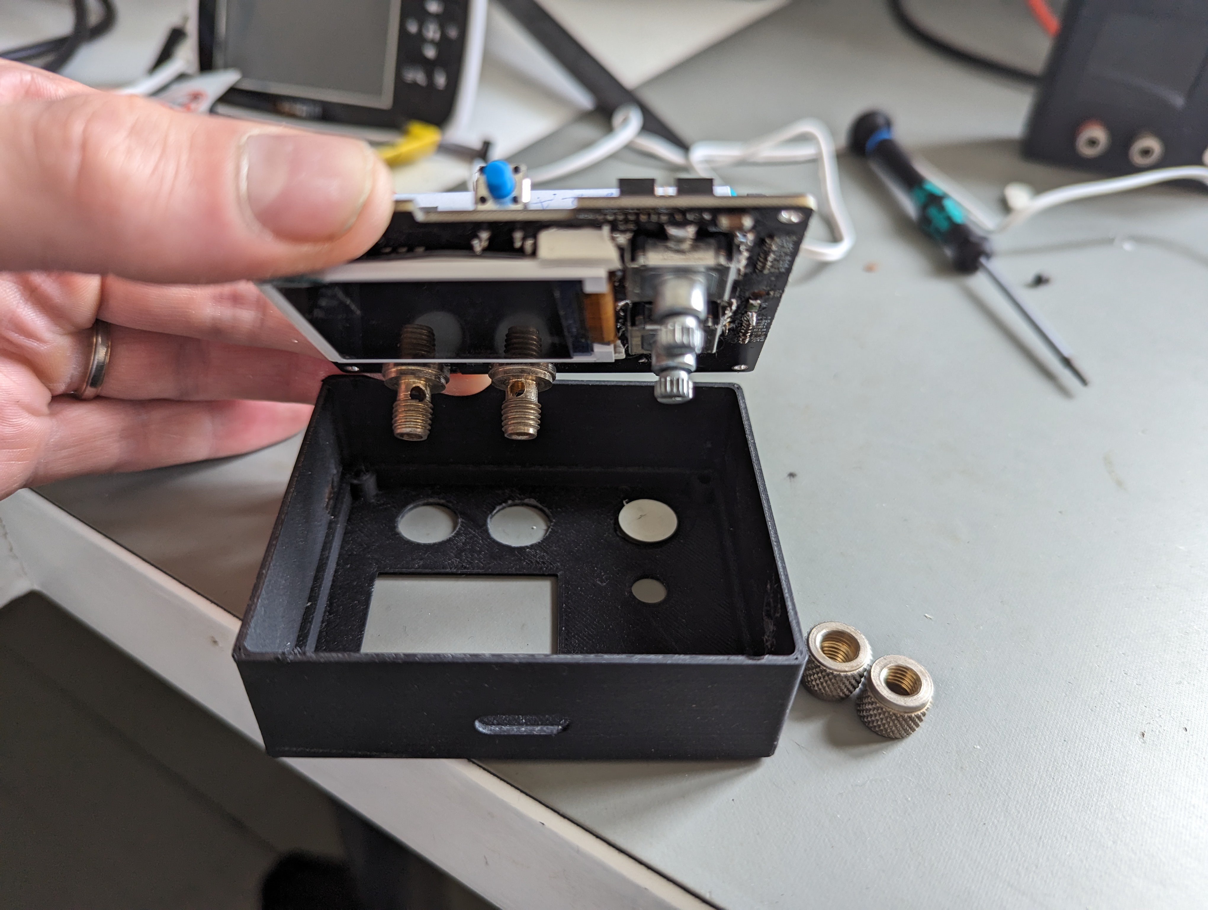
- unscrew the binding post nuts
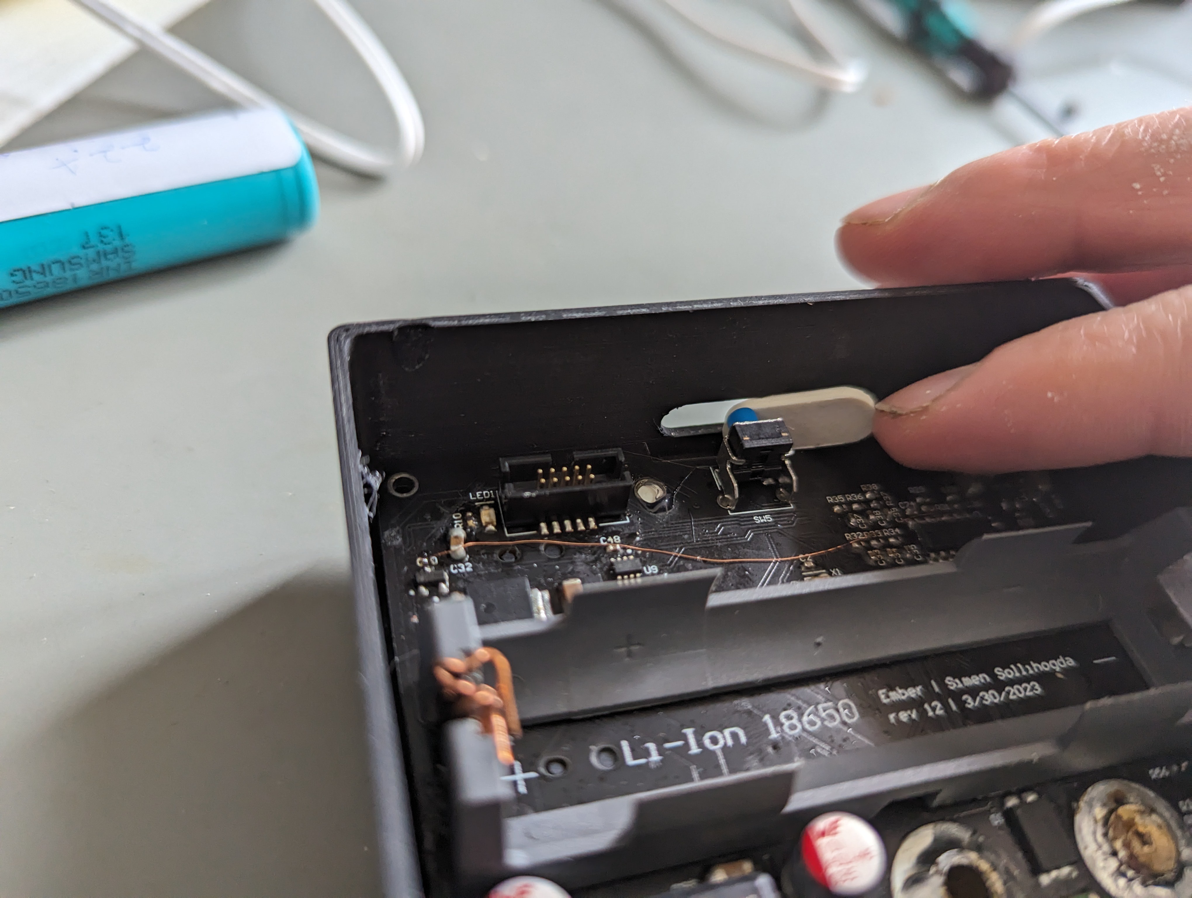
- place the on/off button inside the hole in the front panel
- press the pcb down in the front pannel
![]()
- place the power button
![]()
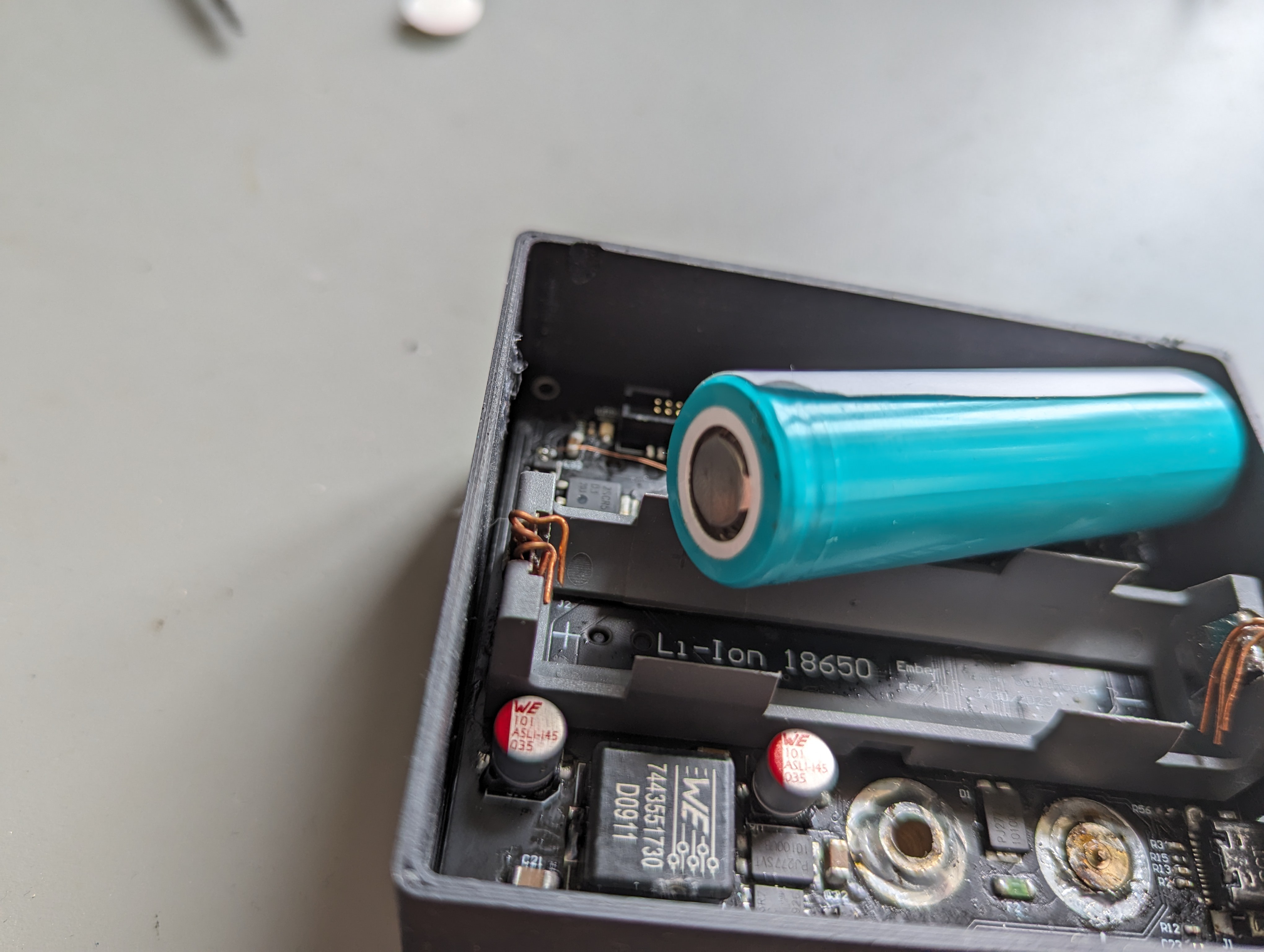
- add the battery. Make sure it's the right way, the bump is the positive side.
![]()
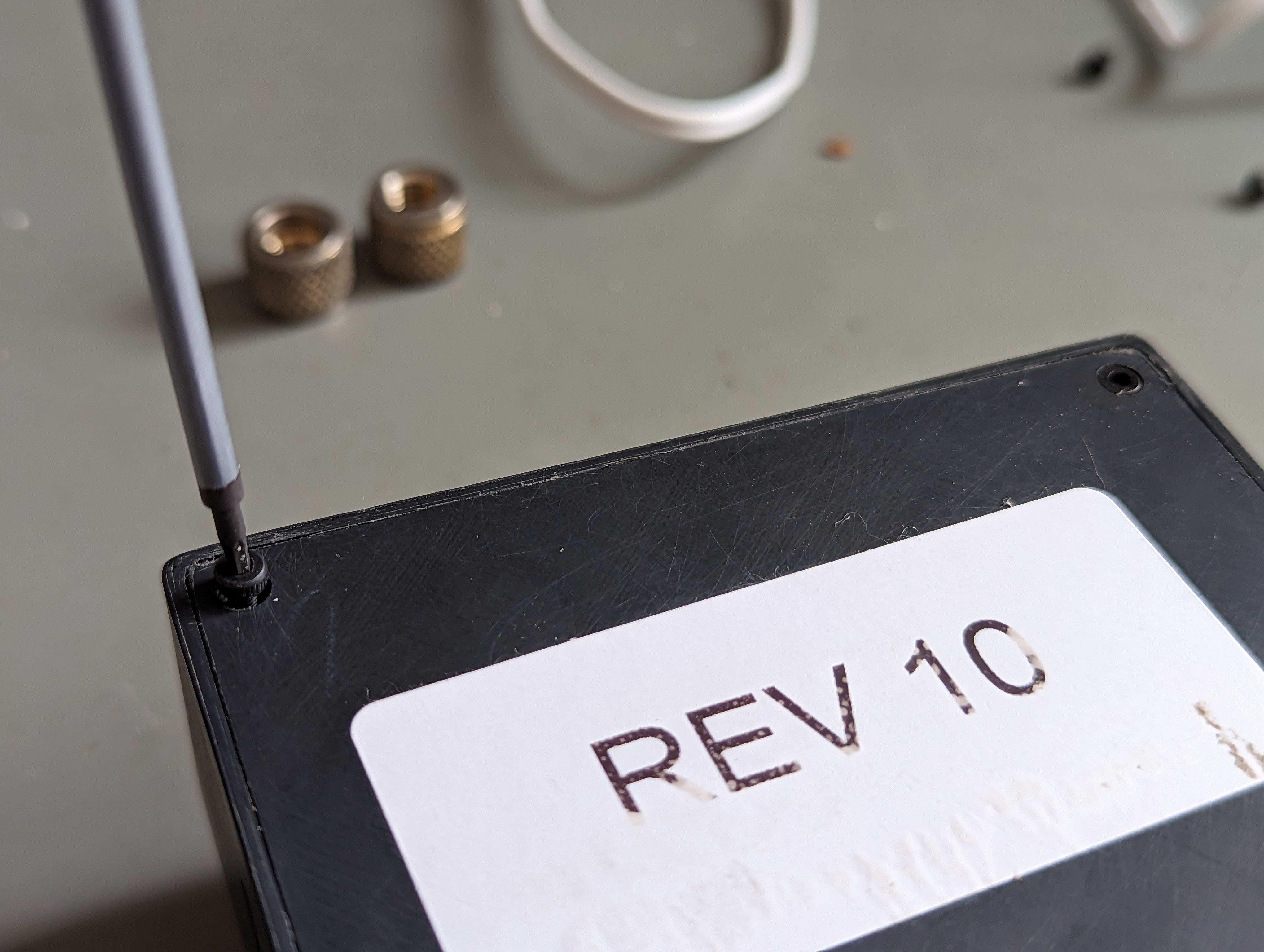
- close with back panel
- screw in 4x m2 screws
![]()
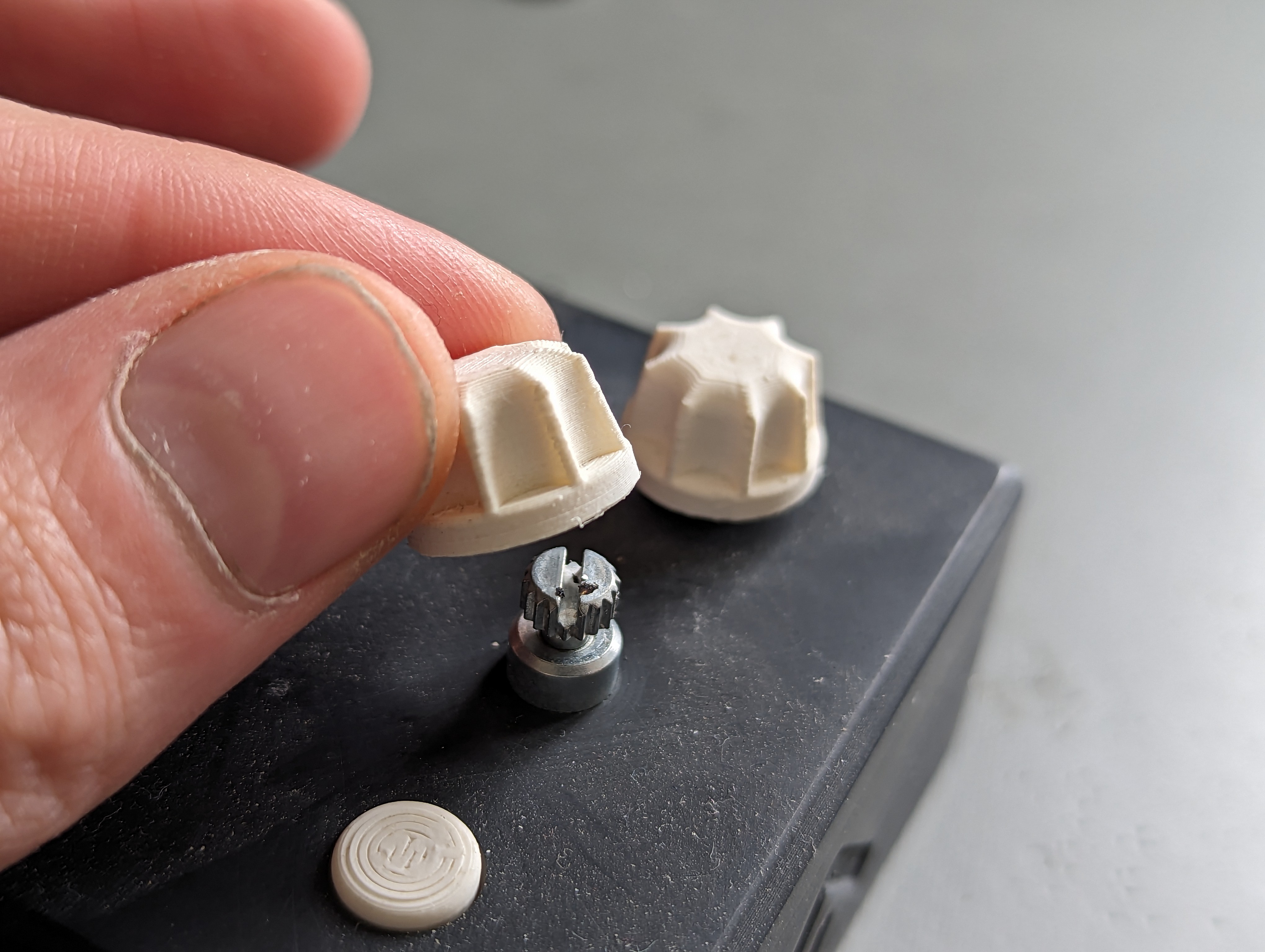
- screw back bindipost nuts
- heat encoders and press on enkoder knobs.
![]()
- Start by placing the display holder between the pcb and the display.


Discussions
Become a Hackaday.io Member
Create an account to leave a comment. Already have an account? Log In.