alnwlsn
-
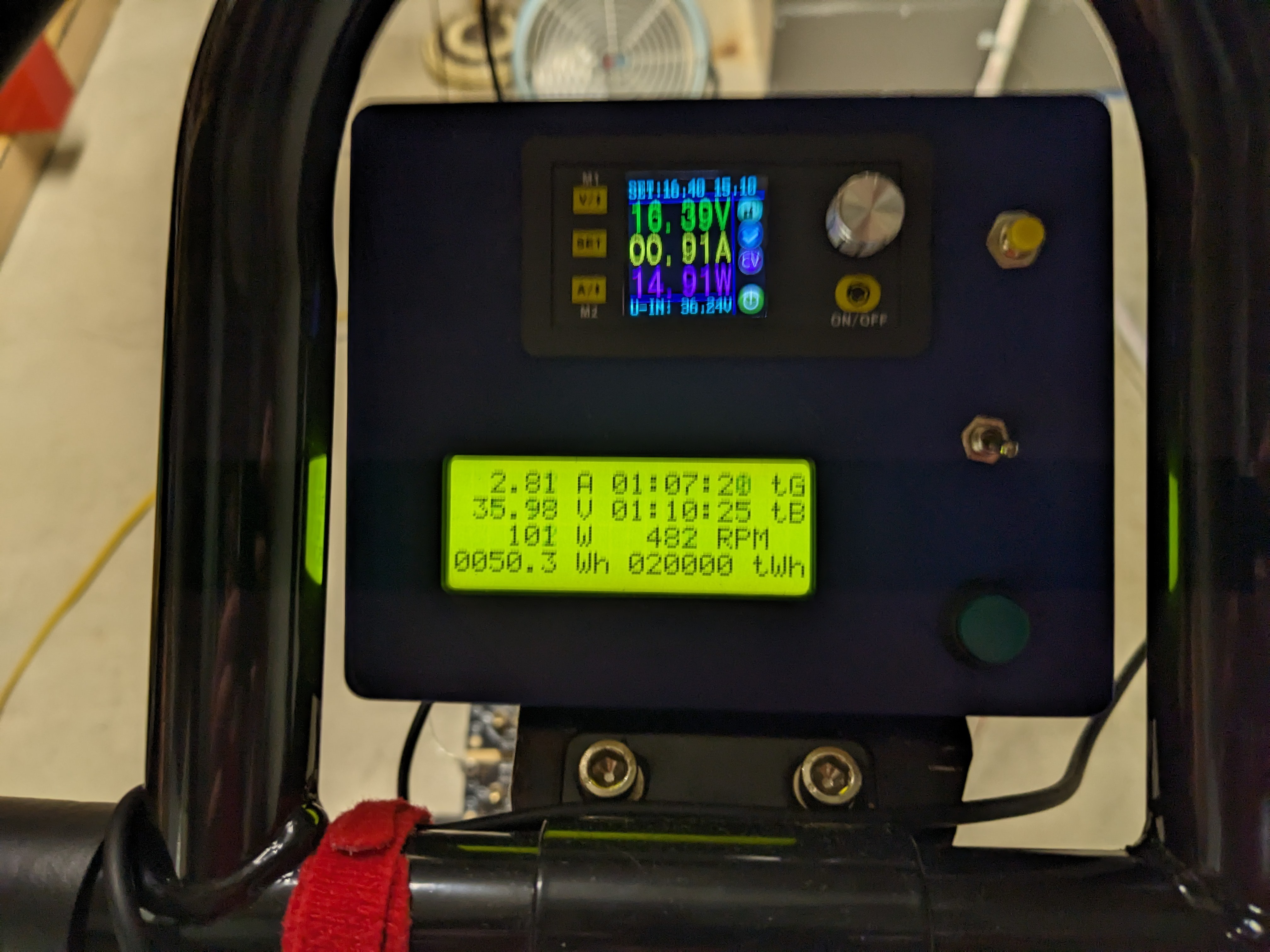
Another year, another 10 kWh
12/22/2023 at 03:10 • 0 commentsMy watt-hour-ometer just rolled over to 20000 total watt hours just minutes ago. Hard to believe its been 2 years of this project, cracking away at a lazy ~50 Wh / hour, on most days. That's 16.66 continuous days of cycling. For that work, I am rewarded with 20 kWh of energy. That's almost enough to power 2/3 of the average American home - for ONE DAY! But, I don't feel like stopping, so I guess I'll keep pedaling another year to make a full day's supply.
This message was posted from 100% bicycle power.
![]()
-
Back in Business
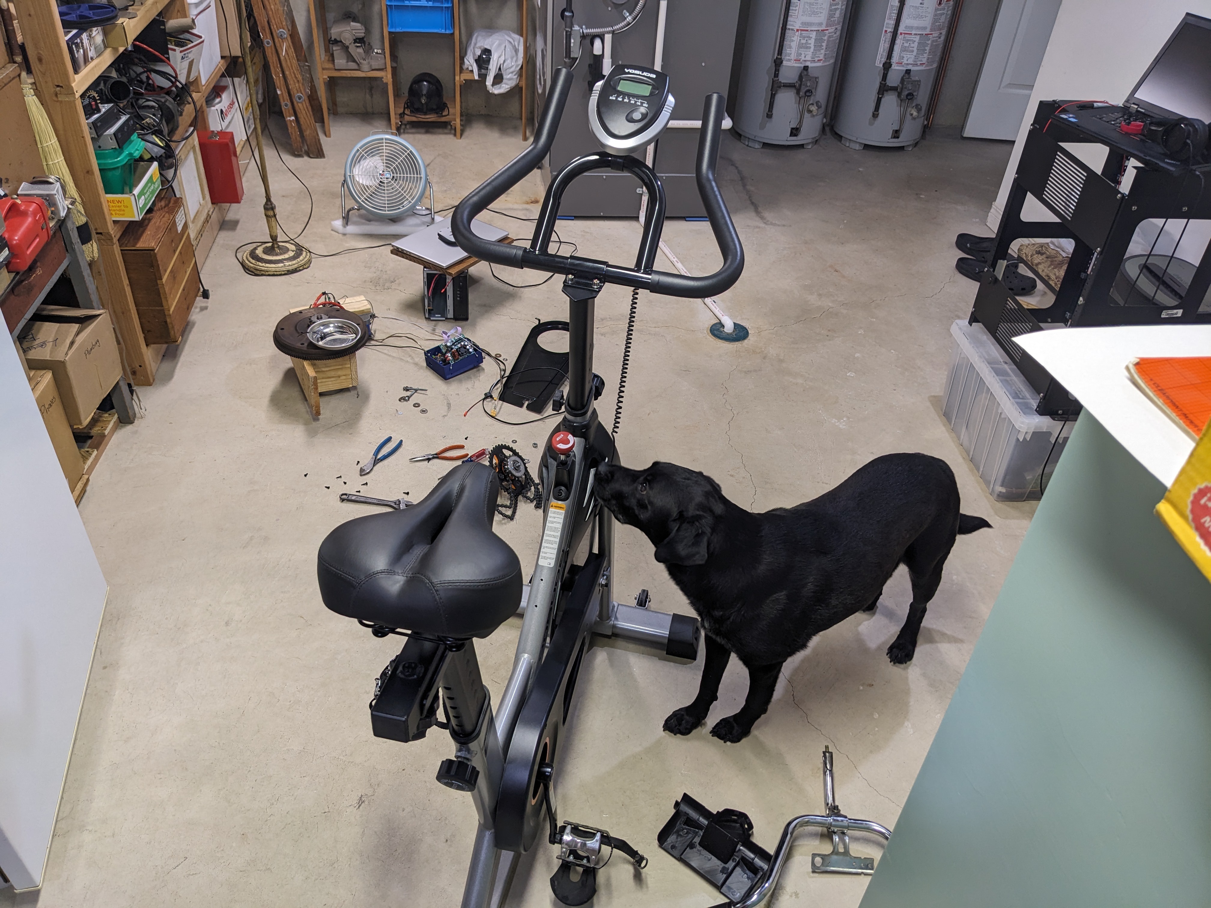
07/29/2023 at 03:19 • 0 commentsAfter last week's failure, I decided that I was really due for an upgrade. The old frame was made as cheaply as possible to begin with, and there's a good selection of decent modern frames that are a lot more robust. You can pick up one on Amazon right now and have it shipped to your house for a few hundred bucks. Or, you can go on Craigslist and pick up a used one for cheap. Since I only really cared about the frame and pedals, that's the direction I went, and picked up this specimen for $65.
![]()
After a few days, the conversion was finished. Sorry for not taking a lot of pictures, but I'll hit the highlights.
![]()
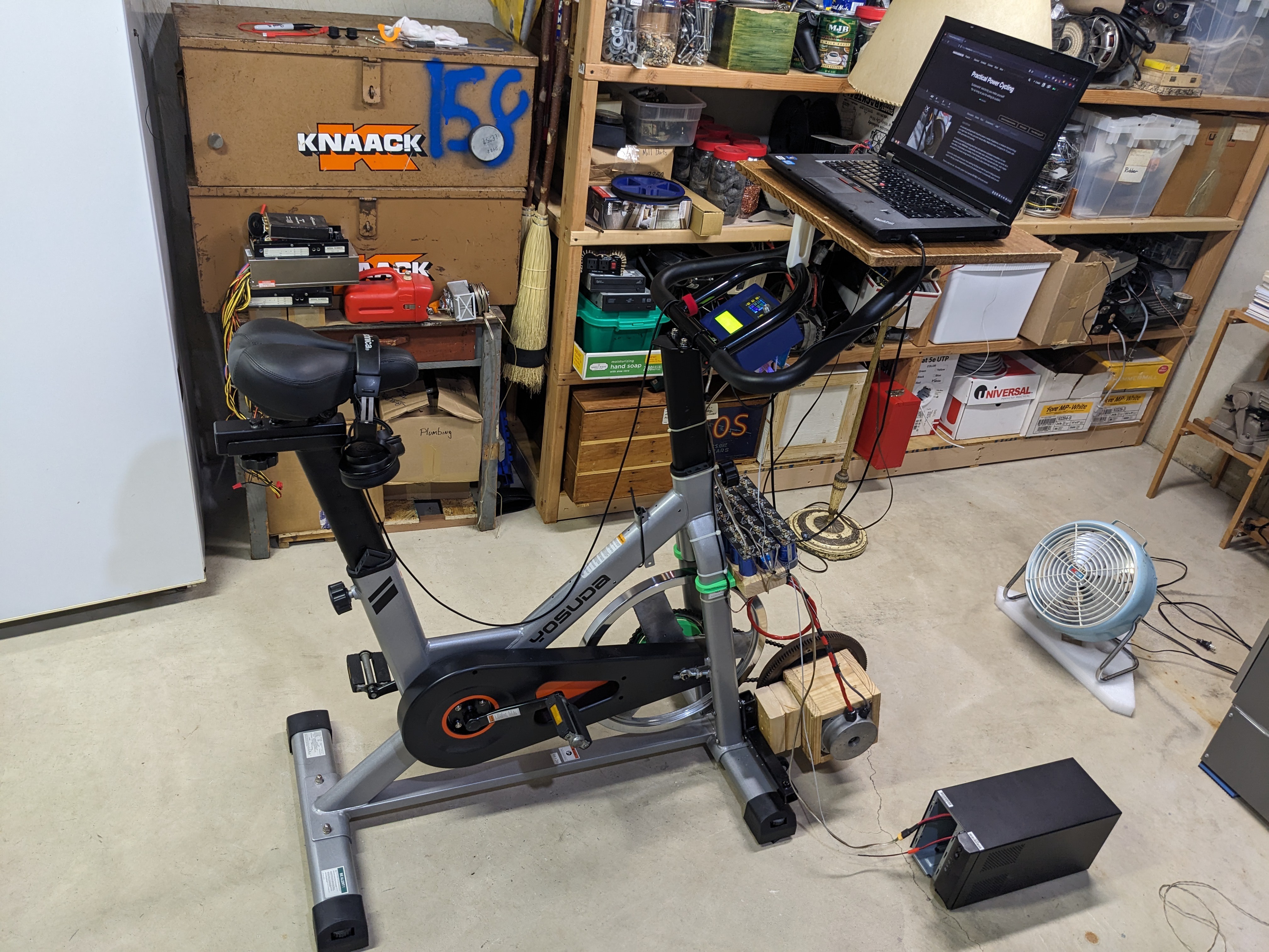
The bike seems to be the Yosuda L-001A. I don't know much about Yosuda or the stationary bike market, but it seems you can get this on Amazon for about $320. It seems to be entry-ish level from what I've seen, with a felt pad brake (now removed) instead of some kind of fancier (and quieter) magnetic version. The frame is significantly heavier duty than my old one. Also, like seemingly all of these modern bikes, it is belt driven, probably for noise reasons, as without the generator and its chain, it is dead silent. On the other hand, the belt needs to be pulled extremely tight or it will slip, and there is also no ratchet mechanism, meaning that the heavy flywheel and pedals are always locked together. This can be dangerous; if your feet slip off the pedals they will keep going and bash up your legs. This is probably why the pedals come with straps to hold onto your shoes. Since I don't like wearing shoes, I swapped out the pedals for some flat ones, and I'll take the risk. If anything bad happens I will let you know.
![]()
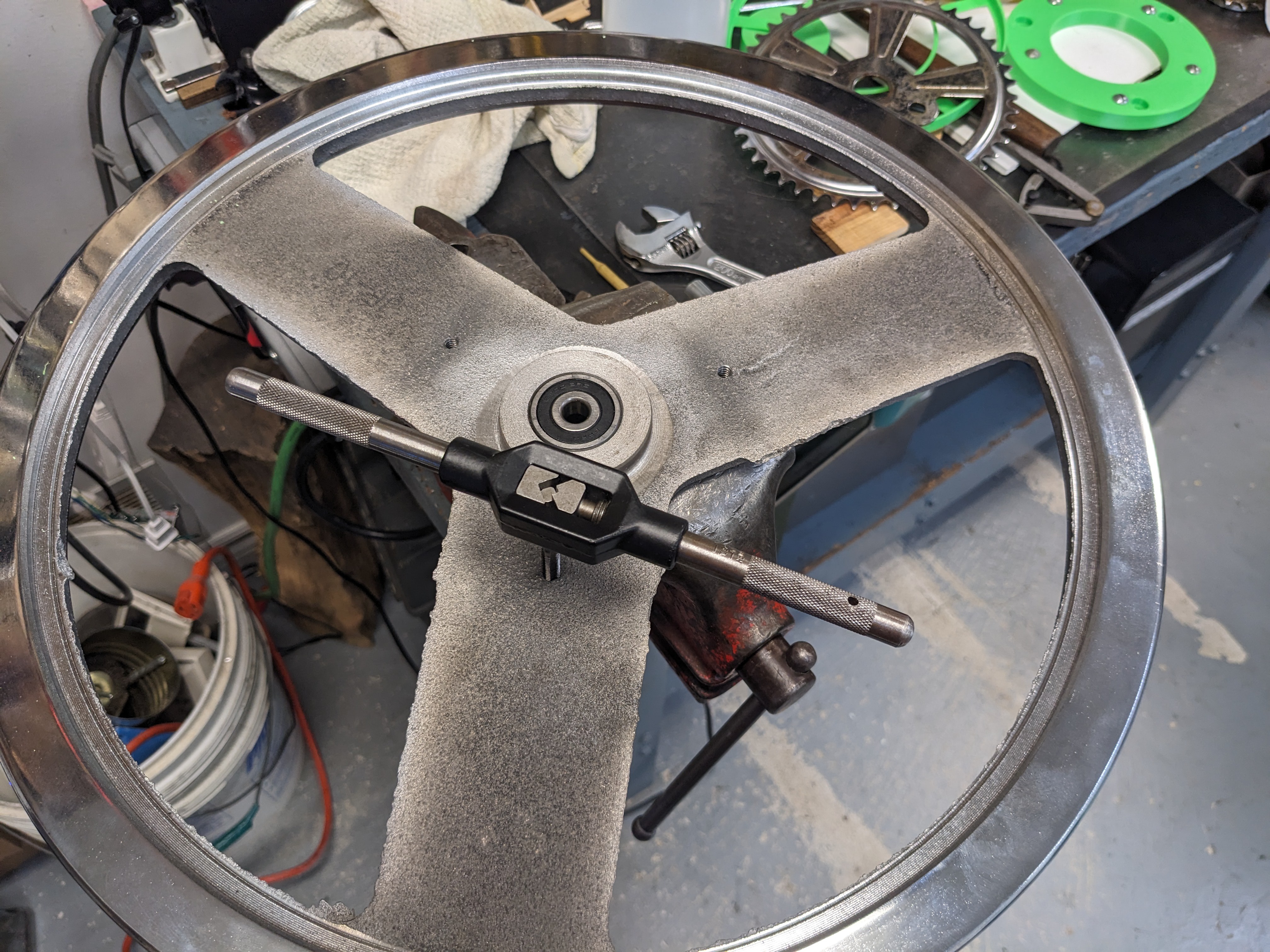
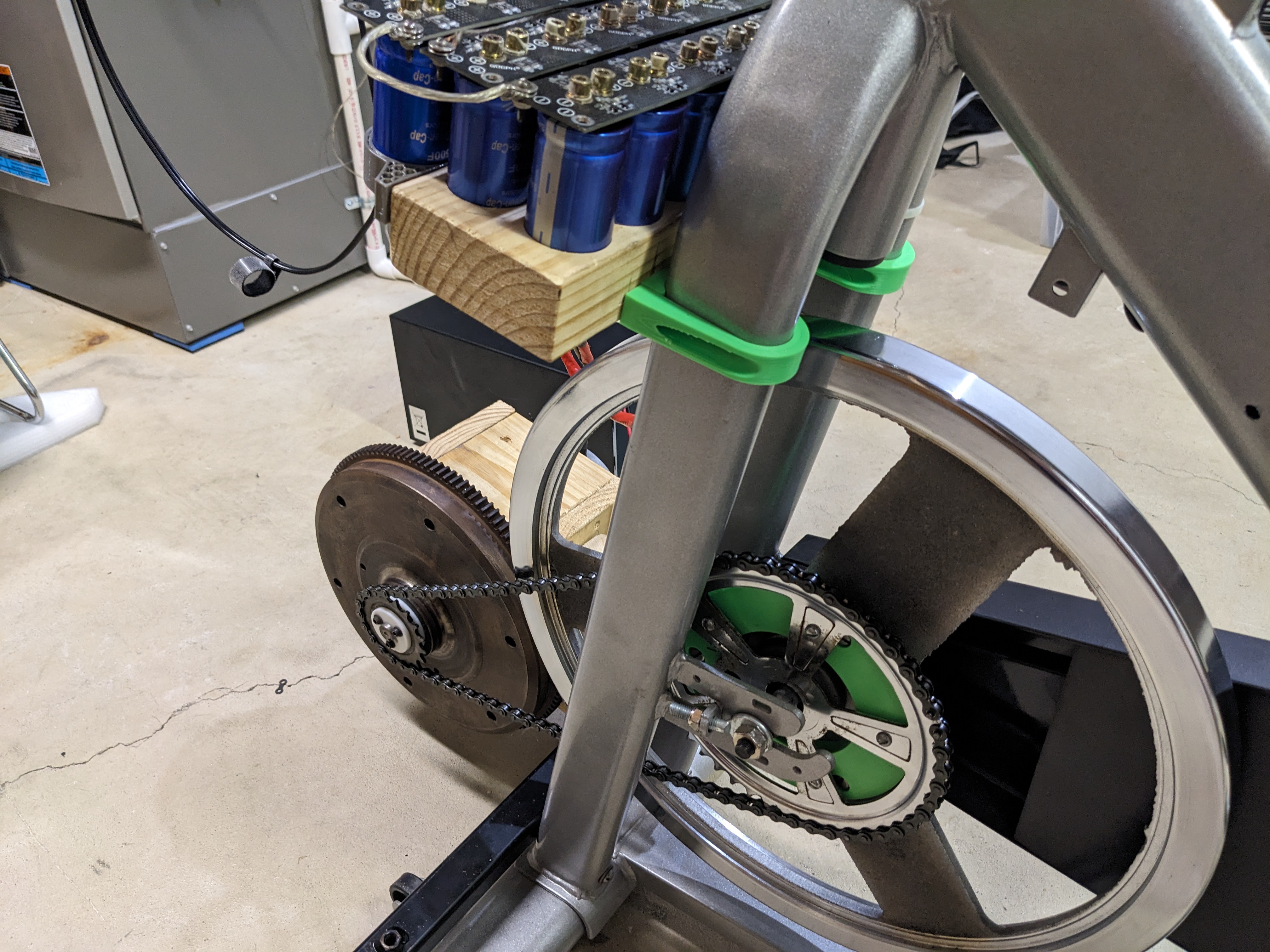
The supposed 35lb flywheel measures in at about 22lb on my scale, which is probably a good sign to get one of the two checked. The wheel shows no evidence of drilling for balancing, but does seem to be reasonable regardless. The front pulley is built into the casting, so I figured I would keep the flywheel for now. It is cast iron, making it very easy to drill and tap. However, it would not fit onto my drill press or lathe, so I just sort of had to eyeball it and use handheld tools. I mounted a bicycle chain sprocket rather than the thick chain I bought earlier, since the space between the wheel and frame was not as generous as the old jackshaft solution. It ended up fine; bike chain is rather forgiving. I doubt I would have been able to setup a good, concentric pulley setup here. The chain is, of course, much nosier than the belt, but since I operate this in the basement and always wear headphones, it's acceptable.
![]()
The generator similarly had to be relocated, and new shaft adapters made to connect a bicycle chain sprocket. Initially, I had hoped to
eliminate the VW flywheel (after all, I kept the original bike flywheel) but I quickly realized why it is so important. The first test run without the VW flywheel was very noisy, with massive vibrations running through the frame and into the pedals. It felt like riding on a very bumpy road, or highway rumble strips. What this was is motor pole noise; as the armature moves between poles the torque required is less. This vibration travels up the chain like a string can telephone and vibrates the whole frame. I had to add some wood blocks to get enough space to add the flywheel back. The wood blocks are pretty inaccurate as far as lining things up, but it is very easy to adjust and modify.![]()
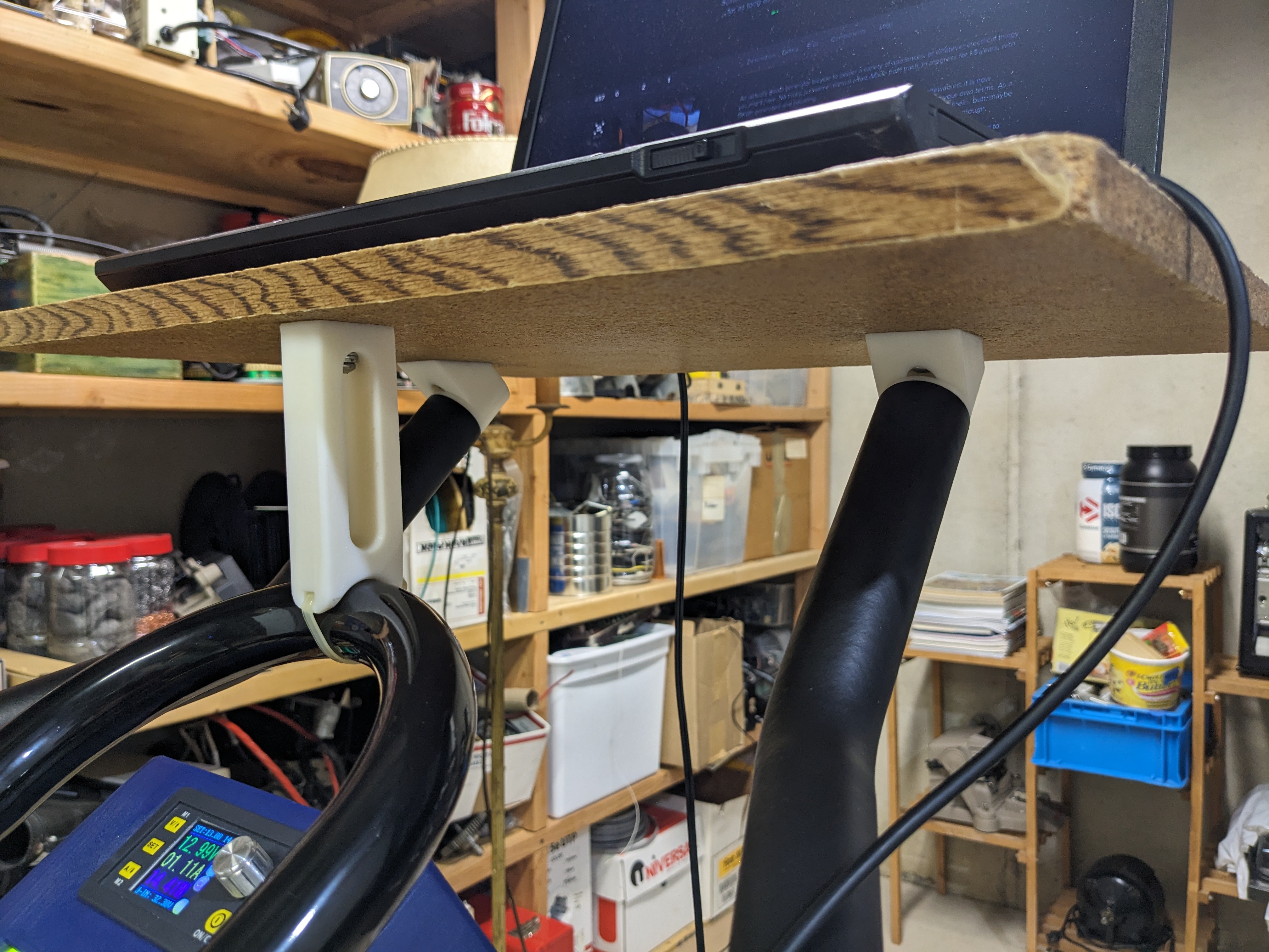
The capacitors and gauge cluster were added in with new mounts wherever they would fit, in similar locations to the original. The one new change I made was to add a shelf for my laptop on top of the extra long handlebars. I made a pair of 3D printed expanding collets to fit in the end of the tubes which would accept a bolt, which was then bolted to a bracket to hold the shelf. Finally, I added a stabilizer at the front of the shelf to stop it flexing when I rested my hand on top to operate the mouse or keyboard. The laptop is too far away to operate comfortably while cycling, but I'd good for watching videos, and far better than the stack of boxes I used to use to hold the laptop, which was slightly off to the side. It's going to be a much better experience looking straight ahead instead of off to one side, too.
![]()
In line with the move to belt drive, the new bike chain to the generator allowed me to upgrade the gear ratio from about 6:1 to about 8:1, which is something I had been wanting to do for a while. It was taking a little too high speed to comfortably keep the 120V inverter running at a good voltage.
-
Unexpected turn of events
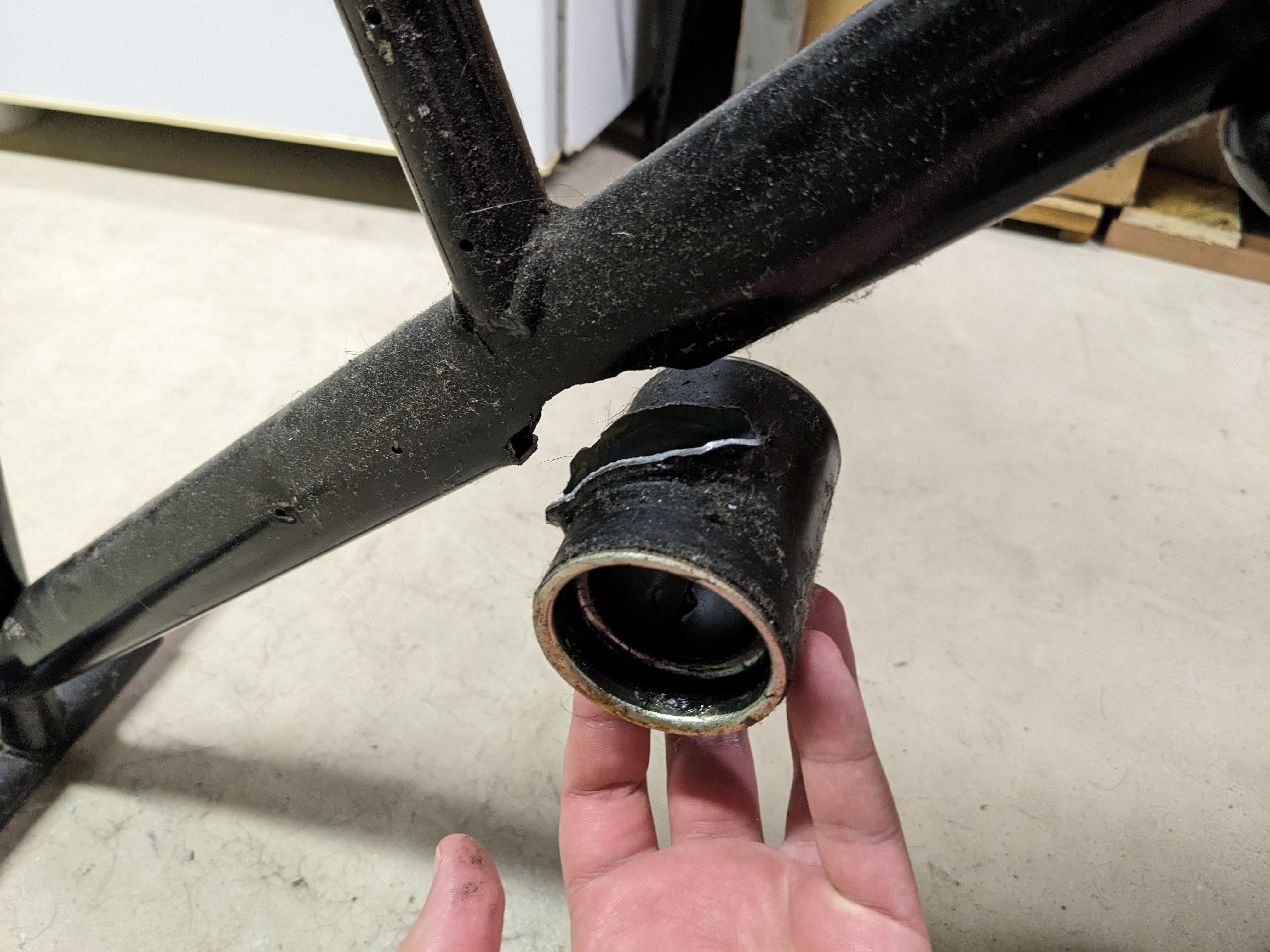
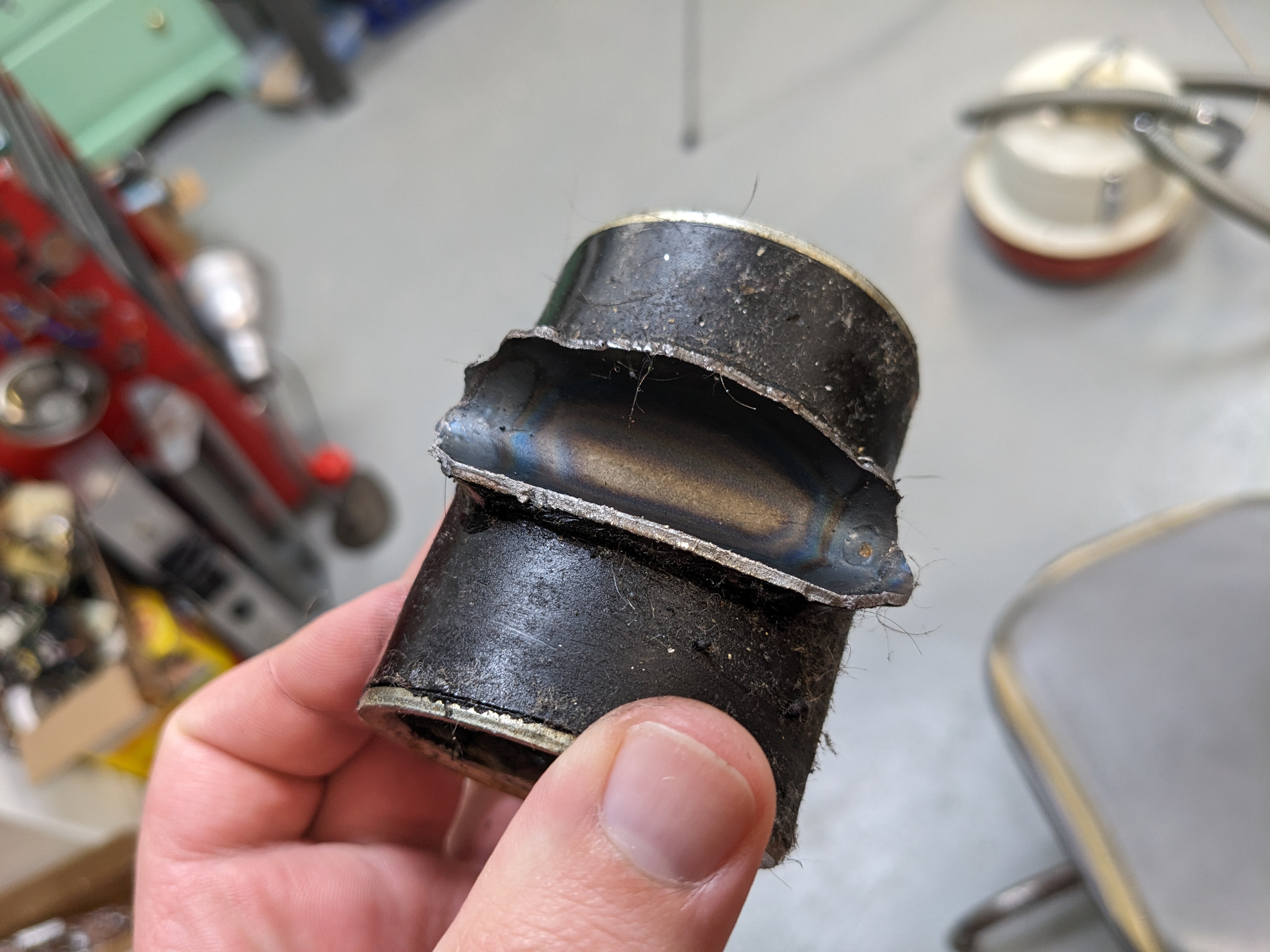
07/21/2023 at 03:03 • 0 commentsWhere will you be when metal fatigue strikes? I knew something was wrong today when I started pedaling and the chain fell off. While trying to put it back on, I found the pedal bearing was extremely loose. Only a couple tugs with one hand and the entire bearing housing broke clean away.
Let's do a bit of estimation here. I had passed 15600 watt-hours when this happened, and I'm going to guess that my typical rate is about 50 watt-hours per hour. That's not a lot, but it sounds realistic. Some days are more, some are less. As such, that represents 312 hours of pedaling. If I say that a full cycle of the pedals is about once/second, that represents 312*3600=1123200 cycles, a bit over 1 million. This frame is pretty old, so it's possible in a past life it attained maybe another million or two.
The only question now is if it's worth repairing this old, cheap frame, which is actually too small for me, or, if I should find a better frame.
![]()
Ignoring the layer of greasy dust, we can see that it was the actual frame that failed, not the weld.
![]()
-
Arduino Watt meter
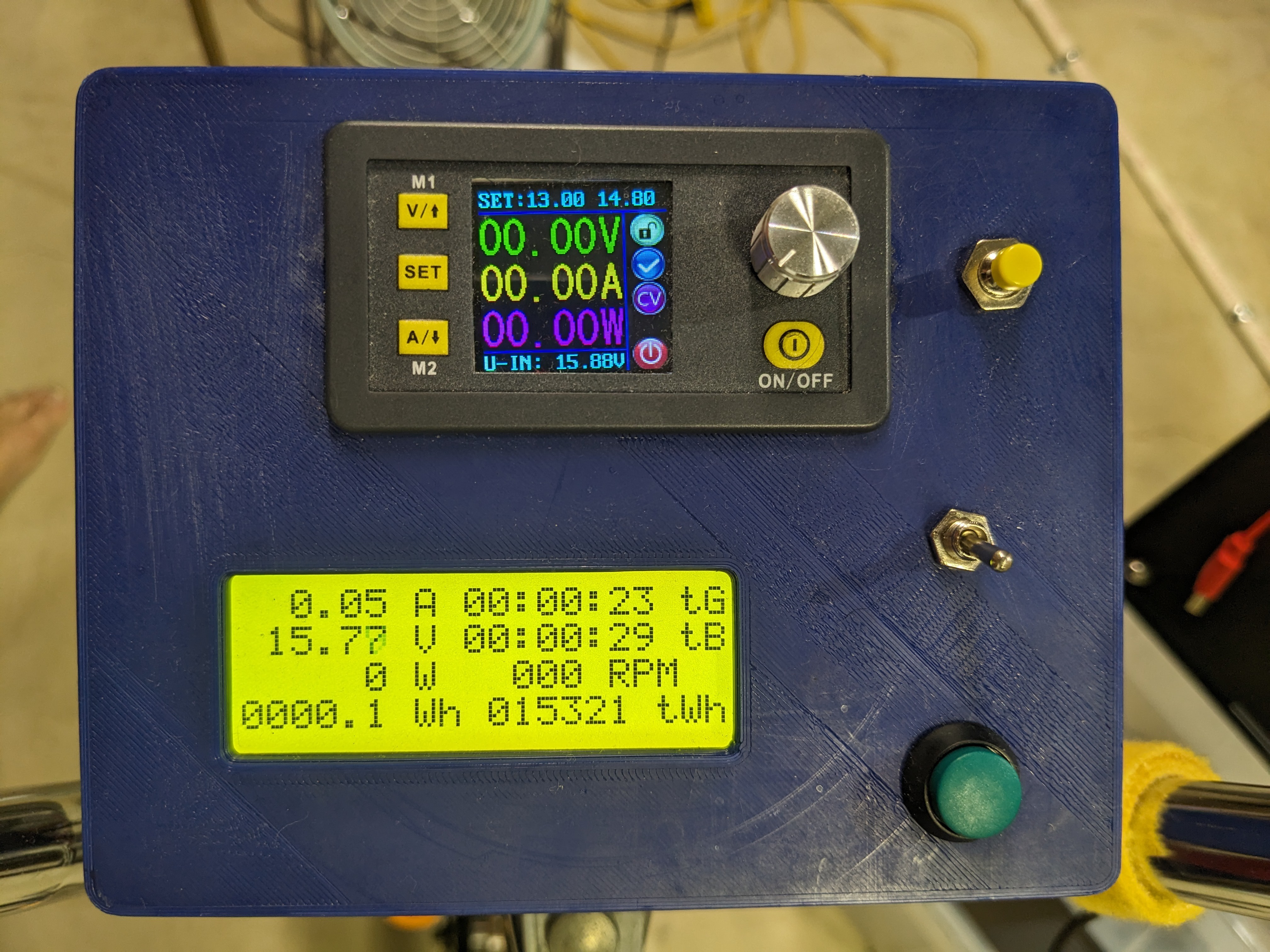
07/09/2023 at 22:32 • 0 commentsThe centerpiece of this project (at least from the operator's perspective) has to be the gauge cluster in the middle of the handlebars. It replaces the original speedometer, odometer, and timer, and provides the equivalents for generating power - volts, amps, watts (power), watt-hours (energy) and 2 stopwatches. This is also the location where I've chosen to mount the DPS5015 power supply. From the outside, it's reasonably clean looking:
![]()
The green button is for the user stopwatch (the tB field), then we have the Arduino power toggle switch, and the yellow button is used to turn on the AC inverter. The controls for the DC power supply are similarly accessible without having to stop pedaling.
![]()
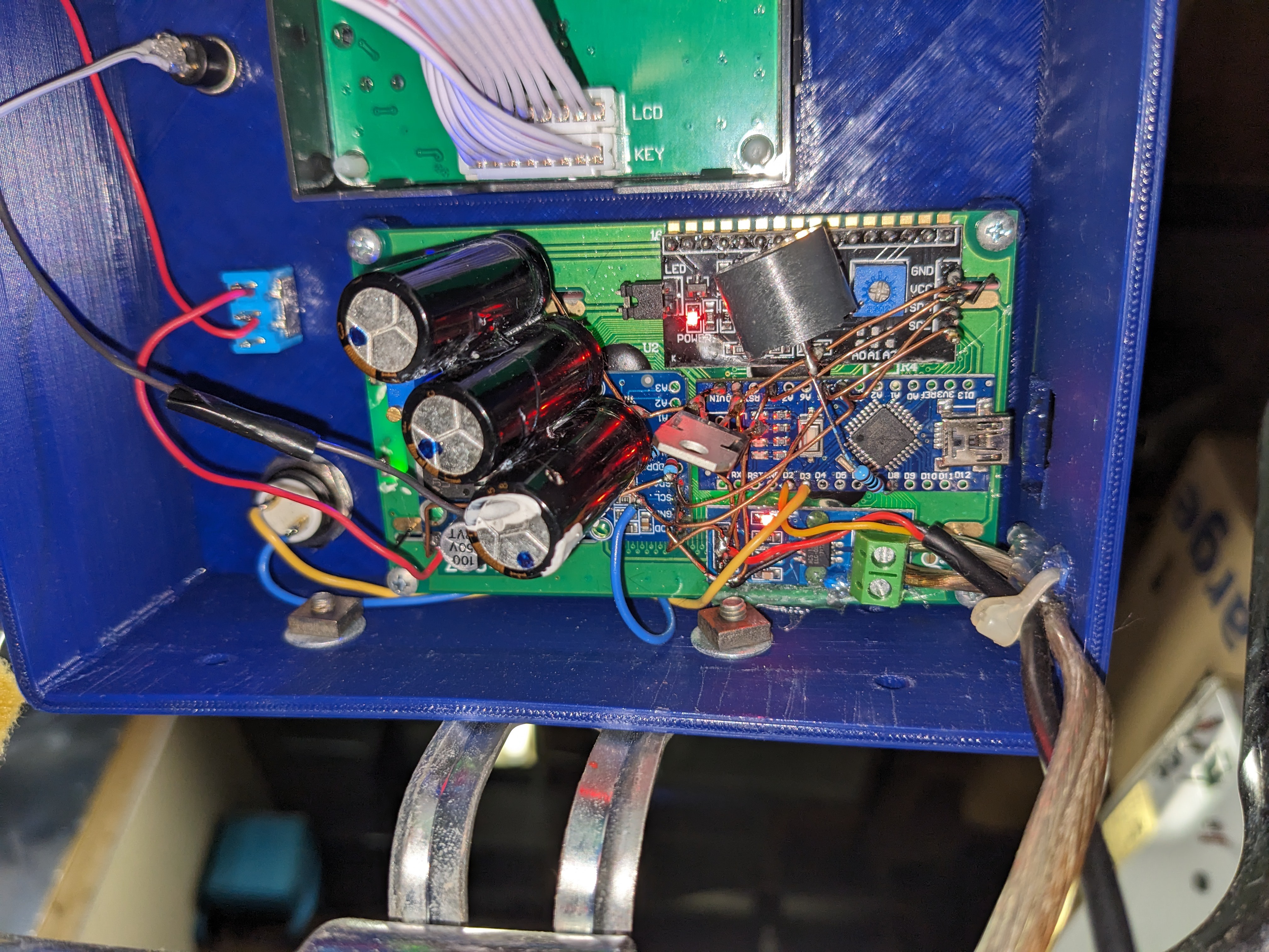
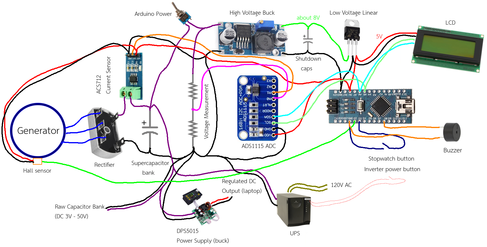
From the back, it's a messterpiece of solder and uninsulated wire (hey, as long as they don't touch, it's OK). To get a better idea, take a look at this crudely drawn schematic:
![]()
This is pretty much the entire electronics of the whole project. The rectifier and supercapacitor bank mentioned earlier are in there too, as are the previously discussed AC and DC power supplies for powering external devices. The whole thing runs on an Arduino Pro Mini, since we don't need anything too powerful.
The power is calculated from the instantaneous voltage and current. Voltage is measured with a regular voltage divider off the supercapacitor bank, and for the current, I measure it using one of those Hall effect current sensor modules. These a pretty neat; they pass a thick wire through the chip package, then measure the tiny magnetic field produced when current flows through a wire. This means that they have very low resistance, which means you do not lose power through your current meter. On the other hand, the magnetic field that they measure is so tiny, it is easily overpowered by nearby sources. In my own shop, they seemed to be affected by the earth's magnetic field. So they must be calibrated against some sort of current meter in the final setup so you can get an accurate reading in operation. The voltage divider is the same way, but is pretty much static once you figure out the scaling values to use. The sensor I used was for the 5A range, but I found that I can occasionally generate more than that when pedaling hard, which means my setup underestimates the total power a little bit sometimes, at the peaks when I push down a pedal.
Energy is of course the integral of power over time, which is done at a resolution of 40 Hz. This isn't super fast, but it's enough. The power is only measured as the output from the generator. Where it goes after that would probably be a good thing to know, so I may add a second current sensor. It is stored as an integer value internally so I don't need to worry about rounding.
I upgraded to a better ADC, since the one in the AVR is a bit low resolution, since I happened to have one.
For Arduino power, I used a cheap buck module with a very wide input range. I think most places state the max voltages of these at 37V, but I have been running the one in the bike up to 50 volts for well over a year, and it has not exploded or caught on fire yet. Don't recommend doing this, but there you go. The output from the buck supply goes into a linear regulator to provide a better quality 5V rail, so that I can run the ADC off it. BTW, the linear regulator does have the usual decoupling capacitors, I just didn't draw them.
Another feature is that the total energy is stored in EEPROM at a power loss, that way I don't have to track it manually. To allow this, I put a few scrap capacitors in the 1000uF range between the buck supply and linear regulator for the Arduino. When the measured voltage in the supercapacitor bank drops below 7 volts - the minimum dropout for the linear regulator - the Arduino knows it is about to lose power. This also happens if the power switch is flipped. The capacitors provide just enough juice for the Arduino to save the cumulative energy in the EEPROM before they run out.
There is also an RPM sensor which measures the generator RPM. This helps me get an idea of how the speed relates to the voltage, and besides, it was already there. Three hall effect sensors are internal to the motor housing, and I connected up one of them to get the RPM. These cannot be an encoder for the servo because they are far too low resolution; in my case, 2 pulses per turn. My guess is that maybe they are there to sense the initial magnet orientation at power up, so that the driver can start off at the correct phase, but I'm not completely sure.
The buzzer was included as a low power alarm for when I was running a laptop running at 20V. Once the supercapacitor bank dropped below about 19V, the alarm would start beeping, informing me that I needed to get back on the bike and resume pedaling. However, after some time I just found this annoying for those times I stepped away and forgot to turn off the Arduino power, so I eventually disabled it.
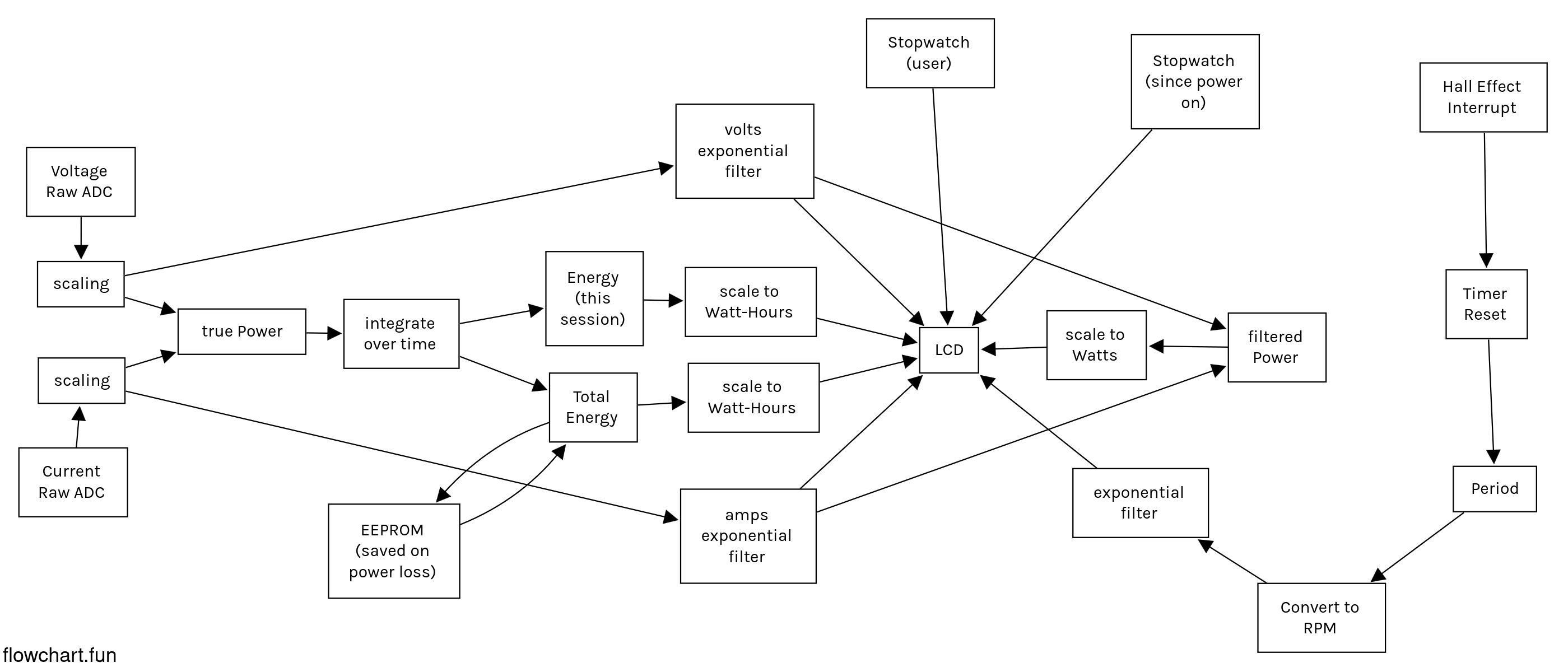
Finally, let's discuss what's actually running on the Arduino. Thanks to flowchart.fun, the diagram for this one is much neater.
![]()
Note that power is calculated two ways, once for the energy calculation, and once to show on the LCD. This is because the raw values are very noisy, and would probably just show on the LCD as blurry black squares of which you could only tell the first digit or two. However, you need unfiltered data to integrate properly.The power calculations and RPM meter take up 6 of the 8 spaces on the LCD, so I added 2 stopwatches. One is just a counter since the Arduino has been turned on, and the other is a user stopwatch, which I actually don't use that much. In addition, the since-power-on stopwatch only counts if the generator RPM is over some minimal value, that way you don't get time credit when the bicycle is stopped.
The last complication in the software is that the LCD is too slow to display the whole screen at once every 1/40th of a second, which is the loop time I use. To get around this, I just update one field per frame, and that has proven to work fine.
-
Power Supplies and Laptop
07/03/2023 at 23:52 • 0 commentsThe next part of the project is about the power supplies, which convert whatever I've got in the capacitor bank to the correct voltage for whatever device we want to power.
Technically, you can get by without one, at least for DC devices, just keep an eye on the capacitor voltage and be careful not to let your speed get higher than the voltage you want.
However, especially after the new chain retrofit, 12V, for example, is now too slow to pedal. Though it is true that it is the same energy rate, it is a far more comfortable experience to pedal at 30 or 40 volts and drop down to your target 12V using a buck regulator.50V, the maximum to which the capacitor bank can be charged, is also too low for a 120V device, even those that run well on DC. One way I could solve this is by buying more capacitors, then doubling the teeth on the jackshaft sprocket, which would spin the generator twice as fast and get into the 100-120V range easily. However, you'd still have to make some AC from that for some devices, and it now becomes more complicated to drop down again for low voltage DC devices. It seems 30-50V is a pretty good "middle ground" voltage from which you can go either up or down.
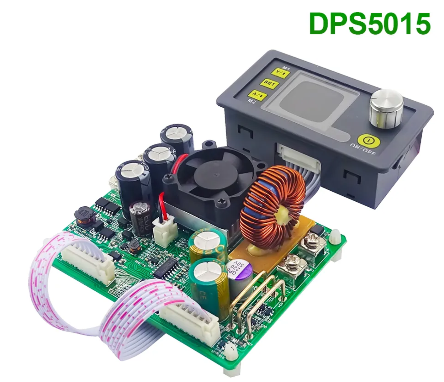
Let's start with the down part first. It's nothing special; buck regulators can be had any day of the week from the usual suppliers. I started out with a standard DPS5005, which is a small panel-mountable buck converter with a nice little screen and interface to set voltage and current limits. These are apparently a decent target for alternate firmwares which introduce better feature sets, but I have not had a need to try one out yet. Instead, after experiencing some dropout problems from the 5005 not being up to the task of handling power draw spikes from my laptop, I upgraded to the 15 amp version, the DPS5015.
![]()
This version maintains the panel-mount UI section, but the electronics are on an external board. Both devices are rated for 50V, or at least that's what it says on the box. I probably wouldn't use one of these in place of a lab bench supply, but if you just want to charge your phone, or maybe a battery, it's fine. That's got us the low voltage DC side covered, you can connect up whatever connector you need to the output terminals, set the voltage - maybe a current limit if you're feeling cautious, and you're off.
While we're here, I might as well talk about the laptop that I regularly power. It's a ThinkPad W530, also found in the trash. This was a pretty powerful laptop when it released in 2012, but over 10 years later it is still good enough to run Linux and browse the modern internet, and watch videos. As a powerful laptop, it had a high power adapter brick to go with it, which I didn't have, nor did I have any other Lenovo brick available. As it turns out, this uses what is known as a "slim tip" connector, which is sort of like a flat version of a normal barrel connector. It has contacts on the inside and outside surfaces which supply 20V; that pin in the middle is just so the laptop can tell what wattage of adapter is connected. Luckily, that's not some kind of anti-repair secret protocol, it's just a resistor between the middle pin and GND, 1K for a 135W charger. I decided to dispense with all of that, and, noticing that the connector was the approximate size of an XT30 connector, I replaced the whole connector with that (apologies - I seem to have lost the CAD for the mount I made for it).
![]()
Of course, the battery no longer held a charge either; about 40 minutes to an hour was all I could get out of it. I don't believe this laptop was particularly known for good battery life back in the day either. I used it with the battery for a while, until one day I dropped the battery on the ground and it broke (dumb). However, this was truly no major loss, and better aligns with my goal of "fully human powered", so I continued operating without the battery, powering directly through the charge port. Two things about this surprised me: that the laptop only required about 20-30 watts (which is easy enough to power without even thinking about it), and that that laptop would now operate way down at 12 volts, far below the 20V that the original brick used.
Something to consider is that deep down, all laptops are really 12V, because they all use 11.4V lithium ion batteries. Sometimes, you can even power them with a 12V source right off the battery terminals, with the battery removed, provided you can find the correct polarity. If you can't get it through the battery terminals, you can work your way through the power supply section until you find a spot to apply power. Arya Voronova's hackaday series is a good introduction to just what you can do with laptop motherboards. In my case, I just got lucky, and with no battery to charge, the rest of the laptop's circuitry was able to run off the reduced voltage.
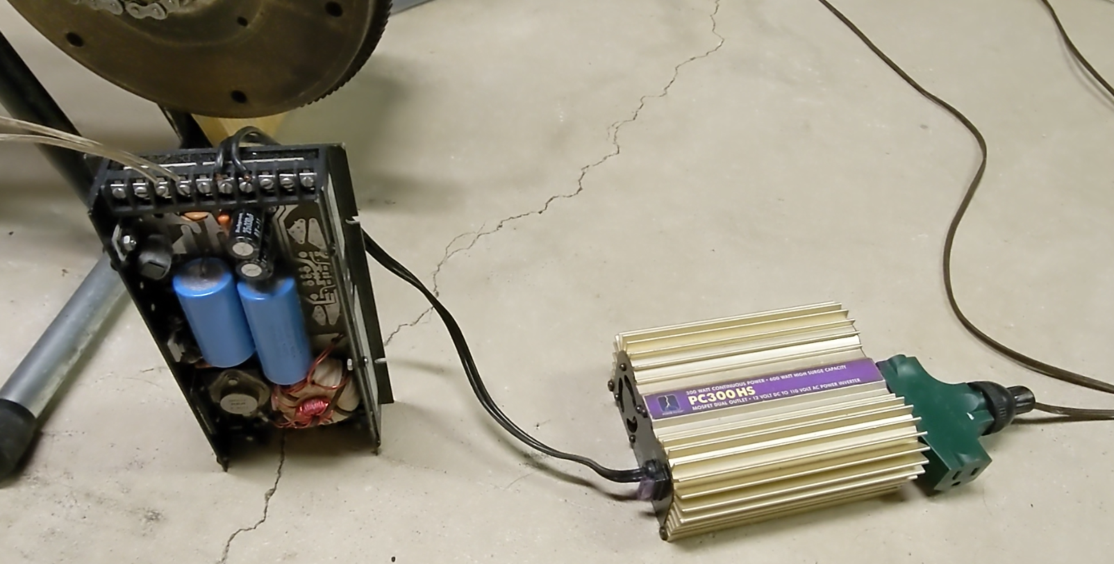
And now for the other half of the equation - powering 120V devices. Originally, I had nothing, until I scraped together a 50V to 12V converter, followed by a car inverter. If that sounds efficient, you should get your thermodynamics checked - it was not. In fact, you could barely power a 40 watt incandescent, and had no chance at powering a power brick for my regular laptop (not the one above).![]()
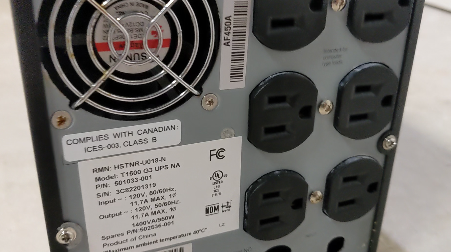
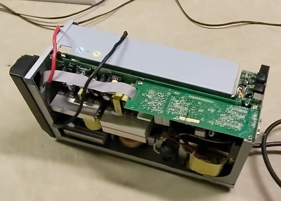
I was on the lookout for the sort of stuff the solar panel people use, although my own requirements were for far less power than those typically run. However, the same trash can blessed me with an upgrade once again. This time, it was a computer UPS. Now, I know that even you yourself have probably dug 10s of UPSs out of the trash over the years, but this one was special - it was somewhat better construction than the usual suspects, and seemed to be HP enterprise gear - a step up from the flat "power strip" kind you probably have under your desk at the office.
![]()
However, other than the claimed capacity of 1500 watts, I didn't find much useful information in the online manuals; this is clearly not from the same HP that once made the world's finest test equipment, not even the battery voltage was listed. The breakthrough came when I managed to find a listing for replacement batteries from a third party, which seemed to come as a set of 3 batteries. That seemed to suggest that this was a 36V unit, in the form of 3x 12V sealed lead acid cells.
![]()
The inside of the unit seemed to contain a lot of high quality components as well. I took the opportunity at this point to remove the power cord, since it was no longer needed. To the original battery connectors, I added an XT60 connector. I also added a smaller connector to the power on button - this unit had no problem being started on the "battery," so long as you held the power button in for a full second. That way, I could run the power button up to the bicycle handlebars, and power on and off the inverter as needed without needing to stop pedaling.
This particular trash find exceeded my expectations in 2 ways. First, I found that it had no problem working at 50V, all the way at full capacitor voltage. I suppose that when designing these sorts of things it isn't unreadable to over spec your components, but I was surprised that there was no over voltage lockout in this thing. There most certainly was low voltage lockout, and the unit would power off, and could not be started again, at 32V or lower.
I also found that the usual "on battery" alarm that sounds every few seconds on a normal UPS, could be disabled by pressing the included mute button. If I held the button in, that alarm would be silenced, but it would still allow the low voltage alarm to sound, providing some advance warning that it was time to recharge the capacitors. So, I simply soldered it closed.
![]()
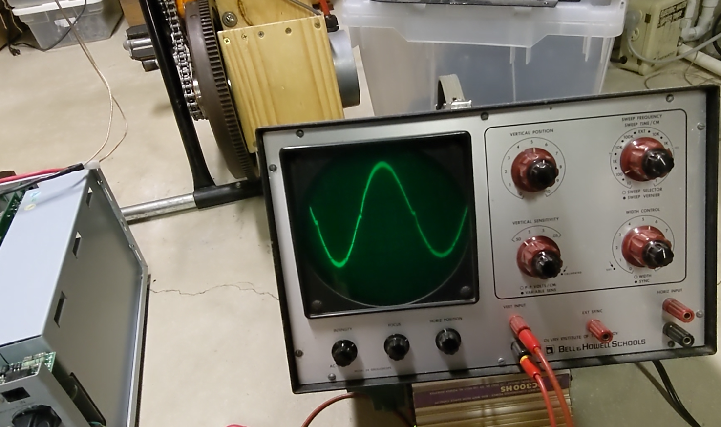
Second, it turned out to be a pure sine wave unit! It is easily able to power a small floor fan that I use to keep myself cool when operating the bike. For peak power, I found it could power 500W no problem, but 900W was too much; It could not power a normal toaster. That's beside the fact that I'd never be able to keep up with that sort of consumption in the first place. The rating is for 1500W, but I think I am experiencing some voltage drop in the wires I use to connect to the capacitors, or the capacitors themselves a much higher ESR that I expected. In any case, for my use case, it was fine, and surely overkill. -
The Toaster Challenge
07/02/2023 at 20:37 • 0 commentsStop me if you've seen this old viral video before:
Would you have guessed it was faked? By that I mean that the bicycle was not electrical, it was just a normal resistance bike. They generated an equivalent amount of mechanical power; they did not actually power the toaster, it was powered from the wall. Maybe I'm being too harsh, as nowhere in the description or video does it say that they are actually powering the toaster with the bicycle, but that's the impression I (and most of the comments under the video) get.
Here's another challenger doing the same thing in a more transparent way.
Since I have the equipment to do the challenge properly (although not the Olympic physique), I gave it a try. Thanks to the super-capacitors, I was able to maintain an average power of 100 watts, and managed to darken a bagel over 40 minutes. That one was good enough to make a proper video.
-
3D printing on pedal power
07/02/2023 at 19:51 • 0 commentsIf you hang around in the 3D printing community, you have no doubt seen the question of electrical power come up, which I have always found to be kind of an odd thing to think about. We don't think about the power used by a hot glue gun or soldering iron, do we? I suppose there are people who run their printers 24/7 or run print farms, though.
Anyhow, I decided to give it a go with one of my old printers on the bicycle.
It took the length of the print, but I was able to manage it. Hard though; it's also a bit higher power than I am used to running, I've only gone above 100 watt-hours per hour a few times. There's no way I'd have been able to do this with my Voron printer and its 650W rated bed. What if you had to pedal for it every time? Consider this the next time you print something.Alternatively, reassure yourself that in a coming global apocalypse, you'll still be able to make plastic boats, or if you prefer, more useful items. I should mention here that the laptop was also powered by the bicycle, though not the entire time. Once I switched on the heated bed, the 12V buck regulator was not able to power both the printer and laptop anymore.
It would be rude of me not to mention that this is not the first pedal powered 3D printer out there; that one was done as an art project by Pierre Clément Nivière back in 2016. As a result, it looks much nicer than mine, but looks a lot less comfortable and less optimized for a good pedaling speed. From the pictures, it also looks legitimate - I believe that it really powers the printer, unlike a certain toaster video. It printed a little statue though, so I might still be able to lay claim to the first #3DBenchy.
I did install the OS (Linux Mint) for the laptop and Prusaslicer under bicycle power though. With FreeCAD installed, I can have a fully human powered prototype facility. Although, in an apocalyptic scenario, you'd be hard pressed bootstrap any of that without internet access.
-
licensing
07/02/2023 at 03:41 • 0 commentsThe only code in my project is within the watt meter I built to help track my progress. It uses these components:
- Arduino AVR core (LGPL) - https://github.com/arduino/ArduinoCore-avr
- Adafruit ADS1X15 (BSD License) - https://github.com/adafruit/Adafruit_ADS1X15/blob/master/license.txt
- Adafruit BusIO (MIT) - https://github.com/adafruit/Adafruit_BusIO
- liquidcrystal_i2c (no license header; authors Frank de Brabander & Marco Schwartz) - https://github.com/johnrickman/LiquidCrystal_I2C
The above libraries are also available from the PlatformIO package manager, which is where I got them.
All remaining code (the stuff I have written), and CAD attached to this project is hereby released to the public domain.
-
Bicycle mounting
07/02/2023 at 00:28 • 0 commentsWhen building these things, everyone always seems to fall short on what I would consider to be the most important parts - the mechanical connection from the bicycle to the generator, and whatever gets used to keep the bicycle stationary. I've seen wobbly wooden frames, loose belts, and questionable friction wheels.
But, everyone has to start somewhere, and to better understand the generator performance, I first started by making a very basic pulley system.
The "bicycle" I selected for this project was an old Huffy stationary bicycle that had been sitting in the basement. Why we inherited this unit is unknown to me, since it's about as bare-bones as can be, and does a terrible job at regulating the resistance on the wheel (which is done by a (cheap) standard bicycle brake mechanism with a screw on it). The frame is very flimsy, and something you would never accept for a road bike. Even the cheapest stationary bicycle on Amazon seem luxurious by comparison. On the other hand, it was free, and after a modification to the seat to accommodate a very tall person like me, I thought it would be usable.
![]()
I didn't think of taking a picture of the original bike for some reason, so here's one I found online. It says "PRO" fitness, so you know it's legit. Interestingly, mine had a spoked wheel instead of the solid looking one shown here.
It did have a rubber "tire" though, and that's what I went for for a trial run. The wheel is quite flat, and would make a decent pulley if you could keep the belt from falling off the side. For the pulley on the generator, I went to the 3D printer. From the hand crank experiment, I knew that I wouldn't have to turn the generator very fast, so I printed out the biggest pulley that would fit on my bed.
![]()
Because the rubber tire on the bicycle would do a good enough job gripping it, I just used a piece of rope for the belt. That would not fly for the 3D printed pulley, so I cut out a section of inner tube and stretched it over it, to form a second "tire". Then, I could run the rope "belt" around the belt and wheel, and with an inverse clamp to push the motor and bicycle apart, it was enough to get things working.
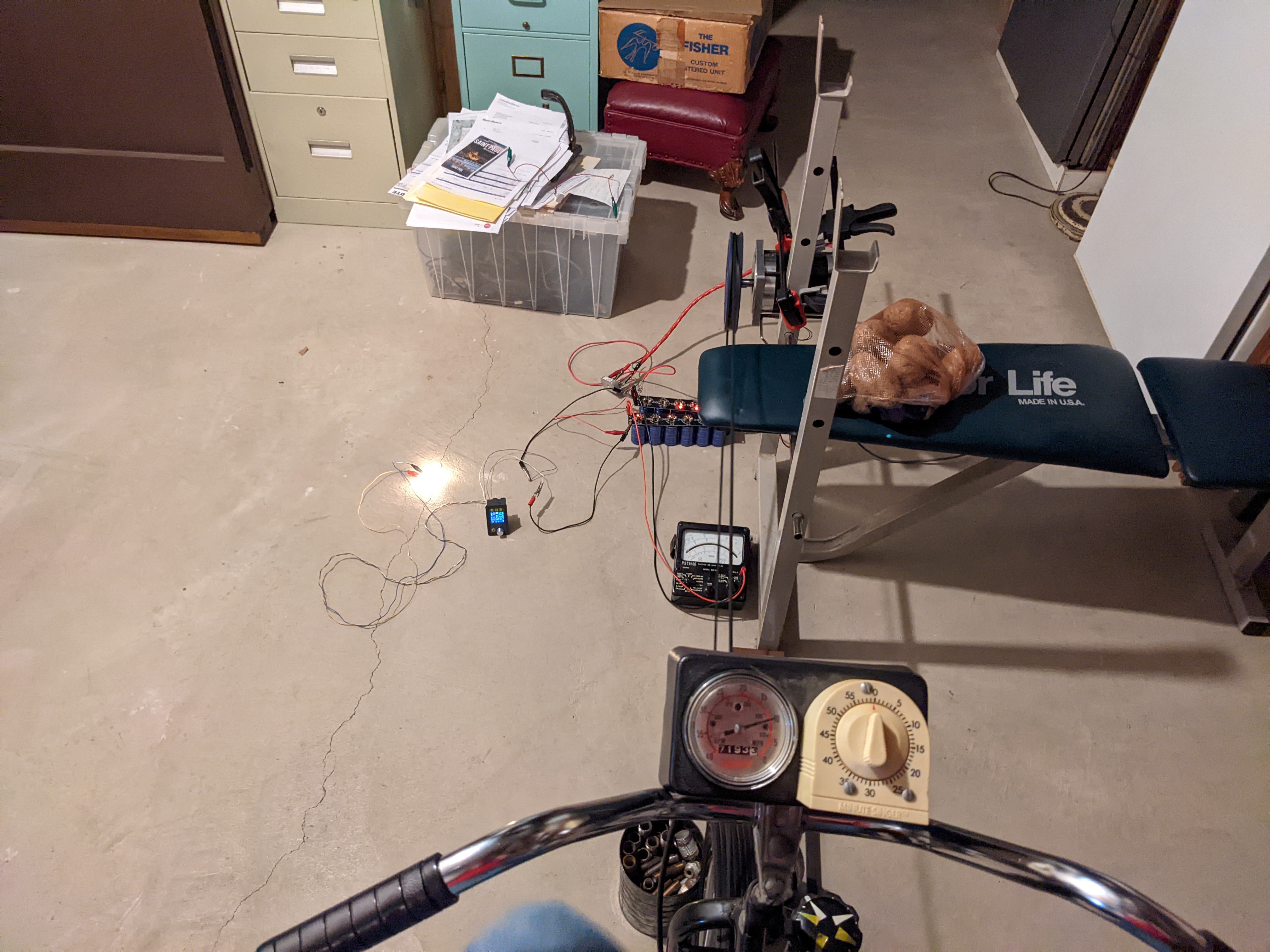
Here's the only picture I took of it, in January of 2022, complete with potatoes.
![]()
The coffee cans on the floor are filled with heavy metal scrap, and form the guides that help keep the belt on the bicycle wheel. As crude as this was, it did work, and I was able to power a light bulb for the fist time, before working my way up to a laptop. However, it had its problems - the belt would slip if not tensioned less than was need to lift the back of the bike off the ground, and it would also slip and fall off frequently, despite the guides. Above about 40-50 watts, it would slip and fall off, no matter what I tried. After a couple of months like this, I decided it was time for an upgrade, and I turned to EBay.
What I was looking for was a second roller chain set to replace the front wheel. As it turns out, I got the size of the generator pulley about right; 500 RPM was a pretty good target for the generator, and the generator-to-pedal ratio was about 6:1. The pedaling did seem a tiny bit fast, so I aimed for 7:1 in my redesign. Taking out the original bicycle chain setup, I could work out what ratio to look for. Not knowing the ins and outs of chain selection, I simply searched for kits that included both the chain and sprockets, so I could be sure they would all fit together. These seem to be sold as motorcycle and snowmobile replacement parts, so the chain I ended up getting was about twice as thick as the bicycle chain!
![]()
Incidentally, if you are looking for a decent introduction to chains for your own projects, I recommend Tim Hunkin's Secret Life of Components.
From here, I removed the front wheel and got to work on an intermediate shaft. I reused the existing ratcheting sprocket from the front wheel, which was threaded, so I got a chance to cut some threads on the lathe. Although threaded, the original manufacturers of the bicycle decided to weld the sprocket to the wheel for some reason, but a hacksaw soon isolated it.
![]()
I cut a keyway on the shaft with the mill, and then for the other sprocket, I just went for a 3D printed adapter. Although it is just PLA, and has developed some cracks, it has never let me down. After a few evenings of machining getting the shaft right, it sure does show why 3D printing is "rapid" prototyping!
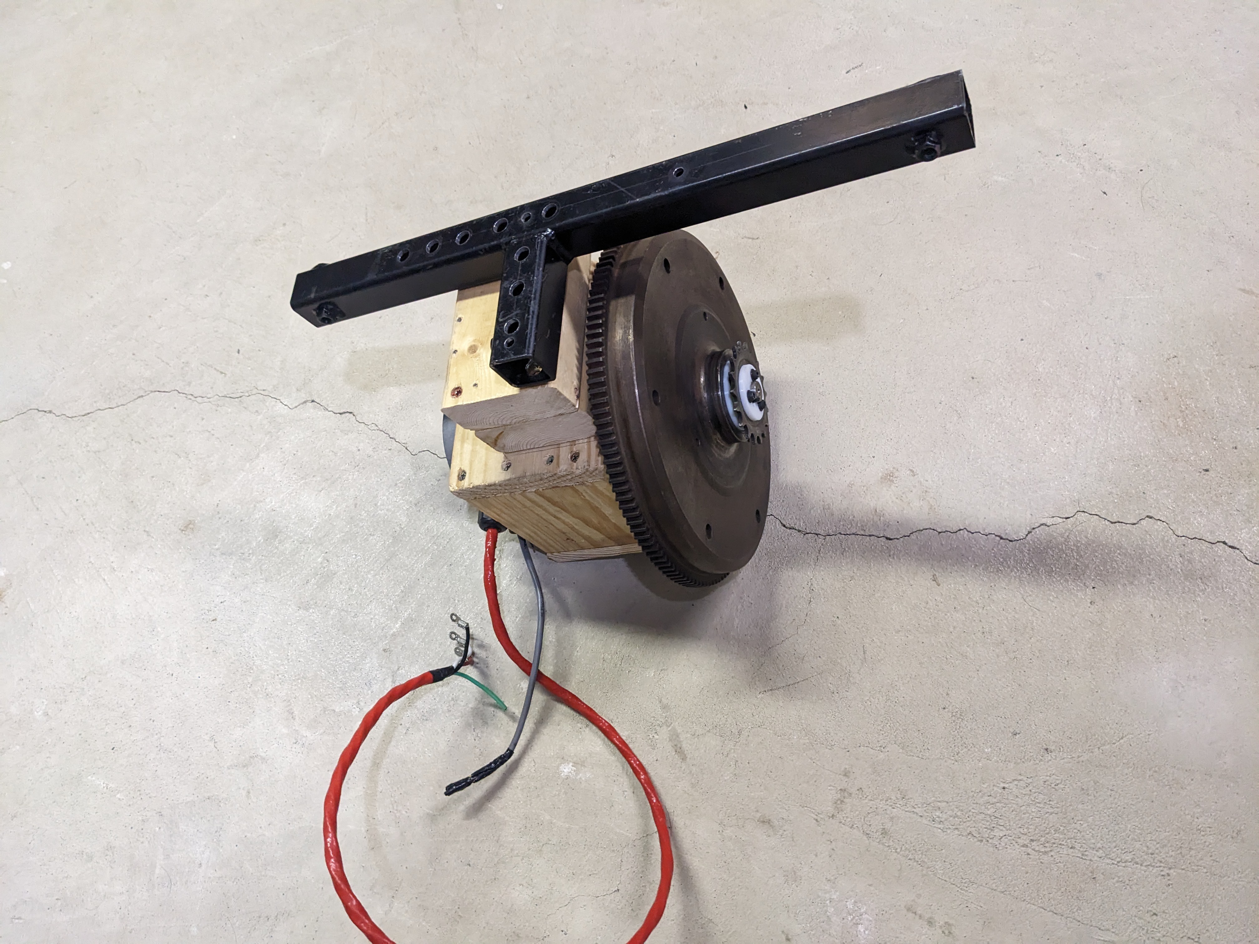
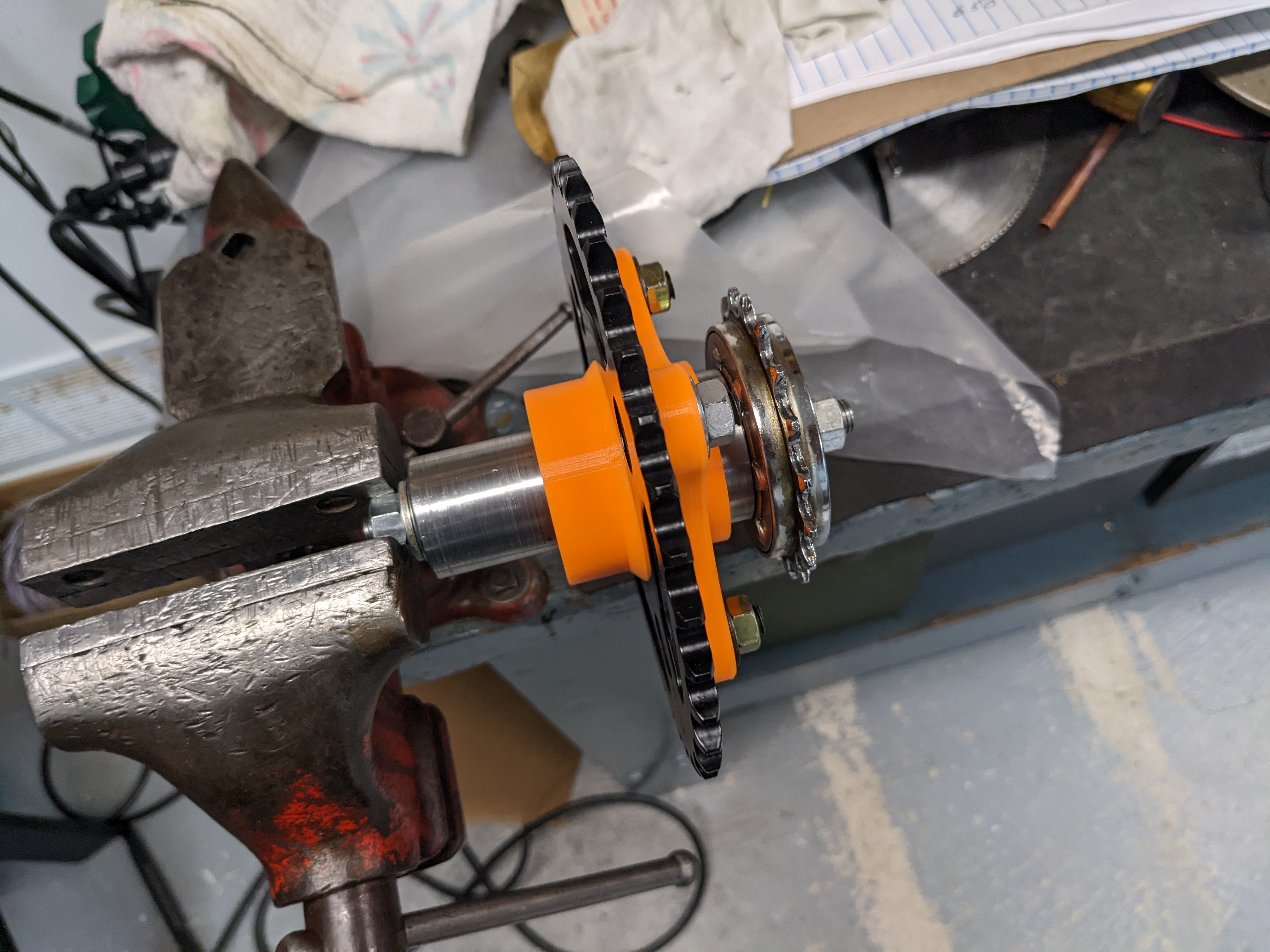
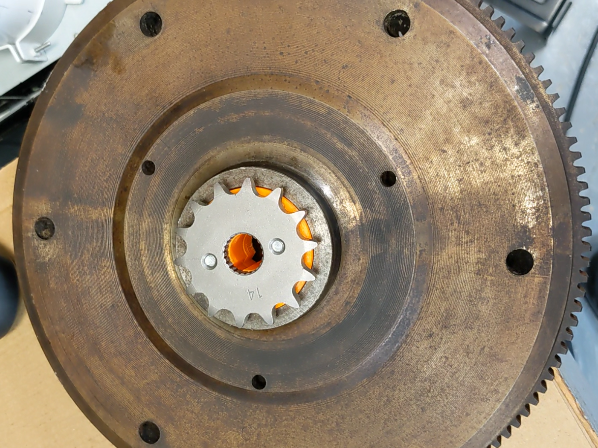
For the generator side, I enlarged the hole in the small sprocket, and made another 3D printed adapter. I also borrowed a spare VW beetle flywheel to throw on there, hoping it would help smooth things out, like momentum on a normal bicycle. I wasn't really sure if it would do anything, but when you have a stack of flywheels in the garage, it doesn't really hurt to try it anyway.
![]()
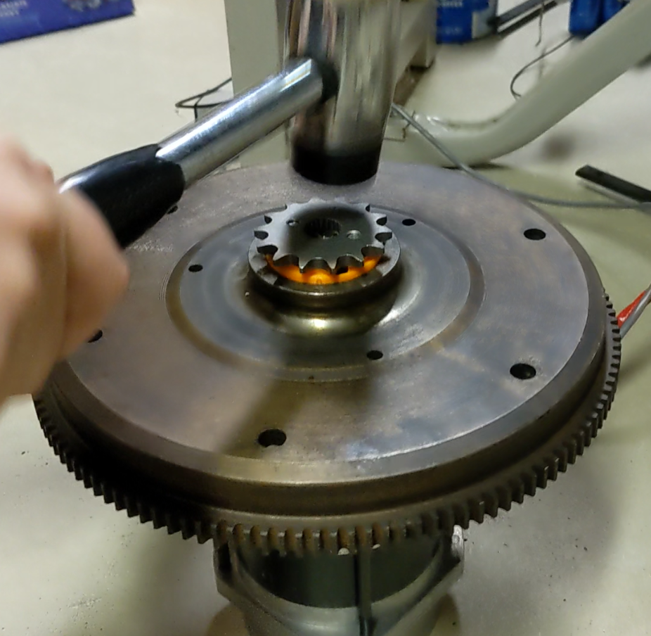
The assembly was then gingerly hammered into place for a press fit. Being PLA, I knew it had the potential to loosen over time, but after over a year, it seems to have pretty well stay put. Remember, everything in the powertrain here is rated for a fraction of its originally designed duty.
![]()
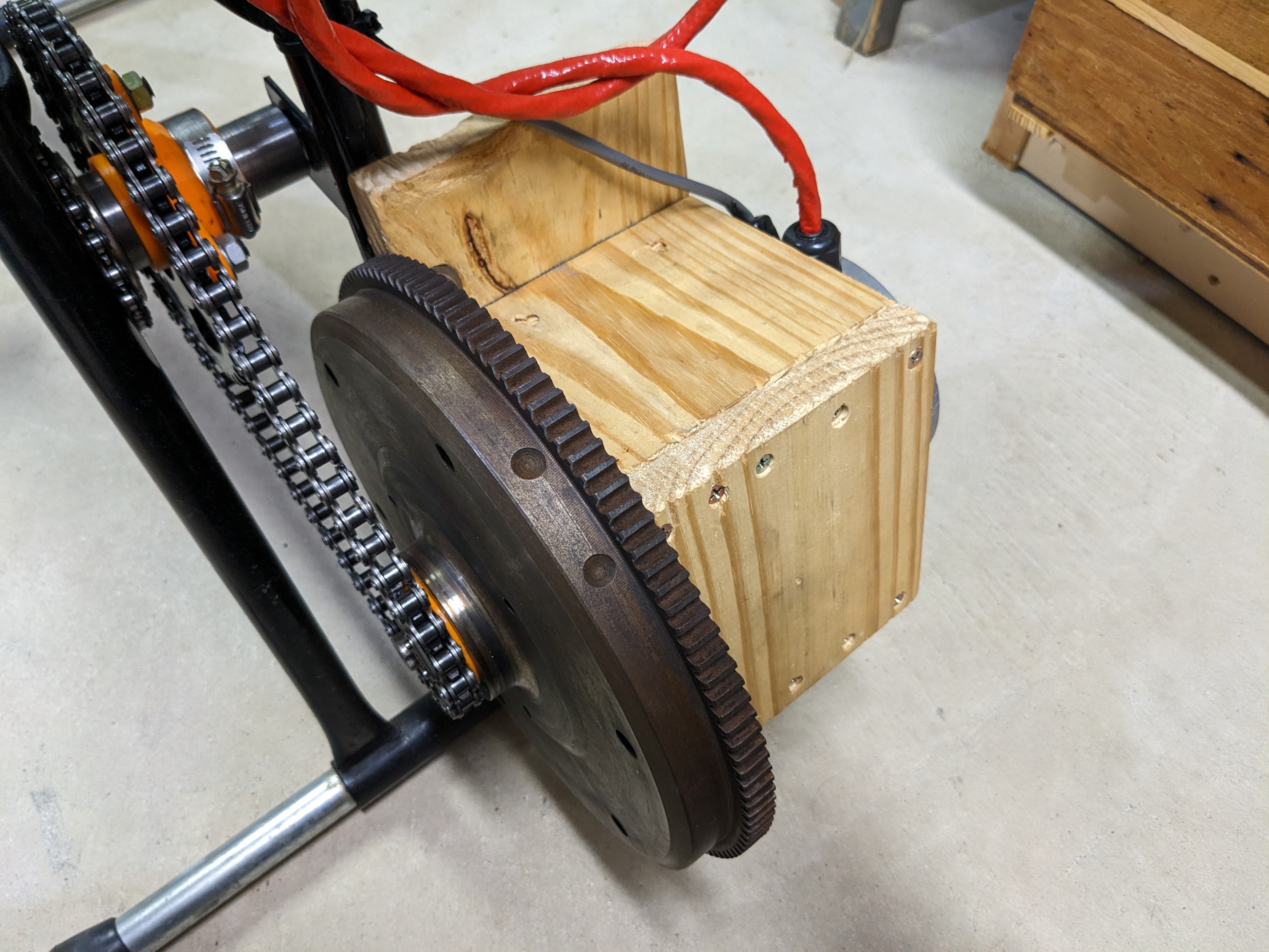
Next up, it was time to mount the generator to the bicycle. Because of the way I had to mount the sprocket, the original mounting face was now nearly covered by the flywheel bell. I decided to cut corners once again and simply decided to enclose the generator in a tight wooden box. The box is a tiny bit too small, and assembled around the motor housing with a bunch of screws, clamping it securely in place from all sides.
![]()
Three bolts through the frame of the bike mounts the assembly onto the bike, and washers behind it adjusts the chain tension. Although this mount does tend to flex a bit at the free corner, it's still a tremendous improvement over the old rope and pulleys, and I think it's reasonable that I would end up injuring myself in some way before I ever come close to damaging this setup.
-
Energy storage
07/01/2023 at 04:11 • 0 commentsThe thing about generators is that when they stop turning, they stop working. If you are powering a laptop with no battery, such as the kind I often find in the trash, it means that if you stop pedaling for even a moment, your laptop will die.
Also, I don't know if you have ever pedaled anything before, but the power comes in pulses from each leg. A light bulb would be rather flickery if powered directly from the generator, unless you are very careful to pedal smooth enough so that the generator is always at a constant speed.
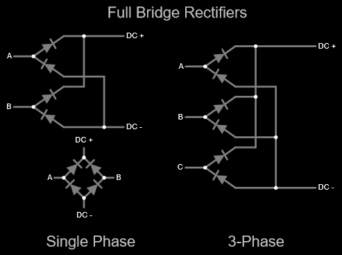
Also, the output of the generator is 3 phase AC. While it is fine to put a light bulb across two of the phases and use it like that, we are missing out on some of the generating capacity that way. Most of the stuff I want to power does not use 3-phase AC anyways, so first let's convert it using everyone's favorite diode arrangement, the full bridge rectifier.
If you have never come across the 3 phase version before, it's just like a single phase version, just with 2 extra diodes.![]()
You put a pair of diodes on each phase. One of the diodes captures the positive side of the waveform, and the other one captures the negative side. Collect the negatives and positives, and you've got DC.
These are available in pre-made packages just like the square 4 terminal power rectifiers you can find, these just have 5 terminals - 2 for the DC output and 3 for the 3 phases. I bought a few off the usual suspects.
![]()
The ratings on these might be a bit dubious, but should be well within the comparatively measly power we could ever hope to get out of a bicycle.We have DC now, but what about storage? I could use batteries; just connect one directly to the output of the rectifier, but it rather violates my rule about having non-human power. Batteries, of any kind, must be maintained above some minimum voltage. Drain one to zero volts, and it is likely to damage the cell. But, having a measurable voltage present at all times sure feels like there is non-human power included on board, even if the usable energy available in a "discharged" battery is small.
Also, batteries don't have all that much voltage range available, meaning that we would have to get the generator up to a certain minimum speed just to be able to charge one, and could not go too fast or risk overcharging it.
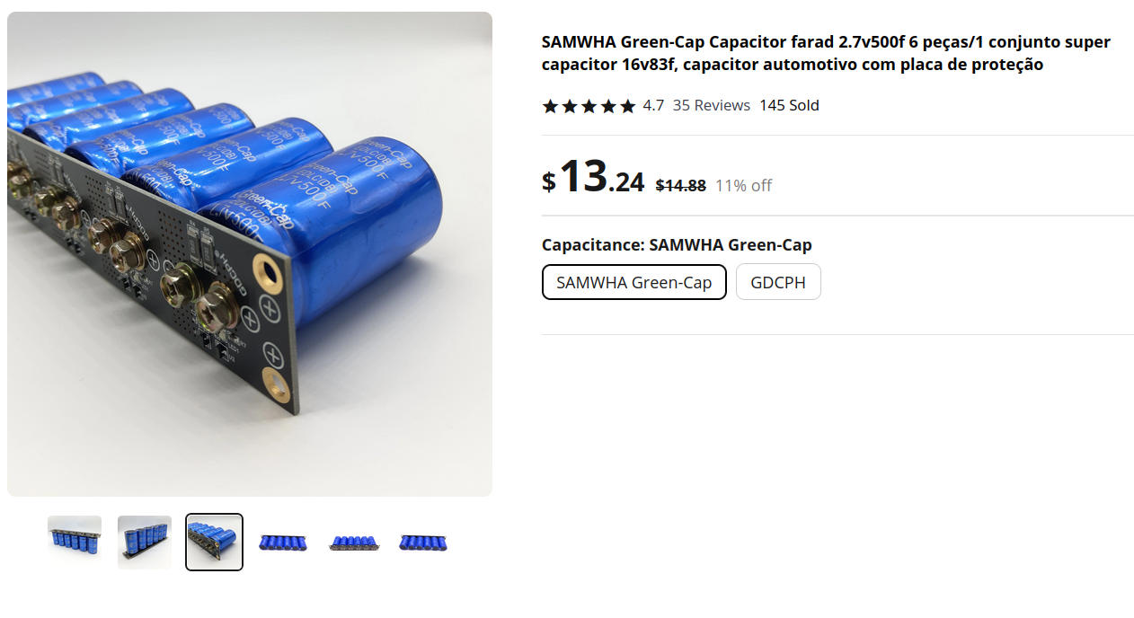
Instead, I decided to look into supercapacitors, which wouldn't you know it, are also available from Aliexpress.
![]()
These are 6x 500F capacitors in series, each with its own discharge circuit built in, which activates if the capacitor voltage gets too high. Supercapacitors are generally only rated for a few volts, in this case, 2.7. The overvoltage protection is not too strong though, taking 10s of seconds after coming on to drain the capacitor voltage back within spec.
Capacitors can be drained all the way to zero, and operate at any voltage (meaning arbitrary generator speed) up to their spec. They can also accept and dump lots of current; both of these features make for an ideal choice for this project.
I started out with 2 of these prebuilt units, but eventually upgraded to 3 after I realized my preferred cycling speed put the generator voltage above the limit for just 2 units.
So that's 18 capacitors in series, for a total of about 27 farads of capacitance at up to 48 volts. We can use the regular capacitance formula to find that, at full charge (48 volts), a capacitor bank of this size will hold about 31 kilojoules. That's about 8.5 watt-hours, so we can power something that is 8.5 watts, for an hour.
How much is that? Well, a single AA battery contains around 2-3 watt-hours, so our whole capacitor bank, when full, contains roughly 3 AAs worth of energy. That doesn't sound like much, but in potential energy terms that's enough power to lift a 1kg weight nearly 1.9 miles into the air!
Compared to the typical laptop battery, which might be around 50 watt hours, it's enough to stop pedaling and keep our laptop running for 10s of minutes. I feel like this is a pretty good time resolution for this project - it's not so little storage that all we can handle is a few seconds, but not so high that we might spend several hours or even days charging up a massive sealed lead acid battery, which can hold hundreds of watt-hours. It should add a much more human timescale to this project.
Practical Power Cycling
Sustainable* electricity you make yourself! *for as long as you're willing to sustain.