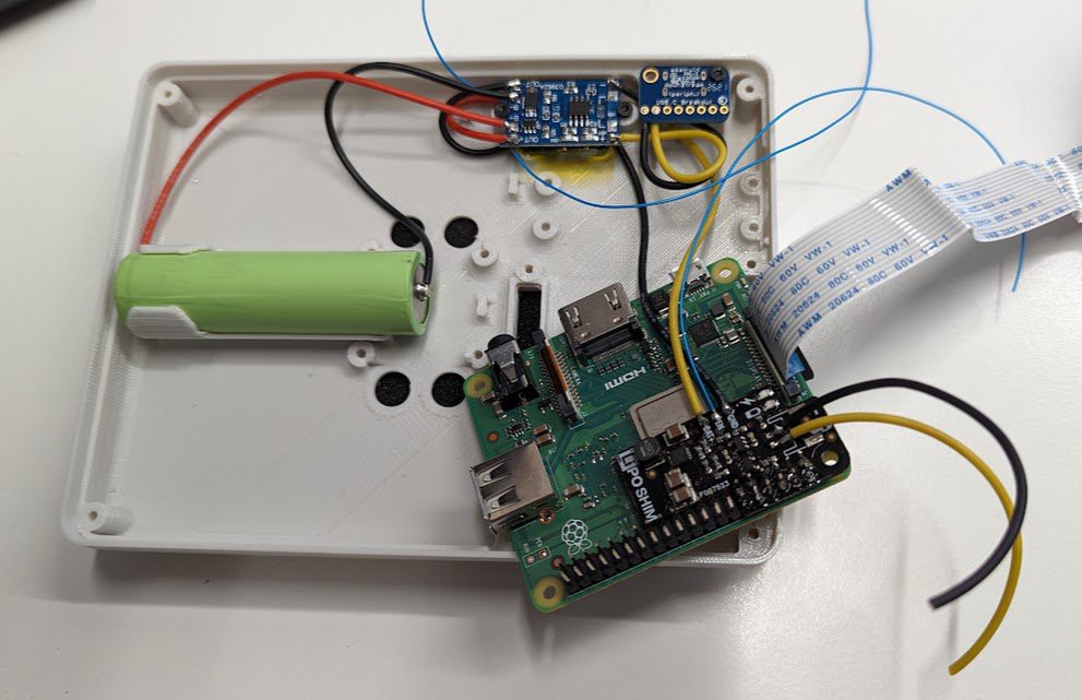
Solid progress. I re-made the back 5-way switches with diodes the other way around. My first draft will get used in some other project another time. And all input devices are wired up and working now!
And the power stuff is all soldered up now:
- USB to charge board is black and yellow.
- Battery to charge board, and charge board to the main power switch are black and red.
- Power switch to the pimoroni lipo boost shim is black and yellow,
- And I left a black and yellow pair hanging off the shim to power the pi pico at un-boosted lopo voltage.
- The fine blue wires are:
- v+ from the switch directly to a resistor bridge to the pico analog pin for battery monitoring.
- off pin from the switch to the pico to turn power off completely to everything
- enable pin from the lipo shim so the pico can cut power to the pi 3a+ board.

I would be doing final assembly but I goofed up the last print.. So I'll hopefully put it all together and not have unexpected issues with fit this weekend!
Aaaand a note about soldering to 18650 cells - I don't recommend it, but if you do, use flux and a hot iron. Get a blob of solder on each end of the cell, clean up the flux with alcohol, and let it cool. Tin your wires. Then go back and solder the wires into the blobs, working fast so you don't put much heat into the cell. It's better to spot weld or maybe use a battery holder.
And on this theme of doing responsible things, I will go back and add an axial fuse to my battery lead. It's a good idea for safety.
 Dan (a8ksh4)
Discussions
Become a Hackaday.io Member
Create an account to leave a comment. Already have an account? Log In.