 make2xplore
-
1All Instructions
Project scenario - With Components
Project scenario - With Components Here is the pictorial representation of the project assembly. There will be a Transmitter and Receiver sections.
- In transmitter part, we will connect Node MCU ESP8266, to LoRa Module RYLR998 through serial interfacing.
- And On receiver side, another ESP8266 is connected with Reyax LoRa module. Which will act as a LoRa Receiver or Gateway.
- Here transmitter side sends these environmental parameters readings to receiver through LoRa. At regular interval of time.
- The receiver or Gateway receives those readings and upload it to cloud. Which then can be accessed by farmer from his cellphone or PC. So he can monitor the greenhouse.
- Also, at greenhouse, we will implement some basic level automation for irrigation system. Therefore, As soon as soil moisture level falls below certain level, Water pump will get start, and, It will circulate water to the plants.
- All this communication of LoRa, can be achieved using LoRa transceiver Module RYLR998.
Project - Functional Block Diagram -
2Hardware -1
Hardware overview -
Getting started with RYLR998 module. This module is a UART Interface enabled 868/915 MHz LoRa, with Antenna Transceiver module. You can know more about this module and download the datasheets from its Product Page.
How to configure/Program -
There are two main ways to utilize the RYLR998 module.
- First is, interfacing it with USB to Serial TTL adapter module, then connect it to PC via USB and control by AT commands. You can use any serial communication software to send AT commands and read data from the boards.
- Then second method is connecting RYLR998 to another mainboard via UART and control by AT commands. For example, connect RYLR998 to Arduino Uno via UART, and send AT commands and read data from Arduino Uno through Arduino IDE’s serial monitor.
You can refer AT commands Guide given by Reyax for more details about command sequence to configure this LoRa module.
This document of AT commands Guide also have detailed explanation of each command. Like following SEND command, used to send the data from transmitter to receiver
In above sequence of using AT Commands, Network ID is important command, which Set the network ID for the given device. As we seen earlier that we are going to program our Project in P2P LoRa networking mode. For that we have to set same Network ID of both [Transmitter and Receiver(Gateway) device]. Please refer following figure for more details
You can see here, in this diagram. There are two different LoRa networks. Network 1, and, Network 2.
- Each node in Network should have unique Address.
- Nodes with same Network ID’s, can talk to each other.
- Also, Lora frequency band should be correct, as per standard frequency for respective country, or region.
-
3Hardware-2
- Here, please note that, you have to set the Lora frequency or band, as per your country and region. As we are testing it in India, we have set it as Standard IN865 band. likewise, you have to set it as per your countries LoRa Standard allocated by LoRa Alliance.
- **Here, very IMP, note that, Nodes from different networks, means, with different Network ID’s, can not communicate with each other.
- So, In this project, we have configured both transmitter and receiver with same frequency band, same Network ID, and, different addresses.
- Therefore, we can say, for proper LoRa communication between two nodes, LoRa trans receiver device should be configured with these three parameters. As shown in above image. i.e. Band, Network ID and, Device Address on Network.
- Hence in Code, Before starting communication between two LoRa nodes, we need to run specificsequence of commandsto configure RYLR998 Module in LoRa Transmitter and LoRa Receiver Modes.
- Then at receiver, you have to run +RCV command if you want to show the receive data actively on terminal window. (Optional step)
- You can use.readString(); to save the received data into string variable, like shown in code snippet of receiver node, as following
-
4Software -1
Software :
We have shared transmitter and receiver code. You can also check out project's GitHub repository for all the documentation, (Circuit diagrams, Schematics, Datasheets, AT Command's Guide, Libraries and Source codes.)
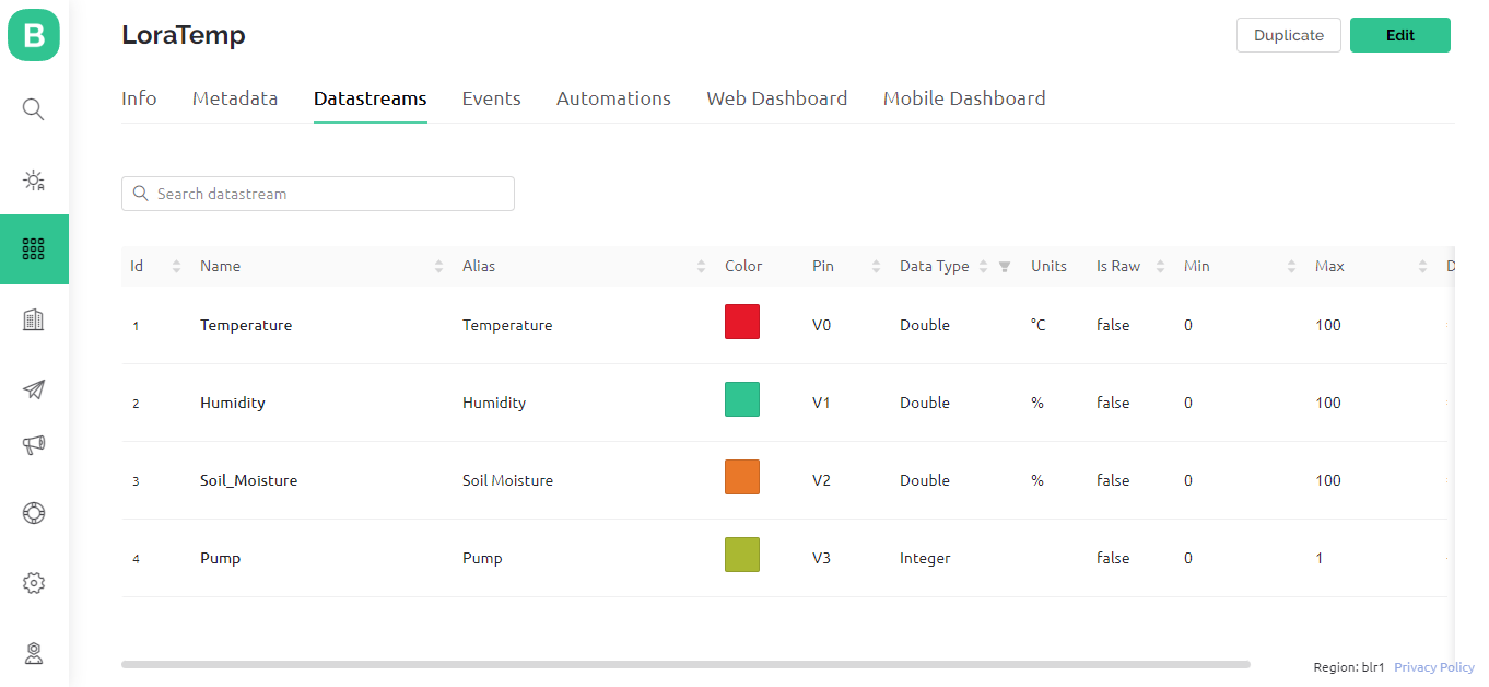
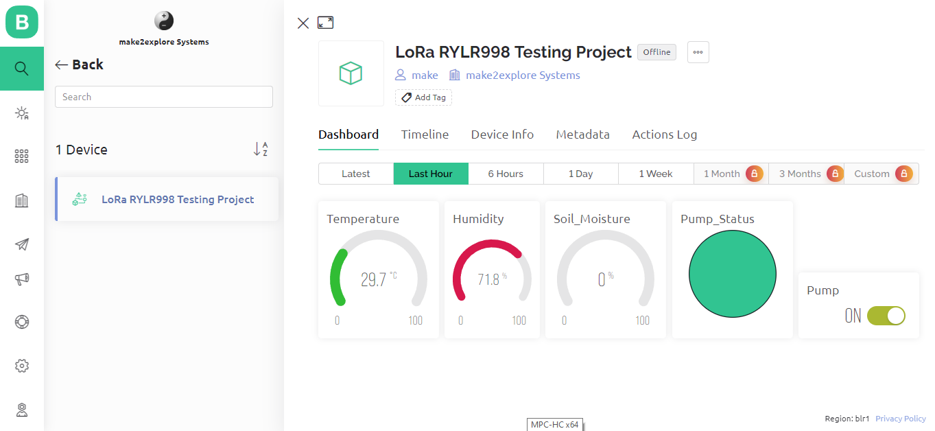
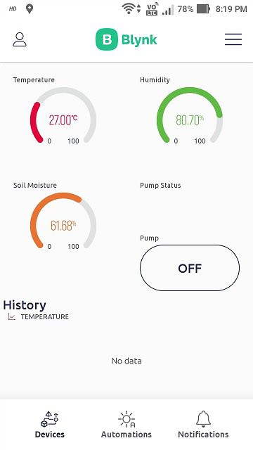
We are going to use Blynk IoT Platform for monitoring Greenhouse data. Blynk was designed for the Internet of Things. It can control hardware remotely, it can display sensor data, it can store data, visualize it and do many other cool things.
![]()
![]()
![]()
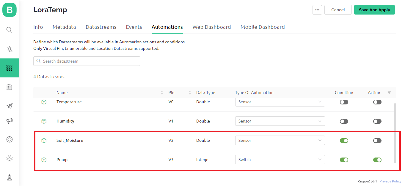
We have also added simple edge level automation which we have programmed for irrigation system. In this automation, if soil moisture level falls below 40 percent, Water pump will get start. And it will provide water to the plants until soil moisture level rises above 60 percent. We can also use automation and notification alerts facility of Blynk app.
![]()
Greenhouse Monitoring System - LoRa IoT
Monitoring parameters of Greenhouse located at remote location (with no Internet Connectivity), using LoRa IoT


Discussions
Become a Hackaday.io Member
Create an account to leave a comment. Already have an account? Log In.