-
1Main chassis Fabrication
Print the main chassis in as few parts as possible with a maximum infill, to ensure structual strength.
I printed mine on an Anycubic Mega X and was was able to print it in only 2 sections and used epoxy glue to secure the parts toghter. -
2Install the threaded inserts
Around the open top of the case are a series of holes in which to install the threaded inserts.
Position the threaded insert above the hole, with a pair of pliers, then insert the tip of a soldering iron into the threaded insert. Gently press down until the insert is flush with the casing.
Repeat for all the holes around the open side of the case.
-
3Install power port
Attach the USB-C extention cable to the provided mounting point in the end cap, on the left side.
This will connect to the PiJiuce module to act as the power port
-
4Install power switch
The power switch is mounted in the handle well, in top right coner of the case.
This will connect to the relivant pins on the PiJiuce module.
-
5Install KM swicth
The bi-directional USB switch is mounted vertically in the provided spot in the handle well., next to the power switch
-
6Install SDR module
The NESDR Nano 3 SDR can be secured inthe recessed area on the inside of the case with an adesive pad.
A hole is provided in the end-cap to allow for an anntena to be attached.
-
7Install the SBC and power
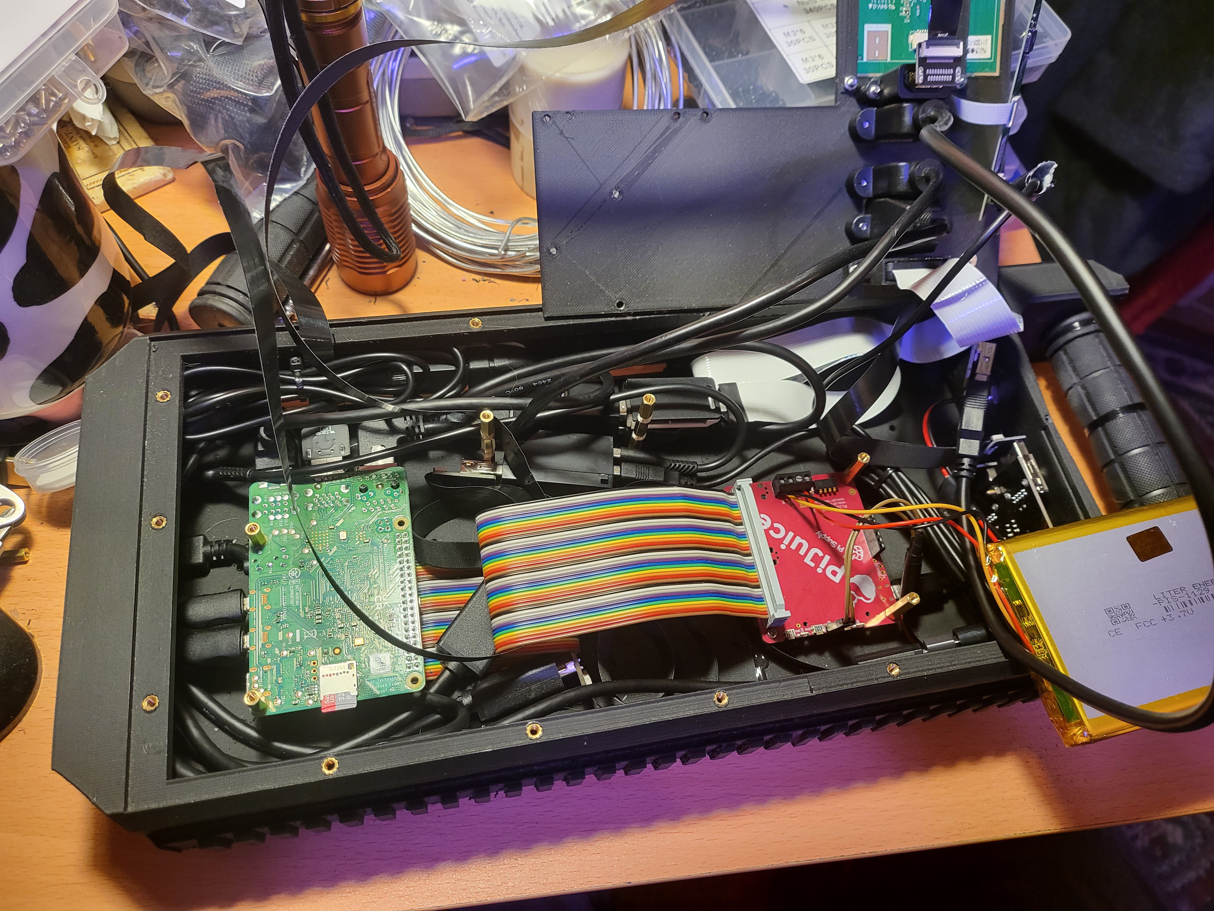
Use the standoffs to secure the Raspbreey Pi board on the left side of the case and PiJuice power module on the right, leaving space between them for the battery and room on the handle end for the top/front I/O to fit.
Bridge the RPi's GPIO to the PiJiuce's with a 40-pin ribbon cable.
-
8Attach the cables
Cables can now be run around the edges of the case, in the recessed runs provided.
- The USB-C power port should be connected to the PiJuice.
- Connect the cables for both the keyboard and trackpad to a 2-port USB hub, and connect the hub to the single-port side of the KM switch. THen run one of teh switch's outputs to the Raspberry Pi, and the other to the USB extention that will be mounted in the top panel.
- Connect the SDR to the RPi by USB cable
- The rest of the top-panel I/O should be connected to their respective ports on the RPi at this stage.
- One HDMI and one Micro-USB cable should also be connected for the screen.
![]()
-
9Keyboard support
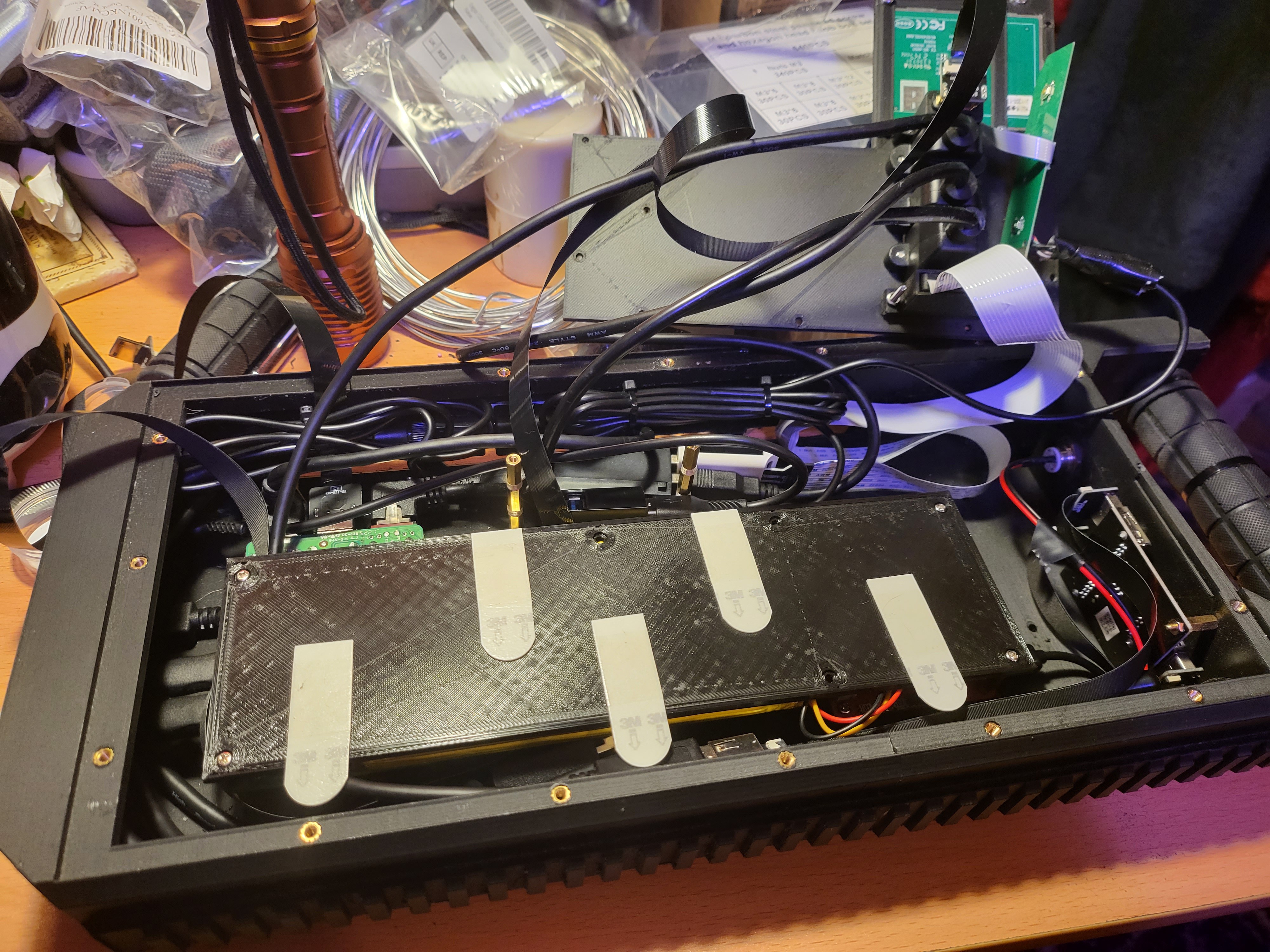
Attach aditional stand-offs above the Raspbreey Pi and PiJuice.
A small internal shelf then screws on over the mainbaord and power management board. It holds the battery and some cables in place and also gives the keyboard a solid platform to rest on.I initially used the adhesive strips (as you can see bellow) to keep the keyboard in place, but the top pannel fit together snugly enough that they ended up being unnessessary, but provide some extra security.
![]()
-
10Top Pannel
As with the main chassis, the top plate be printed in as few parts as possible.
The plate attaches with M3 screws around the edge of the case, with holes to feed the screen cables through. and places to mount the front facing I/O.
There are also pre-set hole for the U-shaped handles to be attched.
 Garra
Garra

Discussions
Become a Hackaday.io Member
Create an account to leave a comment. Already have an account? Log In.