Lighting Concept
The development process of Circadian started with a lot of research considering melatonin, the circadian rhythm and light therapy and was followed by picking the LEDs. I decided for Osram's Oslon SSL series because of its high CRI (95) white and broad color variety. 12 neutral white LEDs provide 2100lm during the day and 2 yellow, 2 amber, 2 red and 2 hyper red LEDs emit an enchanting orange light at up to 1100lm. The LEDs are split up in two white strings and one orange string at 18V each.
In contrast to commercially available lamps, Circadian does not use a warm white LED for its evening mode, because even warm white has a lot of blue spectrum. Light containing only wavelength above 530nm does not suppress the production of melatonin and amber being the bluest of the LEDs I used lays in safe distance to this threshold. Another conclusion of my research was, that I should use the white light at full power in the morning to increase my serotonin level.
Design
After the emitters were chosen, I could start working on the appearance of the lamp. I decided for a minimalistic design, which seems to be held together by a continuous brushed aluminium rod. The rod is actually a 12mm tube press fit into the upper heat sink and then two screwable aluminium pieces attaching the diffusor plate to the lower heat sink. The raw brushed finish was achived by filing the turning parts.
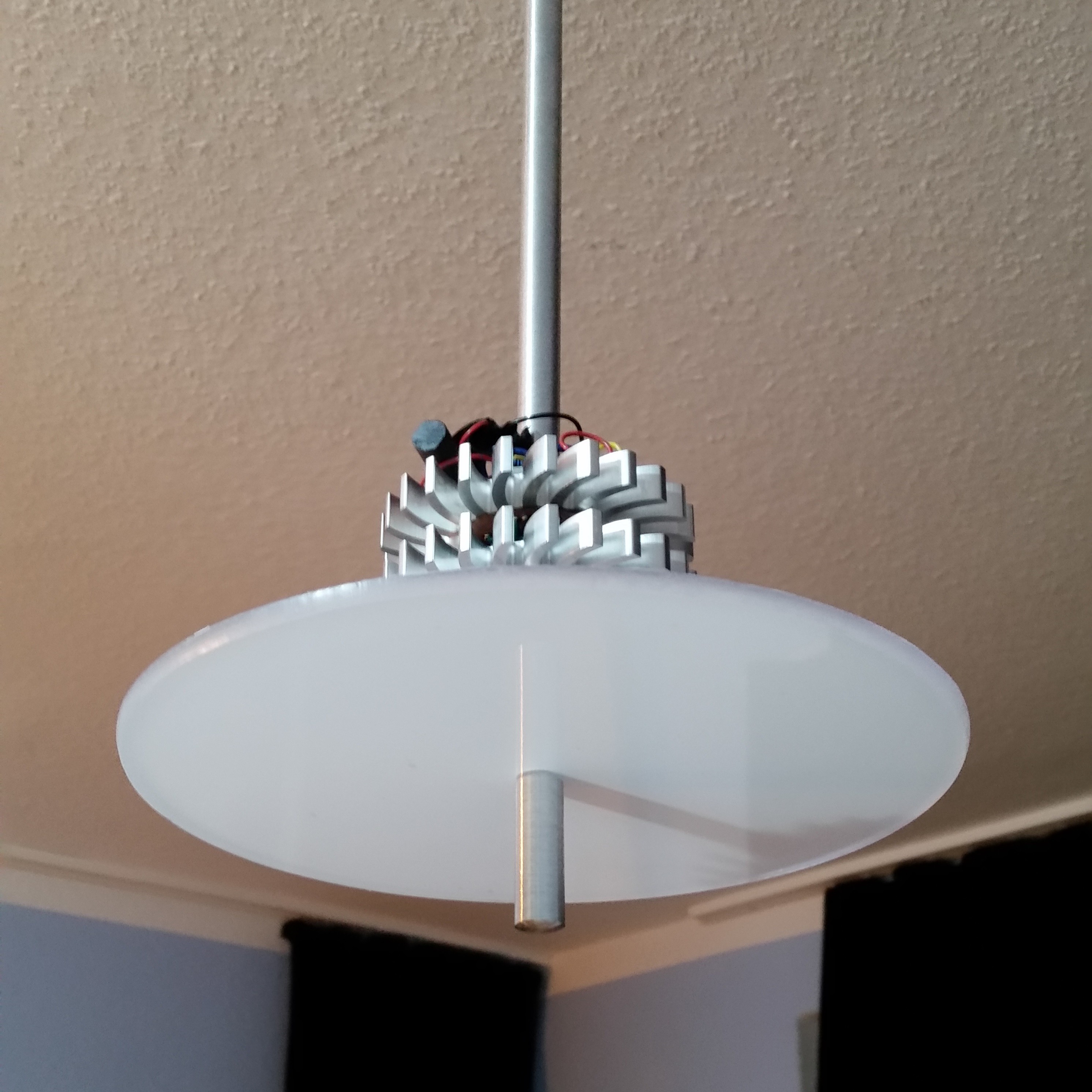
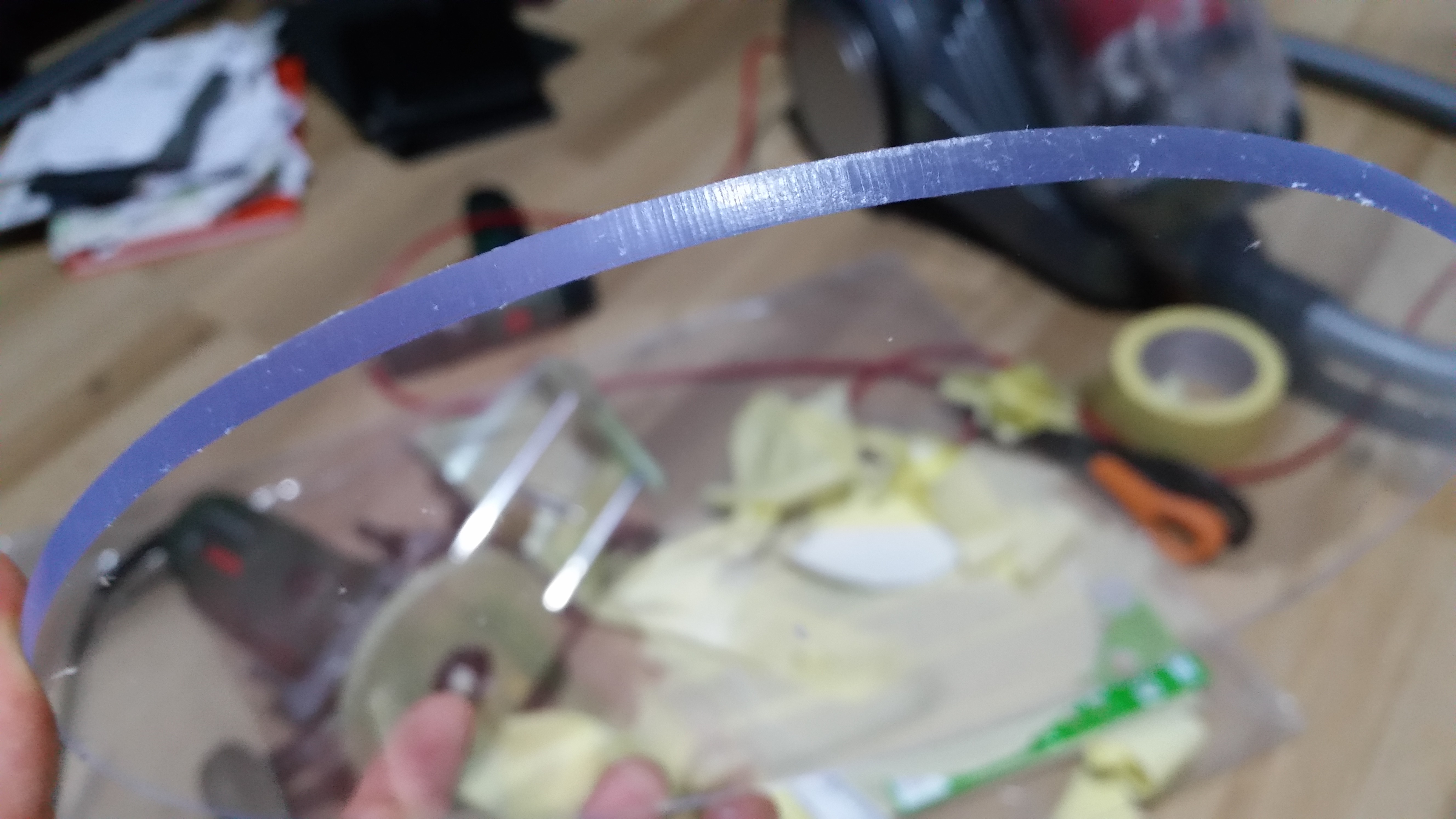
The diffusor plate was milled from 4mm acrylic sheet using a router and lots of protective masking tape. I cleaned up the edge with a 9mm radius head dropped to about the middle, resulting in a nicely rounded edge and a slightly bigger top side, which hides the upper edge from people looking at the lamp from below. Instead of sanding it to achive a matte finish, I covered the plate with some back projection foil. The foil diffuses the light perfectly in all directions and absorbs just a small fraction of the LEDs' light. If you should plan on making a lamp or something that needs to diffuse LED light, I can only recommend this technique. You don't have to buy a whole roll. I ordered an A4 sample piece for less than 2 bucks online.
Thermal Management
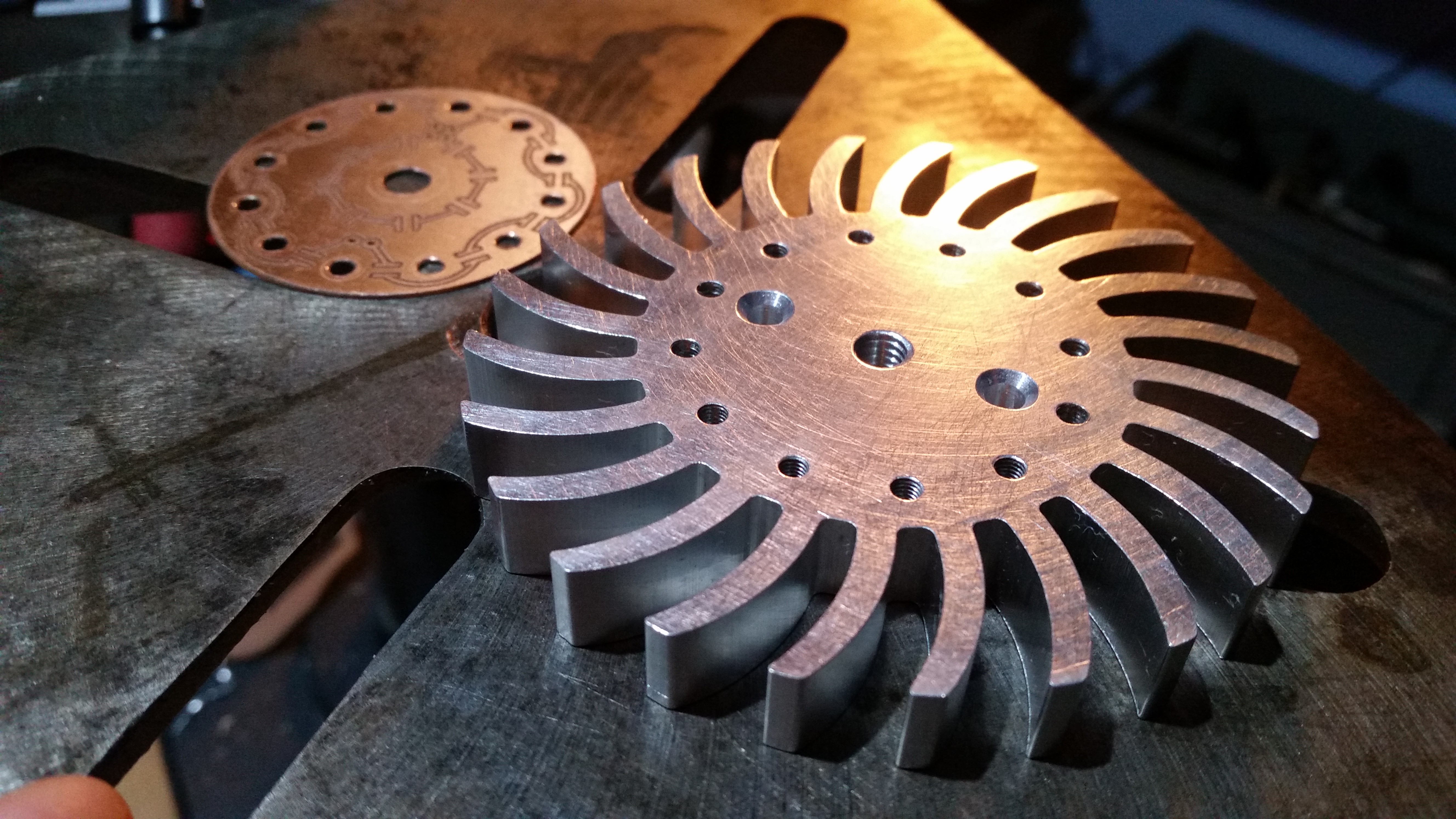
The LEDs' waste energy is transported through their board's .5mm FR4, M3 brass screws between the white LEDs and a 12mm to M6 aluminium rod in the center for the orange LED array. The lower heatsink is thermally coupled with the upper one using 3 threaded 10mm x 10mm aluminium spacers. I started with making a perfectly centered M6 thread, so I could screw the board to the heatsink and drill all the tiny holes.
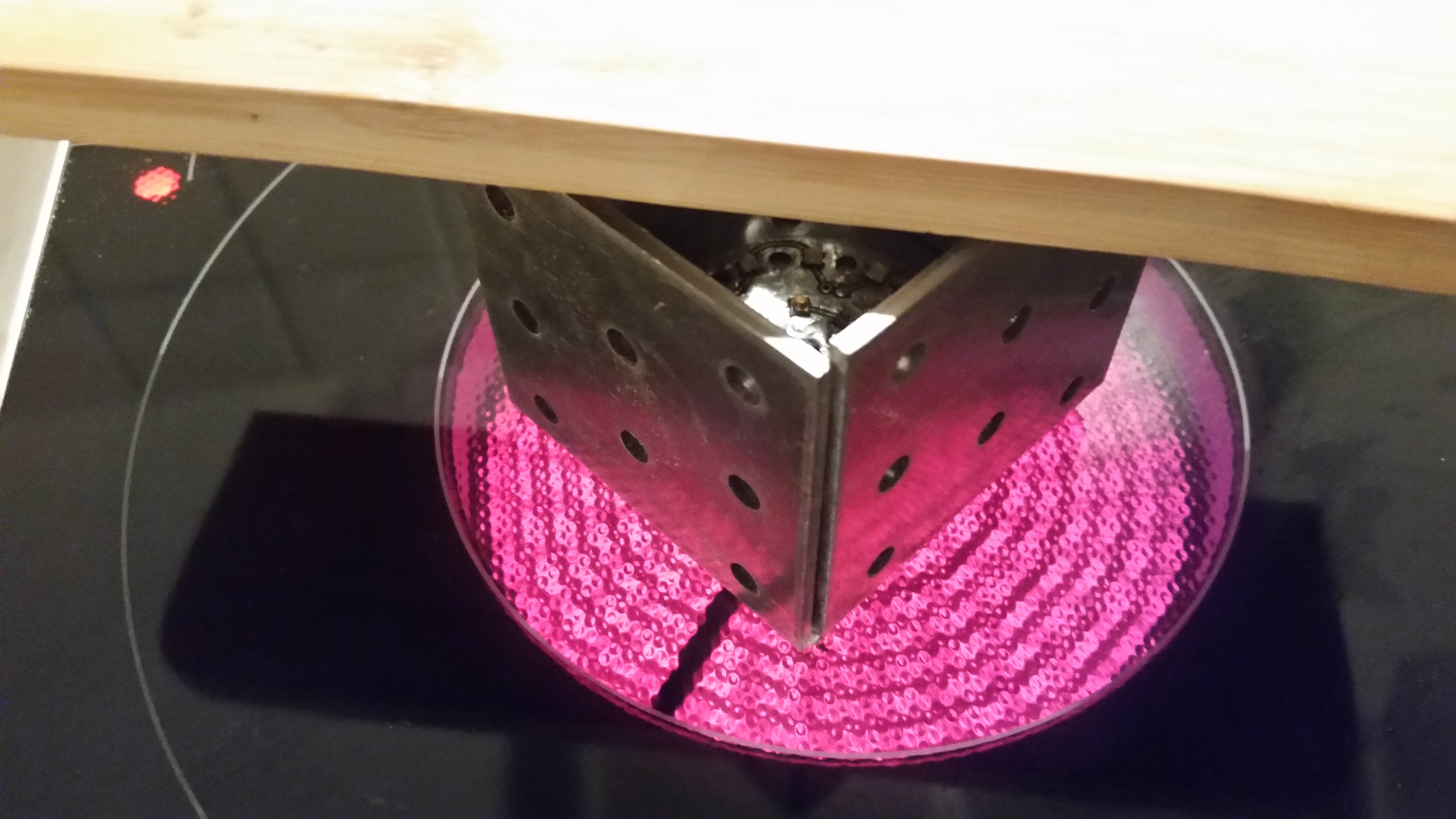
Because the LEDs can not be soldered by hand, I did this step on my oven. The metal brackets keep the heat inside. Then I assembeled everything and applied 1g of thermal grizzly 12.5W/(m*K) paste to ensure a good thermal conductance - especially between the upper side of the board and the screws/rod.
Electronics
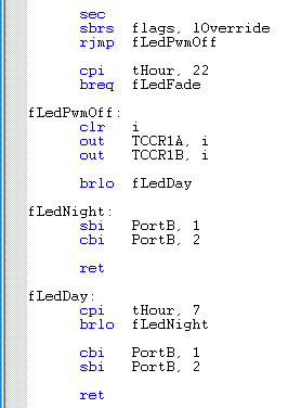
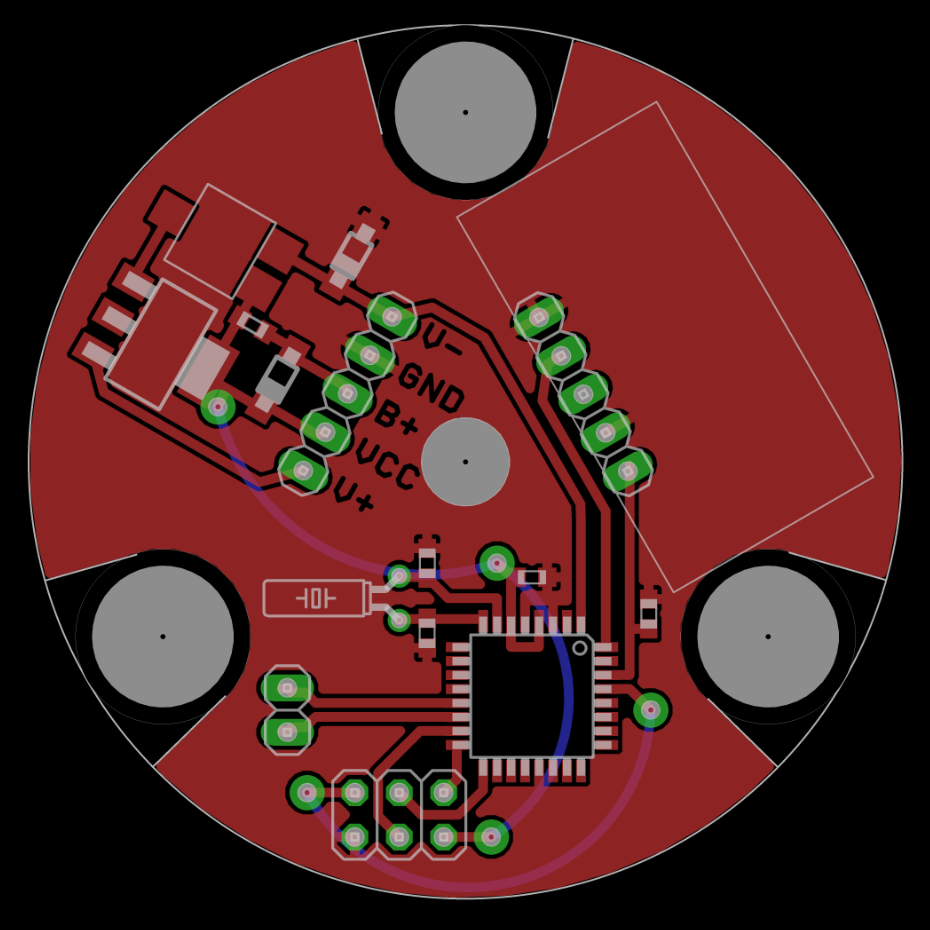
The board sits right between the two heatsinks and is held in place between the three aluminium spacers. It's mostly just an ATMega, a voltage regulator and a DCF77 receiver. I initially planned to have the NiMh RTC backup battery on the board, but then I decided to put it behind the ceiling plate with the power supply so it stays cool and because the heatsinks look better when they are only 10mm apart. How did I route and arrange the parts in a 60° angle? I just turned the whole board. The layout has only a top layer. The bottom layer represents wire connections.
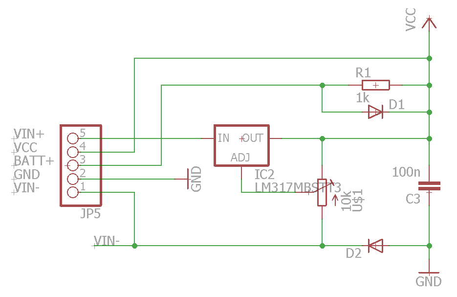
The regulator provides 3.9V and connects to the backup battery via a 1kOhm resistor for trickle charging. The AVR can detect if it is powered by mains or battery. I had to generate a low level when the power supply is switched on, because the AVR needs a low level for its interrupt. This is why the diode is connecting VIN- to ground and not the output of the LM to VCC, like it would be standard procedure. As soon as the light switch is turned off, the voltage between VIN- and VCC drops, resulting in a high level.
Three LM350 provide...
Read more » Matthias Kampa
