 Nick Sayer
This project is somewhat similar to the TPI adapter project. The big difference is that the functions that were on 3 pins for TPI are crammed here into a single pin.
The boost converter to take the input power and convert it to 12 volts is unchanged. However, it is gated onto the UPDI pin this time with a MOSFET that is itself triggered by an RC edge detector. DTE dropping low (which happens when the serial port is opened) will cause the MOSFET gate to be pulled low for about 500 µs, pulsing the pin to +12. After that the TX line is bridged to UPDI by a 1 kΩ resistor. The resistor both protects the TX pin from the 12 volt pulse and insures that the chip is permitted to override the programmer when it wants to speak (as there's no easy way to tri-state the TX pin). On the RX side, we do have to protect the UART from the 12 volt pulse, and that's easily done with with a smaller resistor and a Schottky diode to Vcc (one could argue that the diode is unnecessary as the UART itself almost certainly has the same protection diodes internally, but it's best to be safe).
On the input side, you need 5 pins - Vcc (either +5 or +3.3 volts), ground, TXD, RXD and !DTR. I've chosen to use a 10 pin connector that's pin-compatible with my FTDI-be-gone TTL variant. I'm going to build it with a female connector mounted on the bottom of the board so that it just sort of stacks on top, much like the TPI adapter can stack on top of a USB µISP.
 Adrian Freed
 Mike
Mike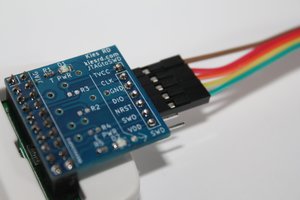
 Engin Subaşı
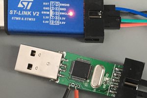
 gertux