Close
0%
0%

The Resistorganizer

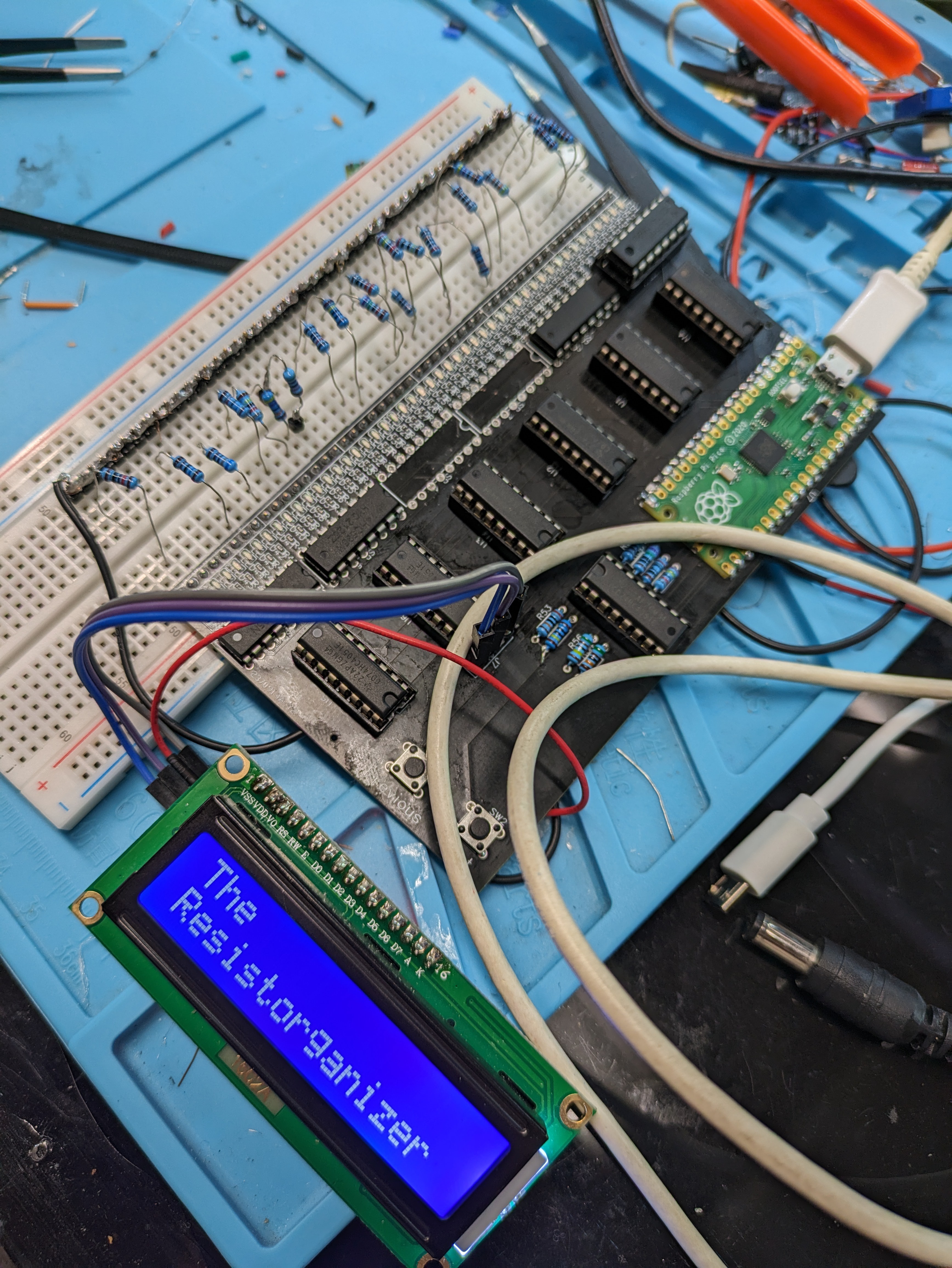
Managing resistors is a chore. Well, with the Resistorganizer, you can just jam your loose resistors into a breadboard and be done with it.

Public Chat
Similar projects worth following
So, my workshop / lab is a mess. Organization isn't my thing. Well, it's not my default setting. Anway, when it comes time to wrap for the day and you have a pile of components on your workbench, what do you do? Do you meticulously sort your resistors? No. You throw them into a pile, a box, or... whatever.
Perhaps you've spent enough time staring at color codes that you can pick up a resistor and immediately tell what its value is. I cannot do this. Nor do I care to. It's only after I stick the resistor in question into a parts tester or multimeter that the color bands on the damn thing make any sense to me. Also, I doubt there are many who can spot the value they need from within the pile. So, we tend to take a new one from stock and the pile grows.

Here's the idea, just stick your loose resistors into a breadboard. Then, a microcontroller can do the keeping track.

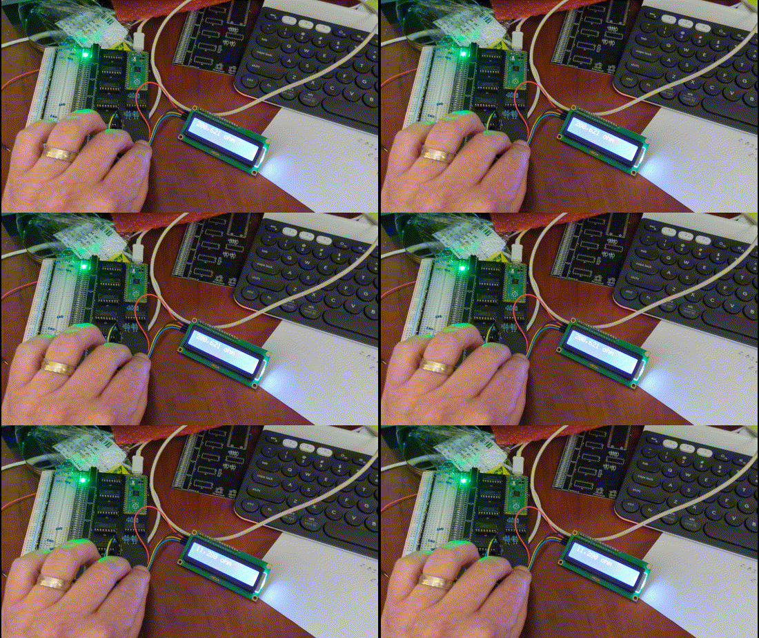
'Finished' Prototype Video:
https://youtu.be/DDRz76K1jgc


What the hell is this?

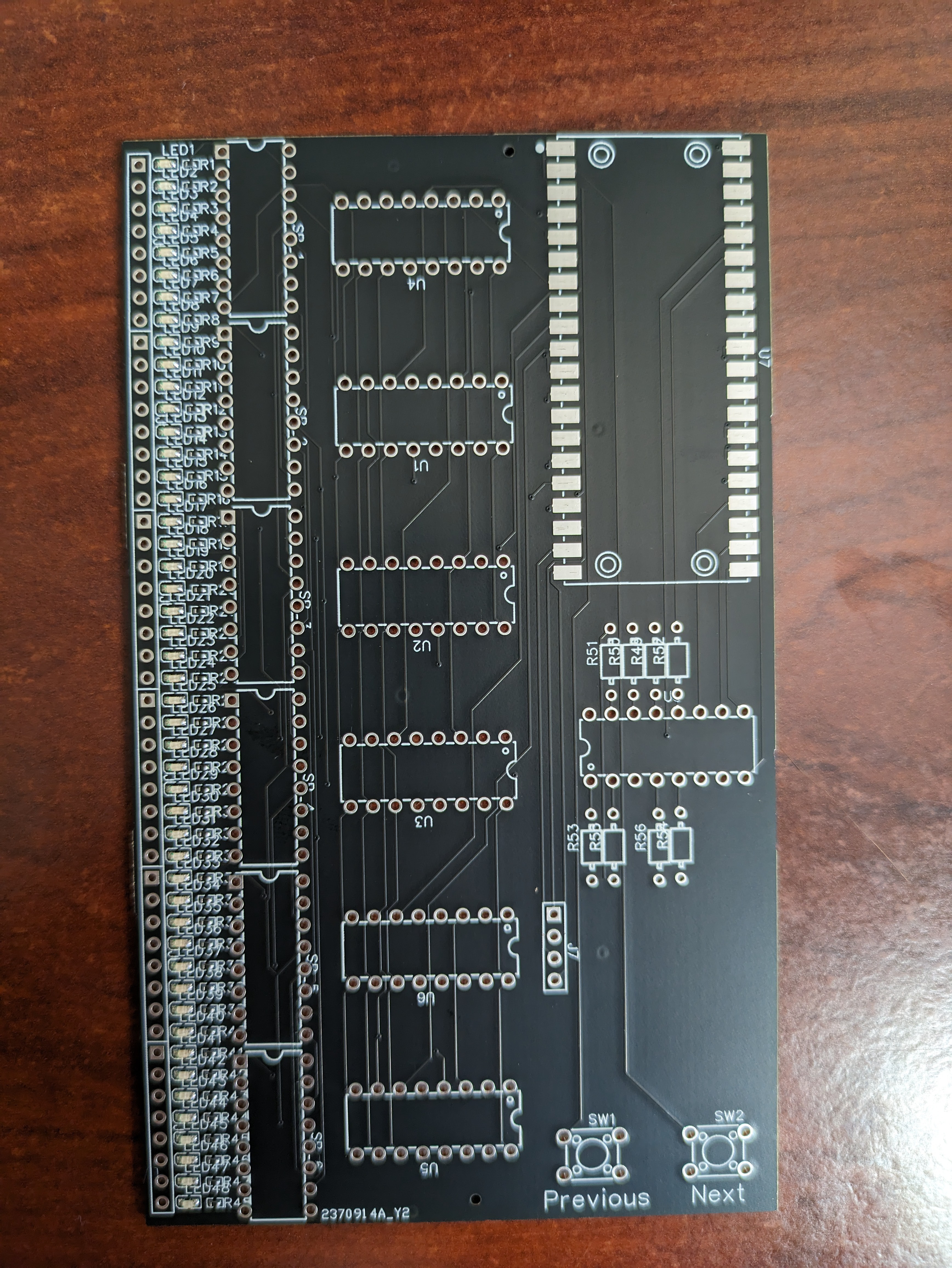
At a high level, the Resistorganizer is a PCB that you can plug into a standard solderless breadboard and it will poll the rows and determine the resistance value of the resistor which is plugged into it (across the DIP gap). 
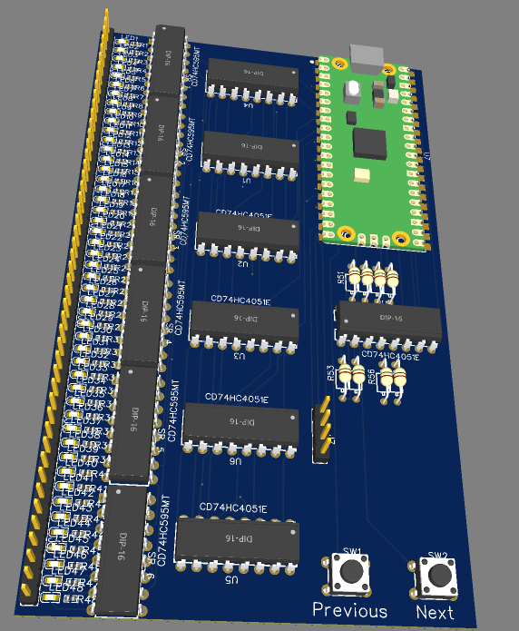
The board is driven by a RPi Pico, utilizing the ADC and some reference resistors to determine each resistor's value based on the voltage divider equation:

Where, in this case, the board is set up that all the resistors stored in the breadboard are R2. 

So, that's all well and good, but without some automation, it would be easier to just check the values with a multimeter. Let's expand our ADC.

Shift Happens

At the heart of this board is a handful of a cool IC, the CD74HC4051 analog multiplexer. This was a revelation to me that (of course) there's a chip out there that can act like a switch and multiplex an ADC. I'm inspired by this chip's bi-directionality. It should be noted that this chip has been replaced by TI with the MUX4051, a drop in replacement with better features. 

Since this chip isn't going to be doing hard core signal switching, it's likely an overkill solution. But, if something needs to be killed, you might as well overkill it. 

The 4051 has an 8:1 set-up, where you can poll 8 separate signals to the common terminal. Which channel is being polled is controlled with 3 address pins. The chip also has an enable pin, which effectively shuts the chip down. So, after the three address lines and the 'output' line,  each chip only requires a single pin from your microcontroller to read up to 8 signals. Hell, you could throw another generic multiplexer to handle the chip enable pins and get a whole slew of ADC input for a total of... what is that... 3 address pins, 1 ADC, 1 Clock, 1 Latch, 1 serial... so 7 pins for up to a... crap-ton of ADC goodness. I think this is very cool. 

Measuring Resistance Isn't that Straightforward... apparently.

Let's revisit the voltage divider equation again and take a look at an issue that arises from ADC precision (or lack thereof): 

Vout / Vin = R2 / R1 + R2

In theory, it should be a trivial exercise in algebra to determine R2 if Vout, Vin and R1 are known. Sure. But, in reality, there are things to consider.  The ADC is going to give you a value (in the case of the pico) between 0 and 4095 (12 bits). Where 0 = 0 volts and 4095 = ADCVref (3.3 v). Great, so if the reading is 2053 we can calculate Vout.

Yay. Based on the ratio of the max ADC value and the observed ADC value (~0.5) we can calculate that the resistance of R2 is very nearly equal to R1. Great. But, what if R1 is much, much higher or lower than R2? Well, looking at the equation at the top, as R2 gets much greater than R1, the ratio approaches 1 which would result in the output voltage being equal to the input voltage. The inverse is true as R2 is much smaller than R1, the ratio approaches zero and therefore the output voltage approaches zero. 

Resistors commonly used range in values from 220 ohm to 2,000,000 ohm. That's around 2 million values that need to be crammed into 4095 intervals. Precision isn't going to be straightforward here since one ADC interval will cover several resistance values and no one reference resistor for R1 is going to do a good job at R1. 

I should have done some research on how a standard ohmmeter does this measurement. But I didn't. I want to roll my own solution. Here's what I came up with and it involves another CD74HC4051. (edit) I did some research and found out that ohmmeters commonly use a current sensor to determine the resistance. I have an ACS712 but a look at the datasheet makes me think that it won't be handling milliamp / microamp scale very well. So... back to the original idea.

The plan to mitigate this precision problem is to select 8 resistors for reference that will range from 220Ω to 2MΩ. These will be multiplexed as R1. So, for each R2 in the breadboard,...

Read more »

  • 'Finished' Prototype

    Mike09/05/2023 at 16:40 0 comments

    Forced to the Ground:

    After some debugging, head-scratching and swearing I couldn't find the reason why the enable pin was being held high on the HC595 shift registers when more than two registers were populated on the board. Eventually I gave up and measured the current flowing from the enable to ground, saw that it wasn't too much, and bodged in a 11k pull-down resistor to an adjacent chip's ground and called it good. 

    What Next?

    I would like to fix / do the following: 

    • Revise the schematic and resolve the pull-down issue
    • Make the shape of it more breadboard friendly with the display at the top and generally keeping the breadboard more in the center of the design
    • Expand it to fill more of a standard breadboad
    • include header pins for expansion to multiple breadboards. 

    When Will That Happen?

    Honestly, I don't know. This project started with me feeling stuck in my workspace because organizing is a chore. Now that I have The Resistorganizer, I have what I want and (selfishly) that's what is important to me at the moment. This was always intended to be a tool rather than something I'd turn into a product for release. Nevertheless, I do want to share my work, so that anyone can take it an build their own or run with it. So, I'll revise the schematic to the best of my ability, but beware, there be bugs. Once I have it in a condition I feel comfortable sharing, I'll put them in this .io project. 

    THANK YOU!

    This is my first project on Hackaday.io and I want to express how rad I think this community is and say thanks to all who provided insight and encouragement. I learned a lot from this project and a lot of that came from you. Cheers.

  • Well, Damn.

    Mike09/03/2023 at 16:45 0 comments

    Well, my shift registers arrived yesterday. I was very excited to get them soldered in and to see The Resistorganizer 1.0 do the thing will all its blinkenlights. 

    Alas, this is where trouble reared it's unconventionally pretty head.

    Once installed, the LED don't light up at all now. My guess is that my schematic had some wiring wrong (I've since revised the schematic before I knew of this problem and didn't save the previous version.<face_palm_emoji>, but I can refer to my original files sent to the PCBA house)

    So, I started cutting out shift registers to see if the lights would come back, at least to the first two registers which worked before. 

    As you can see in the photo, I've clipped out two so far with no luck. So... keep clipping? Let's hold off for now. Time to get the multimeter out and see if I can tell what's what. Then, we'll get destructive again. 

    Yea, yea, yea... I should go find the file with the board schematic and start troubleshooting there. That makes the most sense. But I'll spend 10 minutes finding the file and 45 minutes putzing around the kitchen because, for whatever reason, the mind really doesn't want to engage that way. So, we're working with the mind I've got. 

  • The First Bits of Code (pun unintended)

    Mike08/31/2023 at 15:55 3 comments

    Microscopic Snakes of the Constricting Variety:

    I'm initially writing the code for this in Micropython, which as we all know is great for prototyping but doesn't have the speed or the flexibility of C/C++. I'm fine with this trade-off. Really, I am. Don't let the obvious doubt in my voice tell you any different. Which means, we'll be using...

    Thonny:

    Thonny is rad. It's come a long way since the first time I laid eyes on it. The RPi Pico integrates seamlessly with it. But, here's the rub. I hate using it. Here's the part where I'm tempted to say that I use Vim as my daily editor. I don't. I use VSCode; shameful as that may be. But, I'm a big fan of copilot and standing on the AI generated amalgam of shoulders of giants. Again, shameful as that may be. But I know tons of you out there who'll never post a comment use VSCode with copilot. Those of you that will leave a comment will tell me how much better their choice of editor / workflow is. Please do leave these comments! As a person whose neuro-biology forces them to constantly question their set-up, then reconfigure it endlessly rather than actually finishing a project, I need your ideas to keep me from actually conquering the universe. So, I'm using Thonny, and occasionally copy /  pasting my code into VSCode to get some of that sweet AI suggestions. Bring on the flames all you Thonny fanboys (said in my best Dave Jones accent). I think this haiku sums it up nicely:

    Thonny's not my jam
    For Pico, yet it's not bad—
    Habit ties my hands.

    Read more »

  • Populating (sort of) the First Board

    Mike08/30/2023 at 20:27 0 comments

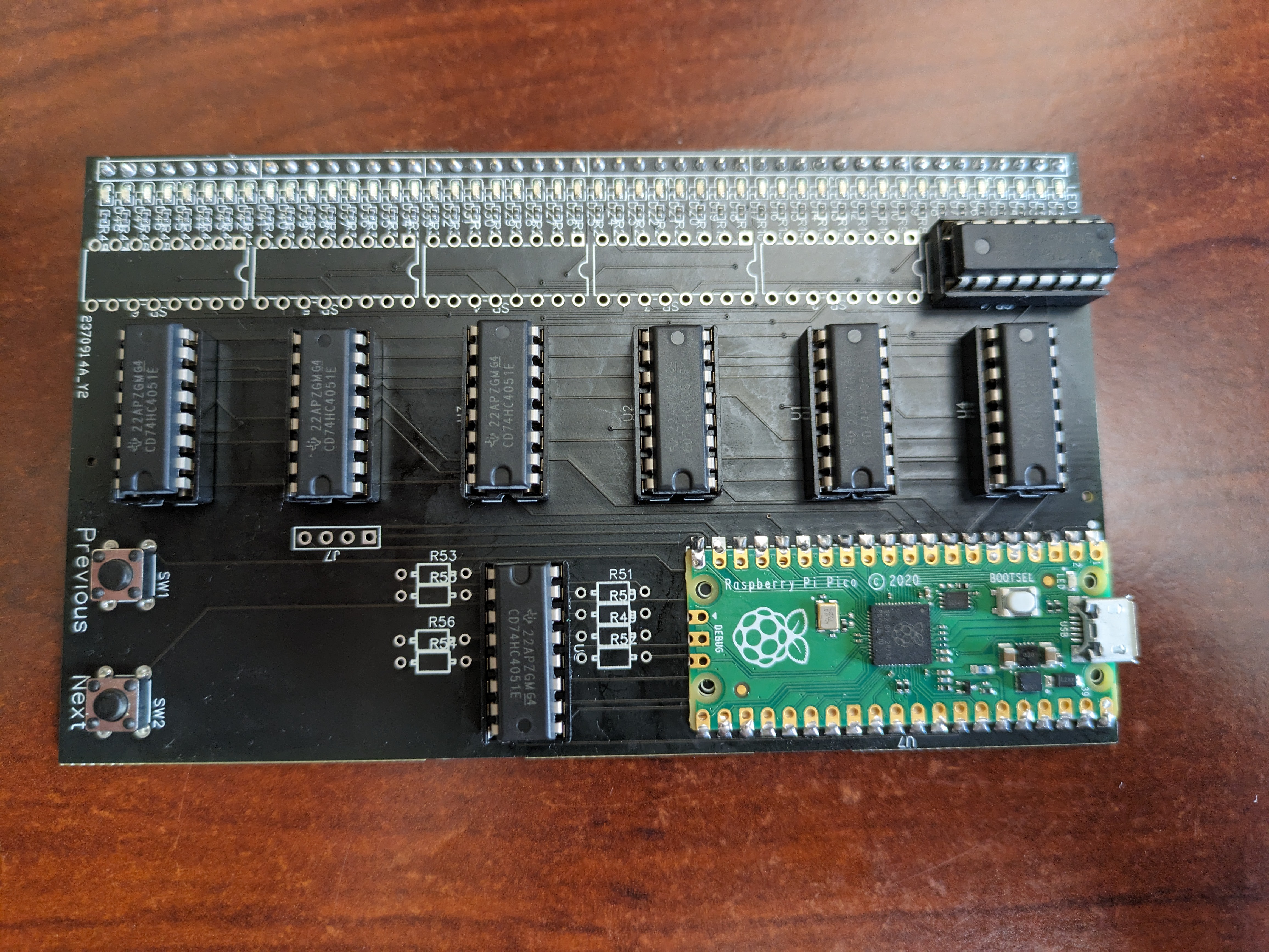
    The boards arrived early and it's time to see if any of this will work.

    I head into the disaster that is my workspace and quickly realize that I used up all my SN74HC595N digital shift registers, save one. I should have taken @Ken Yap's advice and just has this all SMD'd up and be done with it. Debugging be damned. 

    But that's okay. I have at least one of the digital shift registers so I can test the first 8 LEDs. 

    Sockets?

    Yea, I put the components in sockets. I figure if this is all donked up, I can fix it and reuse the components. 

    No socket for the RPi Pico?

    Yea, shut up.

    Let's get to some preliminary programming and see if this works. Fire up Chat-GPT and away we go!

  • Surprise Motherhacker!

    Mike08/30/2023 at 18:50 0 comments

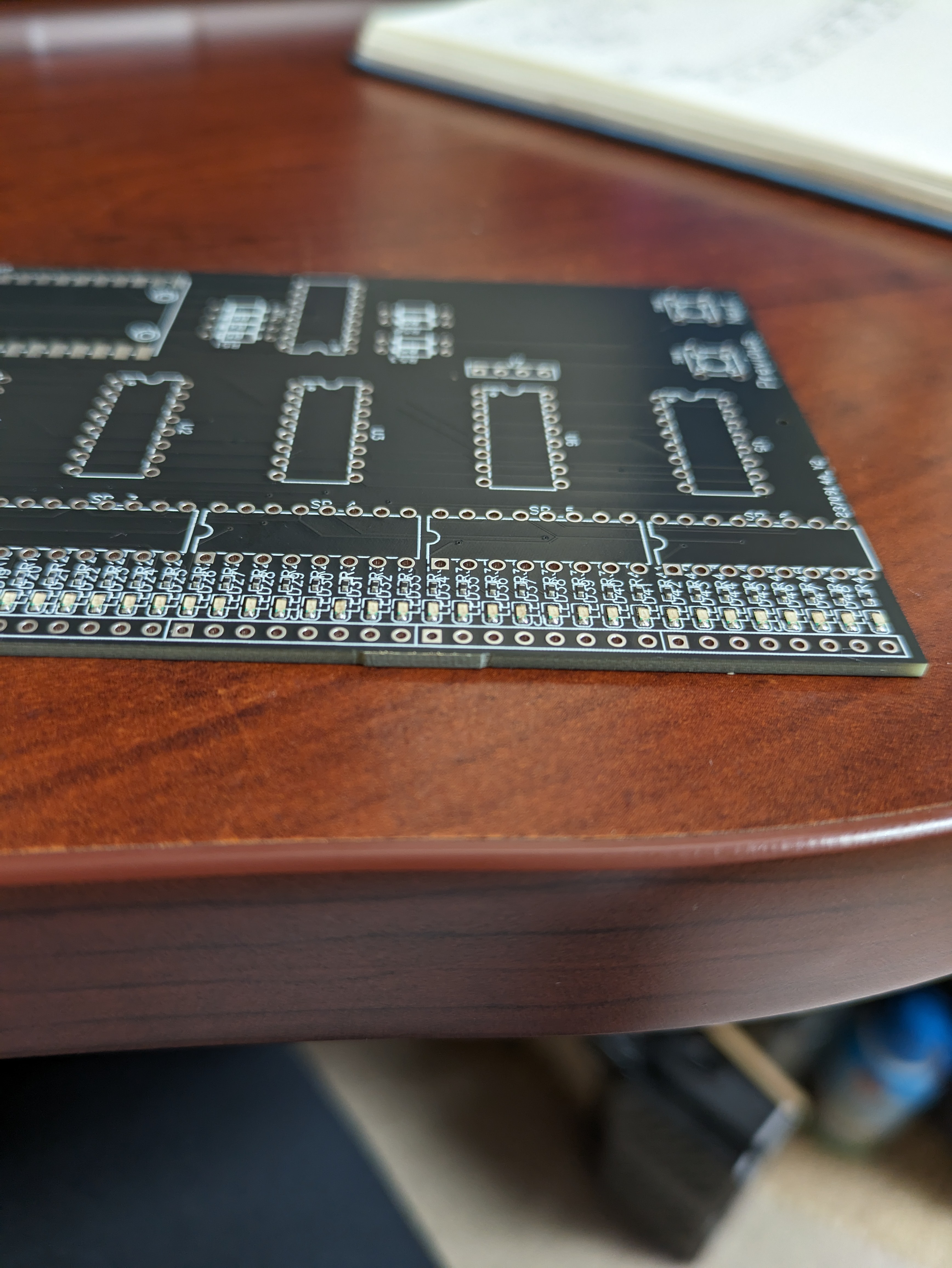
    The Boards Arrived Early!

    I'm excited to see that my boards arrived early! Time to see if my wiring is okay.

  • Awaiting Boards from Far Off Lands

    Mike08/30/2023 at 12:20 2 comments

    There's no way I'm going to be able to hand solder 96 tiny SMD components.

    This is a direct quote from my brain. 

    I watch enough YouTube to know that there are a handful of PCB houses on the planet that want my business and are willing to accept my first attempt at PCB design and dutifully execute the details of my Gerber Baby files, pick and place spreadsheet and BOM. Terrifying. 

    The boards should arrive tomorrow and I'm very excited about it. Just holding a PCB (let alone a stack of them) that I designed is going to be a thrill. I haven't made a PCB since high school. 

    That being said, I will be astonished if this project works on the first try. Yes, I checked and double checked my connections and whatnot. I did (sort of) prototype the circuitry on a breadboard. But, I fully expect something to be terribly wrong and that debugging will take a while. 

    I'll be sure to keep you posted.

    The search for the 2022 Gerber Baby is on - WSVN 7News | Miami News,  Weather, Sports | Fort Lauderdale

View all 6 project logs

Enjoy this project?

Share

Discussions

Isaac Wingfield wrote 09/02/2023 at 03:44 point

In fact, it's rare to actually require any resistor value to be more precise than 1 or 2 or 5 (1, 2.2, 4.7) plus a multiplier. I just sort my resistors into ten drawers by the third stripe.

  Are you sure? yes | no

Mike wrote 09/03/2023 at 02:46 point

I'm sure that you're right. Especially for digital circuits. I'm getting into analog circuits, specifically guitar pedals. Will 4k resistor sound different from a 4k4? Likely not. But, when I'm following someone else's circuit design, and it doesn't sound right, I'm going to be wondering if my choice of resistor is making a difference or the difference. Active signal filters can be finicky. I like the idea of keeping the variables to a minimum when trying to figure out why everything I make is garbage. 

The system you describe is one of the better ones I've come across. 

  Are you sure? yes | no

Isaac Wingfield wrote 09/03/2023 at 03:52 point

Nope; I was talking about analog; digital takes even fewer values unless you're mixing types. For filters you need some precision, but for other things, not so much. The best analog -- and filter -- designer I ever knew was the one who taught me the 1, 2.2, 4.7 thing.

  Are you sure? yes | no

Kevin Santo Cappuccio wrote 08/30/2023 at 01:53 point

Hey I see that you're going to just the ADC on the RPi Pico and I'd thought I'd share a hard-won tidbit of knowledge I just recently fought with.

The ADCs on a Pico kick like a friggin' mule. It has a particularly low input impedance, so it acts like a ~100K resistor to 3.3V (or ground, I don't remember)  when taking a measurement. Luckily, it's an easy fix to just throw in a simple op amp voltage follower as a buffer. 

Or you can use the INA219 Current/voltage monitor that will tell you both the current and the voltage at the same time over I2C. Maybe with a simple ranging setup like I did for this project (or just have 2-3 always connected with different sense resistors, I only needed ranging because the current/voltages involve for this were unknown and possibly huge):

https://hackaday.io/project/192475-humoring-james-newton

The INA219

https://www.ti.com/lit/ds/symlink/ina219.pdf

  Are you sure? yes | no

Mike wrote 08/30/2023 at 18:44 point

YES! Thank you!

I knew I should have read the datasheet for the 2040 more carefully (ahem, or at all really). I suspected that there'd be an impedance issue, but second guessed the impact since it's dealing with DC. Buuut, your comment makes me realize that it doesn't matter whether or not it's AC or DC. If it looks like a 100k resistor to ground (or whatever) it's going to impact the reading. I was very close to implementing an op amp buffer (god knows I have enough op amps lying around [for making guitar pedal circuits]) but (wrongfully) assumed that the 2040 ADC input wouldn't be such a current sucker. 

PCBs just arrived!

I'm going to follow your links and read-up on your project. It looks like I can use a lot of your hard-won knowledge. 

  Are you sure? yes | no

Kevin Santo Cappuccio wrote 08/25/2023 at 01:51 point

This is a rad idea! You can use this thing I make to get you partway there.
https://www.tindie.com/products/architeuthisflux/jumperlux/
Message me for a steep discount code, because I want this thing to exist.

  Are you sure? yes | no

Mike wrote 08/29/2023 at 20:30 point

Thank you! And wow! The jumperlux looks very, very cool. I wanted to reply before I read through your project writeup, in case i'd forget. 

I think this thing will exist. I've ordered the prototypes from JLCPCB (No way I'm going to solder 96 smd LEDs & resistors) and they should arrive Thursday. To that point, a 100 row Jumperlux would be amazing. I saw that they're extensible. so rad. It'd be perfect for the indicators.

I've made some updates to the description and look forward to feedback. 

Thanks again!

  Are you sure? yes | no

Similar Projects

Does this project spark your interest?

Become a member to follow this project and never miss any updates