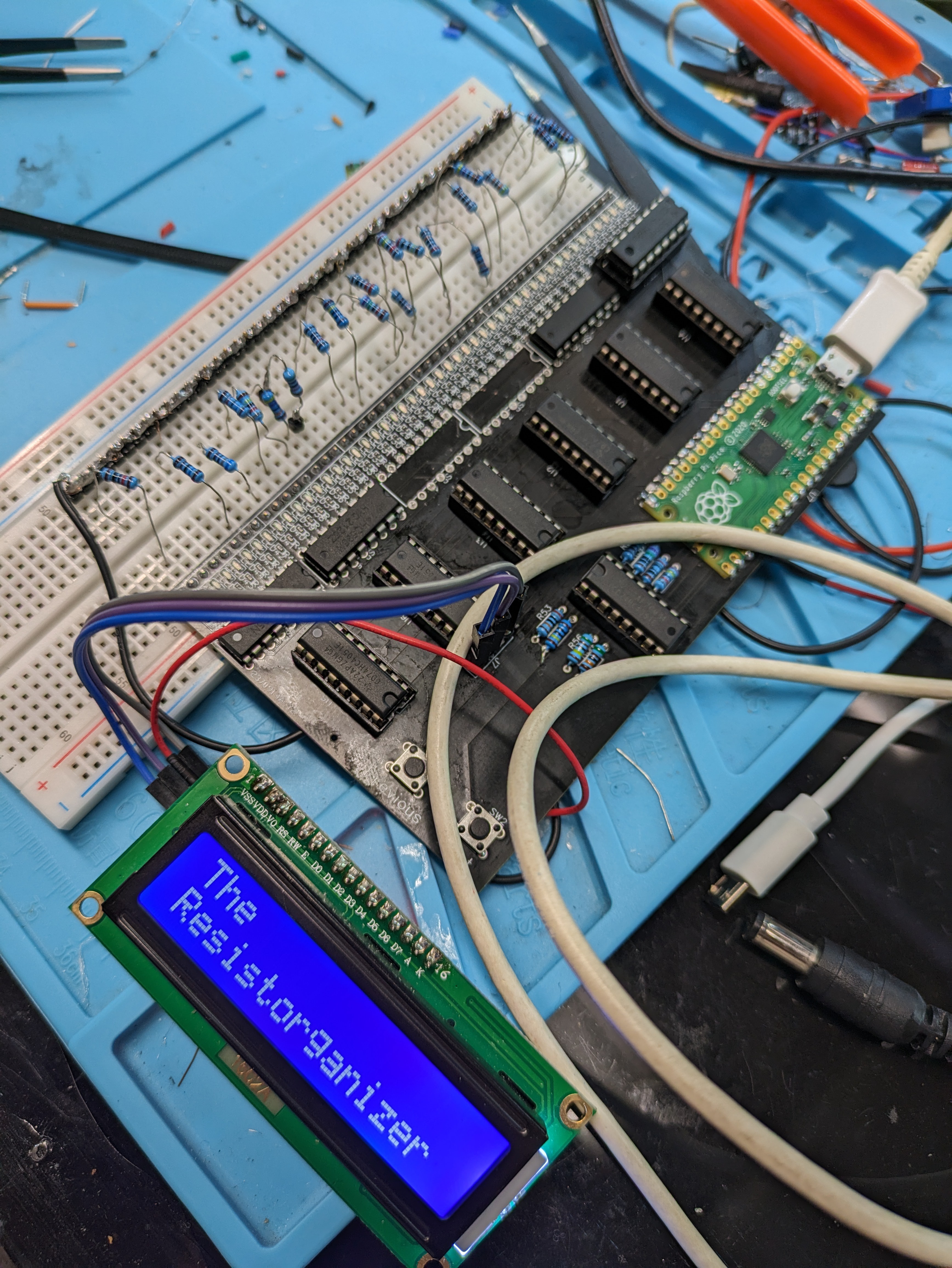
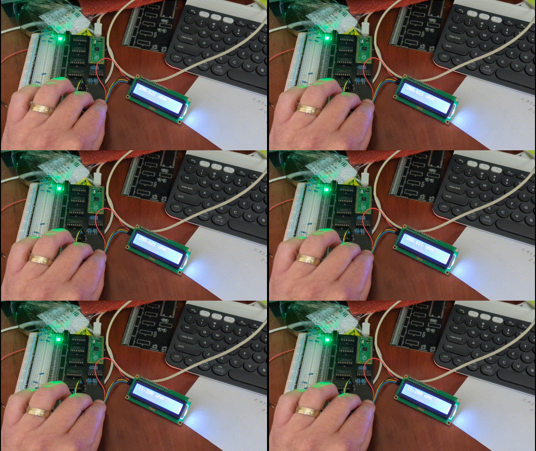
-
'Finished' Prototype
09/05/2023 at 16:40 • 0 commentsForced to the Ground:
After some debugging, head-scratching and swearing I couldn't find the reason why the enable pin was being held high on the HC595 shift registers when more than two registers were populated on the board. Eventually I gave up and measured the current flowing from the enable to ground, saw that it wasn't too much, and bodged in a 11k pull-down resistor to an adjacent chip's ground and called it good.
What Next?
I would like to fix / do the following:
- Revise the schematic and resolve the pull-down issue
- Make the shape of it more breadboard friendly with the display at the top and generally keeping the breadboard more in the center of the design
- Expand it to fill more of a standard breadboad
- include header pins for expansion to multiple breadboards.
When Will That Happen?
Honestly, I don't know. This project started with me feeling stuck in my workspace because organizing is a chore. Now that I have The Resistorganizer, I have what I want and (selfishly) that's what is important to me at the moment. This was always intended to be a tool rather than something I'd turn into a product for release. Nevertheless, I do want to share my work, so that anyone can take it an build their own or run with it. So, I'll revise the schematic to the best of my ability, but beware, there be bugs. Once I have it in a condition I feel comfortable sharing, I'll put them in this .io project.
THANK YOU!
This is my first project on Hackaday.io and I want to express how rad I think this community is and say thanks to all who provided insight and encouragement. I learned a lot from this project and a lot of that came from you. Cheers.
-
Well, Damn.
09/03/2023 at 16:45 • 0 comments![]()
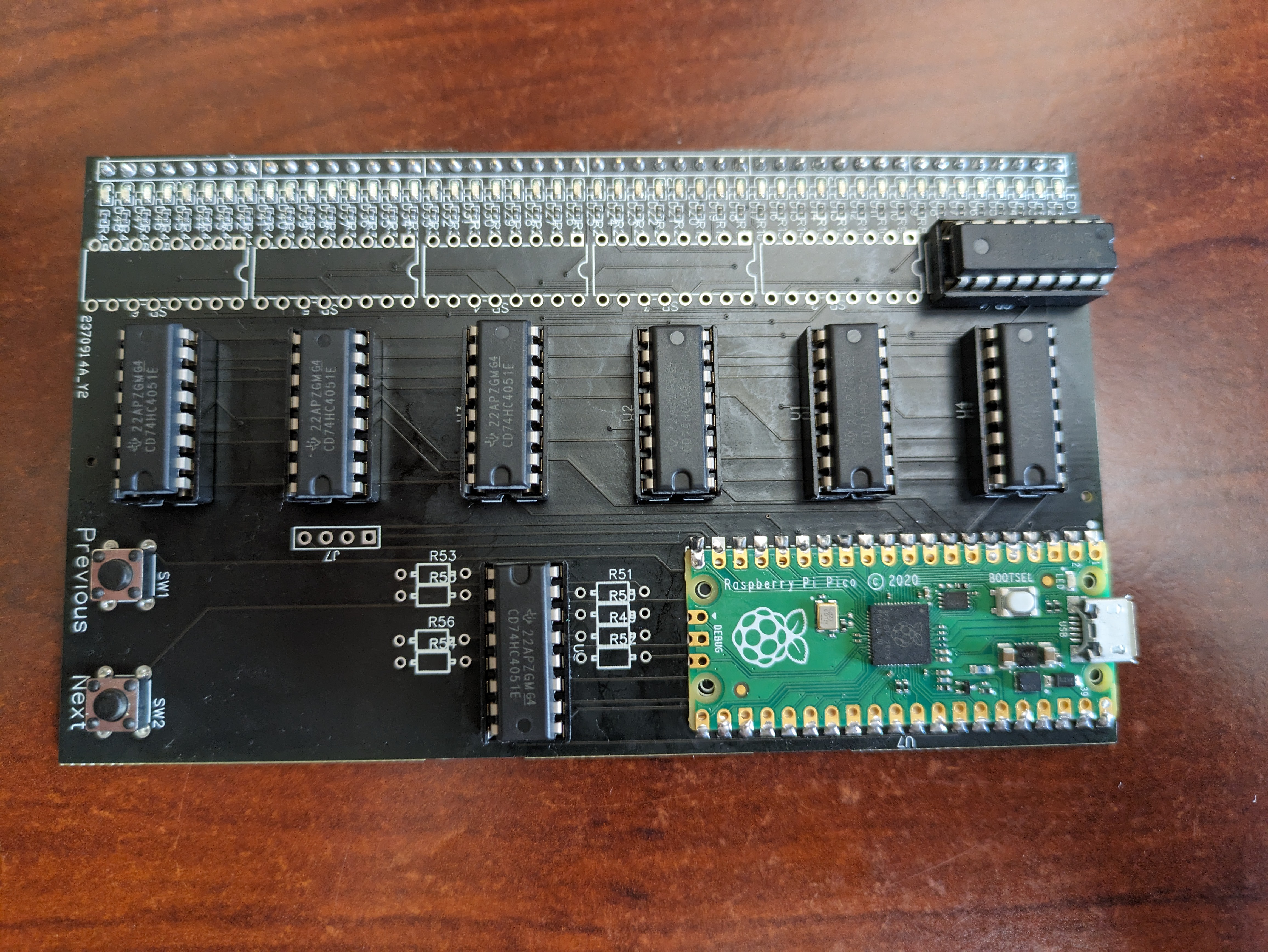
Well, my shift registers arrived yesterday. I was very excited to get them soldered in and to see The Resistorganizer 1.0 do the thing will all its blinkenlights.
Alas, this is where trouble reared it's unconventionally pretty head.
Once installed, the LED don't light up at all now. My guess is that my schematic had some wiring wrong (I've since revised the schematic before I knew of this problem and didn't save the previous version.<face_palm_emoji>, but I can refer to my original files sent to the PCBA house)
So, I started cutting out shift registers to see if the lights would come back, at least to the first two registers which worked before.
As you can see in the photo, I've clipped out two so far with no luck. So... keep clipping? Let's hold off for now. Time to get the multimeter out and see if I can tell what's what. Then, we'll get destructive again.
Yea, yea, yea... I should go find the file with the board schematic and start troubleshooting there. That makes the most sense. But I'll spend 10 minutes finding the file and 45 minutes putzing around the kitchen because, for whatever reason, the mind really doesn't want to engage that way. So, we're working with the mind I've got.
-
The First Bits of Code (pun unintended)
08/31/2023 at 15:55 • 3 commentsMicroscopic Snakes of the Constricting Variety:
I'm initially writing the code for this in Micropython, which as we all know is great for prototyping but doesn't have the speed or the flexibility of C/C++. I'm fine with this trade-off. Really, I am. Don't let the obvious doubt in my voice tell you any different. Which means, we'll be using...
Thonny:
Thonny is rad. It's come a long way since the first time I laid eyes on it. The RPi Pico integrates seamlessly with it. But, here's the rub. I hate using it. Here's the part where I'm tempted to say that I use Vim as my daily editor. I don't. I use VSCode; shameful as that may be. But, I'm a big fan of copilot and standing on the AI generated amalgam of shoulders of giants. Again, shameful as that may be. But I know tons of you out there who'll never post a comment use VSCode with copilot. Those of you that will leave a comment will tell me how much better their choice of editor / workflow is. Please do leave these comments! As a person whose neuro-biology forces them to constantly question their set-up, then reconfigure it endlessly rather than actually finishing a project, I need your ideas to keep me from actually conquering the universe. So, I'm using Thonny, and occasionally copy / pasting my code into VSCode to get some of that sweet AI suggestions. Bring on the flames all you Thonny fanboys (said in my best Dave Jones accent). I think this haiku sums it up nicely:
Thonny's not my jam
For Pico, yet it's not bad—
Habit ties my hands.
---------- more ----------Enough Loops to Make Girltalk Blush:
Yea, so here's the initial code:
from machine import Pin, I2C, ADC
import utime
from lcd_api import LcdApi
from pico_12c_lcd import I2cLcd

I2C_ADDR     = 39
I2C_NUM_ROWS = 2
I2C_NUM_COLS = 16
i2c = I2C(1, sda=Pin(14), scl=Pin(15), freq=400000)
lcd = I2cLcd(i2c, I2C_ADDR, I2C_NUM_ROWS, I2C_NUM_COLS)


# print(i2c.scan())
# print(type(i2c.scan()[0]))
# utime.sleep(3)

adc_pin = ADC(Pin(26))

ser_pin = Pin(8, Pin.OUT)
srclk_pin = Pin(12, Pin.OUT)
rclk_pin = Pin(13, Pin.OUT)

prev_button = Pin(0, Pin.IN, Pin.PULL_UP)
next_button = Pin(1, Pin.IN, Pin.PULL_UP)

sense_pins = [Pin(21, Pin.OUT), Pin(20, Pin.OUT), Pin(19, Pin.OUT)]
ref_pins = [Pin(18, Pin.OUT), Pin(17, Pin.OUT), Pin(16, Pin.OUT)]
adc_enable_pins = [Pin(2, Pin.OUT), Pin(3, Pin.OUT), Pin(4, Pin.OUT), Pin(5, Pin.OUT), Pin(6, Pin.OUT), Pin(7, Pin.OUT)]
led_enable_pin = Pin(12, Pin.OUT)
ref_enable_pin = Pin(10, Pin.OUT)
shift_clear = Pin(11, Pin.OUT, value=1)

reference_resistances = (200, 750, 1500, 24000, 200000, 510000, 1000000, 5100000)

ref_enable_pin.low()
led_enable_pin.low()

current_index = 0
# Define debounce delay in milliseconds
debounce_delay_ms = 50

custom_omega = [
    0b00000,
    0b00100,
    0b01010,
    0b10001,
    0b10001,
    0b01010,
    0b00100,
    0b00000,
]

# Load the custom character into a custom slot (check your LCD's documentation)
I2cLcd.custom_char(lcd, 0, custom_omega)


def debounce_button(pin):
    # Wait for the button state to settle
    utime.sleep_ms(debounce_delay_ms)
    return pin.value()

def previous_button_pressed(pin):
    global current_index
    if debounce_button(pin) == 0:
        if current_index > 0:
            current_index -= 1
        else:
            current_index = len(big_array) - 1
        shift_out(1 << big_array[current_index][1])
        print(big_array[current_index][1]+1,": ", big_array[current_index][-1], "Ohms")
        lcd.clear()
        lcd.putstr(big_array[current_index][-1]+ " ohm")

def next_button_pressed(pin):
    global current_index
    if debounce_button(pin) == 0:
        if current_index < len(big_array) - 1:
            current_index += 1
        else:
            current_index = 0
        shift_out(1 << big_array[current_index][1])
        print(big_array[current_index][1] +1,": ", big_array[current_index][-1], "Ohms")
        lcd.clear()
        lcd.putstr(big_array[current_index][-1]+ " ohm")
        # lcd.putchar(0)

# Attach interrupt handlers to buttons
prev_button.irq(trigger=Pin.IRQ_FALLING, handler=previous_button_pressed)
next_button.irq(trigger=Pin.IRQ_FALLING, handler=next_button_pressed)


def latch():
    rclk_pin.on()
    utime.sleep_us(1)
    rclk_pin.off()

def shift_out(data):
    for _ in range(8):
        ser_pin.value(data & 0x80)
        srclk_pin.on()
        utime.sleep_us(1)
        srclk_pin.off()
        data <<= 1
    latch()


#create big array to hold all the adc readings
big_array = []

def enable_adc(a):
    for i in range(len(adc_enable_pins)):
        # Set the current enable pin low and others high
        adc_enable_pins[i].value(0 if i == a else 1)

def set_adc(a):
    # Convert the decimal value 'a' to a binary string
    binary_string = bin(a)[2:]
    while len(binary_string) < 3:
        binary_string = '0'+ binary_string
    binary_string = list(reversed(binary_string))
    for i in range(len(binary_string)):
        sense_pins[i].value(int(binary_string[i]))

def set_ref(a):
    # Convert the decimal value 'a' to a binary string
    binary_string = bin(a)[2:]
    while len(binary_string) < 3:
        binary_string = '0'+ binary_string
    binary_string = list(reversed(binary_string))
    for i in range(len(binary_string)):
        ref_pins[i].value(int(binary_string[i]))

def number_formatter(number):
    return "{:,}".format(number)

def scan():
    # Loop through all enable pins
    for e in range(len(adc_enable_pins)):
        enable_adc(e)


        # print("Enabling pin:", e)
        # print([p.value() for p in adc_enable_pins])


        for i in range(8):
            # Light the LED
            shift_out(1 << i)

            set_adc(7-i)

                # create an array to hold the adc readings
            adc_read_array = []
            for k in range(8):
                set_ref(k)
                avg_array = []
                for r in range(3):
                    avg_array.append(adc_pin.read_u16())
                adc_read_array.append(sum(avg_array)/len(avg_array))

                # print("ASR: ", e)
                # print("ADC Address:", binary_string_adc, " ---- ", i)
                # print("REF Address:", binary_string_ref, " ---- ", k)
                # print("ADC values:", adc_read_array)
                # utime.sleep_us(1)

            # min_index = min(range(len(adc_read_array)), key=lambda i: abs(adc_read_array[i] - 65535))
            # Calculate the index of the minimum absolute difference
            min_index = min(range(len(adc_read_array)), key=lambda i: abs(adc_read_array[i] - (65535/2)))
            # print("Index of Minimum: ", min_index)
            adc_value = adc_read_array[min_index]
            # print("ADC Value: ", adc_value)
            R1 = reference_resistances[min_index]
            # print("R1: ", R1, " Ohms")
            R2 = R1 * (1 / ((65535 / adc_value) - 1))
            R2 = int(R2)
            # R2 = number_formatter(R2)
            print("R2: ", R2, " Ohms")
            if int(R2 < 4000000):
                seq = int(e)*8 + int(i)
                shift_out(1 << seq)
                big_array.append((str(e)+ str(i), seq, adc_read_array, min_index, adc_value, R1, number_formatter(R2)))
            # print(big_array)
# utime.sleep(.5)
scan()
for idx,poop in enumerate(big_array):
    print(idx +1, poop)
# while True:
#     utime.sleep(.1)
So, this is me being in 'get shit done' mode. I couldn't figure out how to get the debugger to work. So... yea lot's of print statements. And less loops than I thought.
-
Populating (sort of) the First Board
08/30/2023 at 20:27 • 0 comments![]()
The boards arrived early and it's time to see if any of this will work.
I head into the disaster that is my workspace and quickly realize that I used up all my SN74HC595N digital shift registers, save one. I should have taken @Ken Yap's advice and just has this all SMD'd up and be done with it. Debugging be damned.But that's okay. I have at least one of the digital shift registers so I can test the first 8 LEDs.
Sockets?
Yea, I put the components in sockets. I figure if this is all donked up, I can fix it and reuse the components.
No socket for the RPi Pico?
Yea, shut up.
Let's get to some preliminary programming and see if this works. Fire up Chat-GPT and away we go!
-
Surprise Motherhacker!
08/30/2023 at 18:50 • 0 commentsThe Boards Arrived Early!
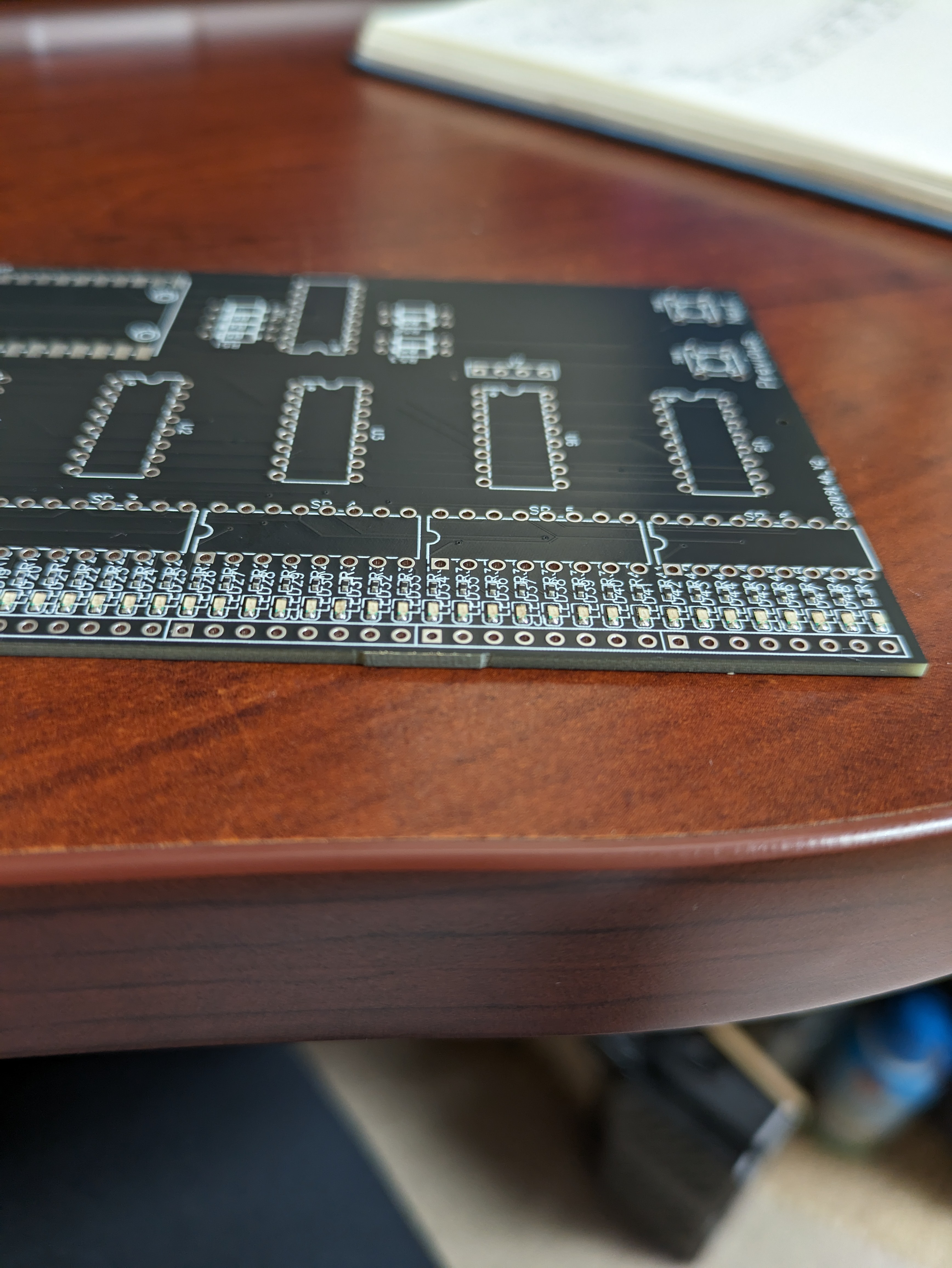
I'm excited to see that my boards arrived early! Time to see if my wiring is okay.
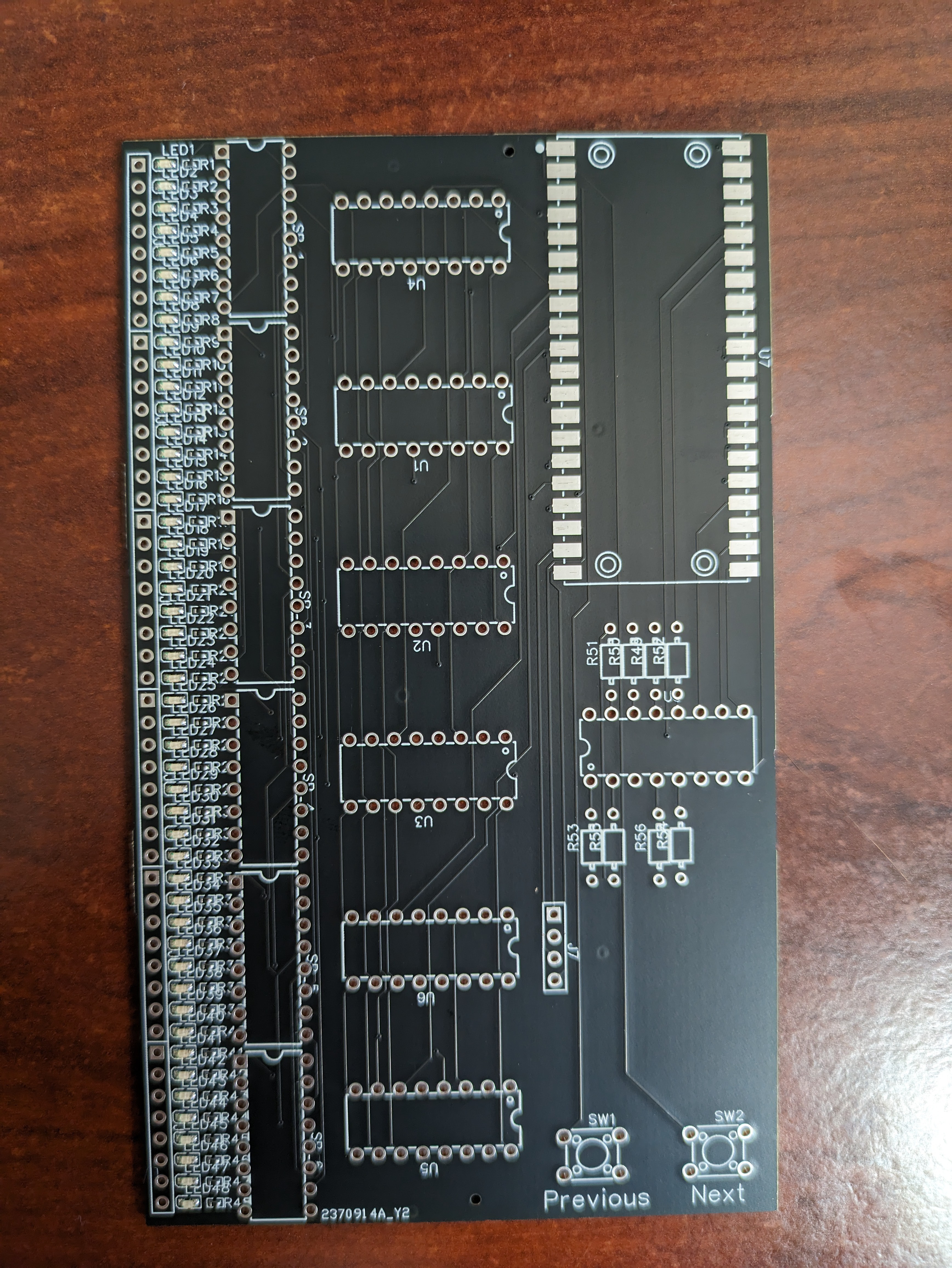
![]()
![]()
-
Awaiting Boards from Far Off Lands
08/30/2023 at 12:20 • 2 commentsThere's no way I'm going to be able to hand solder 96 tiny SMD components.
This is a direct quote from my brain.
I watch enough YouTube to know that there are a handful of PCB houses on the planet that want my business and are willing to accept my first attempt at PCB design and dutifully execute the details of my Gerber Baby files, pick and place spreadsheet and BOM. Terrifying.
The boards should arrive tomorrow and I'm very excited about it. Just holding a PCB (let alone a stack of them) that I designed is going to be a thrill. I haven't made a PCB since high school.
That being said, I will be astonished if this project works on the first try. Yes, I checked and double checked my connections and whatnot. I did (sort of) prototype the circuitry on a breadboard. But, I fully expect something to be terribly wrong and that debugging will take a while.
I'll be sure to keep you posted.
The Resistorganizer
Managing resistors is a chore. Well, with the Resistorganizer, you can just jam your loose resistors into a breadboard and be done with it.
 Mike
Mike