Sebastian
-
System Design
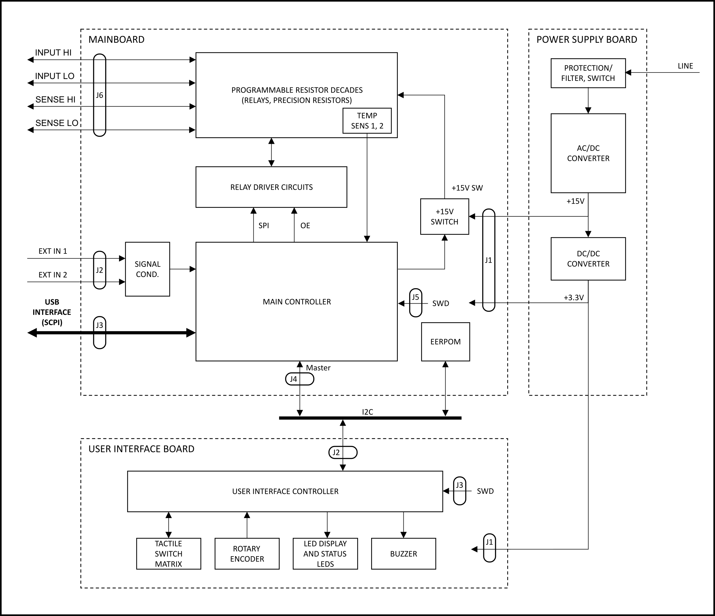
08/10/2023 at 18:22 • 0 commentsThe following block diagram provides an overview of the different circuit groups of each functional block, their internal connections and external interfaces.
![]()
Block diagram of the programmable decade resistor
The Programmable Decade Resistor consists of three main functional blocks:
- Power supply (Power Supply Board)
- Programmable decades, control and driver circuits (Mainboard)
- User Interface (User Interface Board)
The power supply board uses an off-the-shelve AC/DC converter to provide a +15V rail. The +15V rail powers the relays on the mainboard as well as a DC/DC converter. A single DC/DC converter generates a +3.3V supply for both the mainboard and the UI board, including the LED display. The power rails are earth-referenced. (Nevertheless, the inputs of the Programmable Decade Resistor are floating thanks to the isolation provided by the relays.)
The mainboard’s main controller contains the business logic to control the relays, read the external inputs and run the USB and user interfaces. The main controller communicates with the User Interface Board over I2C which handles the multiplexing of the alphanumeric LED display, scans the switch matrix, decodes the signals of the rotary encoder and drives the buzzer.
Next steps
The next post in this series takes a more detailed look at the mainboard.
-
How to improve the accuracy
08/05/2023 at 08:08 • 0 commentsNow that we have a calibrated programmable resistance decade, we can try to make the programmable decade resistor more accuracte - for higher resistance values. Actually, the idea behind that is trivial.
The idea
I'd like to start with an example in which we set a resistance value of Rset = 100.000 kΩ. (Let's not worry about temp drift, contact resistance etc.) In my case all resistors have a specified tolerance of 0.1. So we'd expect a resistance somewhere in the range of
Let's assume we estimated a resistance of Rset = 99.952 kΩ based on the calibration values. Now it's pretty obvious that we can use the lower two decades to add some additional resistance - 40 Ω from the second decade and 8 Ω from the first decade should do the trick. And with 0.1 % resistors we know that we'll achieve a value very, very close to 48 Ω. The actual setpoint that I will call the hardware setpoint has now become (Rhwset = 100.048 kΩ).
But care must be taken: In a more generalized sense the lower decades deviate from the theoretical value as well due to their tolerance. Had I chosen an estimated resistance Rest > 100.000 kΩ, it would have been not only a little more paperwork, but we would have ended up with a hardware setpoint below 100.000 kΩ, e. g. Rhwset = 99,910 Ω. Now it's easy to see that not only the highest decade might introduce a relevant error, but also multiple lower decades: Decade 4 (i. e. the fifth decade) could deviate by 90 Ω, decade 3 by 9 Ω and decade 2 by 0.9 Ω.
A simple, but unpractical approach
A simple approach for calculating the optimal hardware setpoint would be to use brute force and set up a look-up table that keeps the hardware setpoint in memory for any given setpoint. Certainly, such a look-up table can be accessed very quickly. But even on a computer a completely non-optimized approach for generating the look-up table can be rather time consuming. Whereas memory usage isn't a concern in that case, with microcontrollers this would be a completly different story: Good luck finding a (cheap) microcontroller with >4 MByte of Flash memory (1M datapoints with 4 Byte each if we are talking 6 decades). Also, the look-up table would have to be re-calculated whenever the programmable decade resistor is calibrated and this would take really long on a microcontroller.
In many cases we'd get away with such a lazy approach, but not this time. We need an algorithm that uses the current calibration values as an input and is able to narrow down the solution space in a way that allows for calculation in real time: Branch and bound.
Branch and bound
The obvious idea is to start the selection process at the highest decade. In our previous example we wanted to achieve Rset = 100.000 kΩ. With a tolerance of the resistors of 0.1% we can be sure that decade 5 has to be either a "1" (100.000 kΩ) or a "0" (0 Ω). If option "1" results in a resistance value greater than the setpoint, then we don't have to try to add any more resistance - this already would be the best we can do with this option. If it is below, then we apply the algorithm again, but now limited to the 5 lower decades and with the remaining Ohms as the new target. After that we repeat for option "0" and ultimately figure out who the winner was.
A few notes:
- The algorithm described can be implemented fairly easily with recursion. A good thing: The recursion depth is limited by the (fixed) number of decades, so that shouldn't become a problem if done properly
- It's the resistors' tolerances that decides which options have to be checked
- Eliminate as many of the options as required to reach the performance goals while factoring in the constraints imposed by the tolerances of the resistors
- For obvious reasons the accuracy of the calibration directly impacts the results of this approach
- The algorithm will achieve benefits for larger resistance values only
As for the calibration procedure, I'll share the results of this optimization in a future log.
Next steps
After many log entries about specific design decisions regarding the decade resistor itself it's time to discuss the system design.
-
The calibration procedure
08/02/2023 at 20:20 • 0 commentsIn the last post we had a look at the impact of the contact resistance on the decade resistor, especially for short circuits. This time I want to address the question whether we can make the resistor decade more accurate, despite the fact that the design doesn't feature any mechanism (e. g. potentiometer) to adjust resistance values. The short answer: Yes, partially. But first things first.
Inspiration
Let's have a look at another example of a programmable resistor: The Fluke 5450A is a resistance calibrator from the 80's (or so) that uses fancy precision resistors and relays to provide 17 different resistance values. It lacks any adjustment options too - stability is most important for a calibrator. Instead, the calibrator displays a calibrated value of the currently selected resistance that can be programmed by a calibration lab. This is an idea I'd like to adopt. Given the required equipment, performing the calibration of 17 resistance values isn't that big of a deal, doing it for each of the 1,000,000 resistance values of the programmable decade resistor, however, is a non-starter.
In contrast a reasonable approach would be to calibrate the decade individually and then calculate an estimate of the total resistance. This approach requires a closer look at the contact resistance of the relays (again) and other "parasitic" resistances in the signal path.
Calibration procedure
The basic idea of the calibration procedure is as follows:
- Estimate the average contact resistance. To do that:
- Short all decades avoiding the bypass relays
- Measure the resistance at the input of the programmable resistor
- Calculate the average by dividing the measured value by the number of relays in the signal path.
- Determine the calibration values of all 9 resistance values ≠0 Ω of each decade individually, while keeping the other decades shorted. The bypass relays could be used, but it might be easier not to. For a total of 6 decades there will be 54 additional calibration values.
- Set up the resistance value
- Measure the resistance at the input of the programmable resistor
- Determine the number of relays in the signal path
- Subtract the sum of the contact resistances of those relays from the measured value
In step 1 we assume that the contact resistance is significantly larger than other “parasitic” resistances – like the PCB traces, the wires to the terminals, their contact resistance and so on. Having a large number of relays in the signal path during the measurement – by not using the bypass relays – makes sure that the assumption is valid, at least to some extent.
Estimation of the total resistance
Now, when we want to estimate the resistance of any given combination of the decade, we do the following:
- Determine the theoretical resistance value by adding up the calibration values of all 6 decades according to the selected total resistance
- Determine the number of relays in the signal path
- Add the contact resistance according to the current switch state to the resistance value calculated in first step
For obvious reasons this approach won’t be perfect. In a future post I'll do a comparison between the estimated values and the measured values for a few exemplary resistance values.
Next steps
With the calibration constants determined, we now have to find a solution to improve the accuracy of the programmable decade resistor. Let's see what we can do and how we do it despite the fact that we don't have any potentiometers at our disposal.
- Estimate the average contact resistance. To do that:
-
The problem with the contact resistance
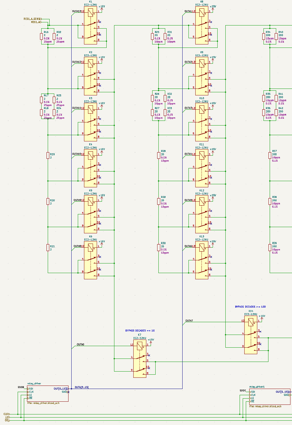
07/31/2023 at 12:12 • 0 commentsIn previous posts we already discussed different topology options for the decade resistor. Let's refresh our memory with an excerpt of the actual schematic showing the topology chosen for this project:
![]()
Excerpt of the schematics. Decades 0 and 1 shown. In contrast to previous schematics I included relays instead of simple switch symbols in order to look at different aspects of switching - in particular the effect of the contact resistance of the relays, which impacts the performance of the decade resistor, not only, but especially when a decade is shorted.
Bypassing upper decades
In order to improve the accuracy of the programmable decade resistor at low resistance values, additional switches can be introduced. These switches would bypass all higher decades that otherwise would be in series (although shorted), and therefore reduce the error caused by contact resistance. For the intended application it's probably not justified to add such bypass switches after decades having too large of a resistance value, like 10 kΩ and up, because then
- the rather low contact resistance of the relays (typically well below 100 mΩ) is below the tolerance of the resistors and
- the number of contacts bypassed decreases further and further, deminishing the returns.
With these considerations I decided to use such bypasses after each of the three lower decades only, increasing the total number of relays by three. Two of those relays (K7, K14) can be found in the excerpt of the schematics (see above).
Shorting a decade
When shorting the first decade (i. e. selecting 0 Ω) the simplest approach would be to just close relays K1, K2 and K7 (bypass). However, the resistance could be reduced by paralleling one or more taps of the resistor network. But how large would the effect be? And is it really worth it? Short answer: No. Long answer below.
I did the math assuming a contact resistance of 40 mΩ (both relay poles in parallel). The values take into account the resistance values of resistors connected in parallel with a closed switch, resulting in these odd values shown below:
Relays closed Resistance
(Ω)Absolute difference
(Ω)Relative difference
(ppm)K1, K2, K7 0.1184615385 <baseline> <baseline> K1, K2, K3, K7 0.1176923077 -0.0007692308 -6493.506 K1, K2, K3, K4, K7 0.1176920230 -0.0007695154 -6495.909 K1, K2, K3, K4, K5, K7 0.1176920230 -0.0007695155 -6495.910 K1, K2, K3, K4, K5, K6, K7 0.1176920230 -0.0007695155 -6495.910 Theoretical resistance of the first decade when shorted using varying number of relays (10 decimal places) Closing relay K3 can reduce the resistance by 0.65%. This sounds like something, but it's not even a milli-ohm in absolute terms. Since the contact resistance of relays changes over time (and probably switch current etc.) the difference is absolutely irrelevant. Closing even more relays makes even less sense (due to the series resistance in the additional relay’s signal path). For the higher decades improvements would be only about 1/10, 1/100, 1/1,000, 1/10,000 and 1/100,000 of the values shown above.
On the other hand, closing additional relays causes more switching cycles and increases power dissipation that might support a temperature drift of the resistors (if non-latching relays are used).
And that's why I did not implement such a software "feature".
Next steps
We have a general idea of how to control the relays in order to achieve a certain nominal resistance value using the selected topology. We know the effect of the relays' contact resistances on shorted decades. But what is the actual resistance that is selected - be it a short or any other value? How can we make sure that the actual resistance is as close to the nominal resistance as possible? That's what we have to look into in the next log entries.
-
Power Rating (2): Derating and more
07/27/2023 at 15:34 • 0 commentsIn the last log entry we discussed how to calculate the power rating of the programmable decade resistor. We assumed that the decade resistor is made of resistors with the same power rating – in reality this might not be the case. Also, it might be a good thing to derate the resistors a bit. So let’s see what the implications are.
Resistor power rating and derating
In this particular implementation, the assumption of equal power ratings of all resistors is only true for the upper five decades-the first decade uses resistors with only P00 = 0.125 W instead of 0.4 W due to limited availability of higher rated ones. Now the equation looks like this:
That's why we'd have to check the first decade (n = 0) as well, whenever the second decade (m = 1) is the highest non-zero decade.
Derating of the resistors
There is another aspect that might actually help us out: Derating. It's a good idea to derate the resistors. This not only limits the temperature and therefore improves (long- and shortterm-) stability, but also gives some additional headroom for an accidental overcurrent situation. (A warning: I hope that the comparatively wide traces help to cool the resistors, so that they don't suffer a little less. However, utilizing the maximum or even the mildly derated power dissipation capability will likely result in some resistance drift. If you want to minimize that effect, overspec the resistors like ... a lot.)
The initial requirement for the programmable resistor was a power rating of Pmax,tot ≥ 0.5 W for all ranges. Since the power rating of a single decade is Pmax ≥ 2P0n (see table for a single decade in the previous log), we can derate the resistors from 0.4 W to 0.25 W (-37.5%) for all decades n ≥ 1 without compromising the goal.
Not so great: The first decade has to use 0.125 W resistors (due to availability of precision resistors, at least at the time of building the unit), making it impossible to achieve anything close to the inital goal of 0.5 W, even without derating. So would it at least possible not to limit the maximum current even more than the second decade does (while still allowing for some derating)? Yes, with a derating to 0.1 W (-20%) we get:
So no special checks for the first decade required anymore. Summed up:
Decade
nResistor power rating
P0n / WDerated resistor power rating
P0n,d / WDecade power rating
Pmax,n / W0 0.125 0.1 ≥ 0.2 1 .. 5 0.4 0.25 ≥ 0.5 Calculation of the limits
After all those considerations it's fairly simple to calculate the current, voltage and power limits:
- Determine the maximum allowable current: It's trivial to determine the highest decade h that is not shorted. Therefore the maximum current Imax,tot can be determined easily (see table for single decade in the previous log).
- Calculate the maximum allowable voltage: Umax,tot = R ⋅ Imax,tot
- Calculate the maximum allowable power dissipation: Pmax,tot = R ⋅ (Imax,tot)2
There might be other reasons to limit the current, voltage or power. A good example would be voltage limits imposed by the PCB's clearance/creepage distance between conductors of different potential.
Next steps
In the next log we will dive into the topic of switching the relays.
-
Power Rating (1): The basics
07/23/2023 at 17:53 • 0 commentsIn the last post we worked on some implementation details to consolidate the bill of material while improving the power rating of the decade resistor. However, we didn’t fully analyze the design regarding power dissipation.
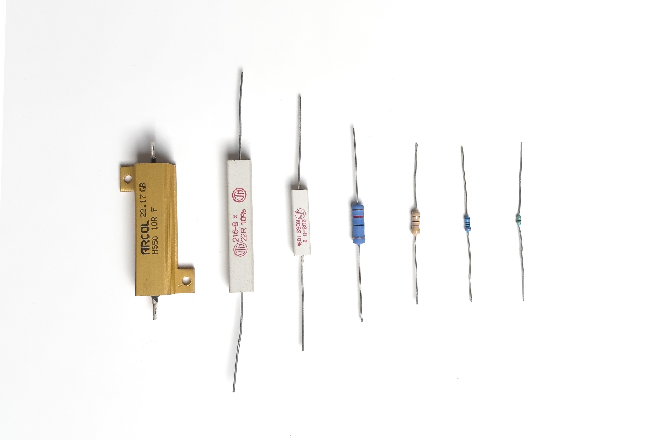
![]()
A bunch of (power/leaded) resistors with different power ratings
So let’s do that now and get some definitions out of the way:
n Decade n providing resistance values 0 Ω, 1⋅10n Ω to 2⋅10n Ω Rn Total resistance of decade n as set by the switches R0n Resistance of an individual resistor of decade n (in the example: R0n = 2 Ω) P0n Power rating of any individual resistor of decade n @ power rating Imax,n Maximum allowable current for decade n Pmax,n Maximum allowable power dissipation for decade n Umax,n Maximum allowable voltage for decade n Imax,tot Maximum allowable current for the programmable resistor (all decades) Pmax,tot Maximum allowable power dissipation for the programmable resistor (all decades) Umax,tot Maximum allowable voltage for the programmable resistor (all decades) Note: I don't think that hackaday supports inline LaTeX. Please let me know if it does.
The definitions imply that we use identical resistors throughout a decade. For this post we also assume that the power rating of all resistors are the same. In reality this is not the case. That’s one of the reasons for part 2 of this post…
Exemplary calculation for the first decade
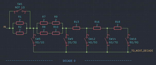
![]()
First decade (n=0) Let Imax,0 flow into the first decade (n = 0, R00 = 2 Ω) with all switches open except for SW12. The resulting resistance is R0 = 5 Ω = 2.5 R00. Then:
- a current of 0.5 Imax,0 will flow through the resistors with the designators R1, R2, R7, R8, R9, R10 (see schematic above)
- a current of Imax,0 will flow through the resistor with the reference R13
Hence Imax,0 is defined by the current that flows through R13 when the dissipated power equals its power rating:
The maximum total power dissipation of the decade is the sum of the power dissipation of the individual resistors (at their respective current). Accordingly:
The maximum allowable voltage is:
Table for decade n
To generalize the example shown above, here's a table showing the results for all resistance values in tabular form.
R0 / R0n Imax,n Pmax,n Umax,n 0 limited by relays limited by relays limited by relays 1 2 I0n 2 P0n sqrt(P0n ⋅ R0n) 2 2 I0n 4 P0n 2 sqrt(P0n ⋅ R0n) 3 2 I0n 6 P0n 3 sqrt(P0n ⋅ R0n) 4 I0n 2 P0n 2 sqrt(P0n ⋅ R0n) 5 I0n 2.5 P0n 2.5 sqrt(P0n ⋅ R0n) 6 I0n 3 P0n 3 sqrt(P0n ⋅ R0n) 7 I0n 3.5 P0n 3.5 sqrt(P0n ⋅ R0n) 8 I0n 4 P0n 4 sqrt(P0n ⋅ R0n) 9 I0n 4.5 P0n 4.5 sqrt(P0n ⋅ R0n) Considerations for multi-decade resistors
If the power rating of the individual resistors in the programmable resistor are identical, the maximum current Imax,tot is limited by the decade with the highest resistance. To prove this, we show that the largest maximum permissible current of a higher decade m is still less than the smallest maximum permissible current of a lower decade n < m.
1. Determine the smallest maximum permissible current for the lower decade n
With the total resistance of a decade of Rn = ln ⋅ R0n, the smallest maximum current for decade n results for ln > 3 (see table for sigle decade). Therefore:
2. Determine the largest maximum permissible current for the higher decade m
With the total resistance of a decade of Rm = lm ⋅ R0m, the largest maximum current for decade m results for lm in {1, 2, 3} (see table for sigle decade). Therefore:
3. Utilize the assumptions
If m is the next-higher decade (i. e. m = n + 1), the resistor value for decade m is ten times larger than for decade n
Also, we assumed that the power ratings of all resistors all equal:
4. Bringing it all together
Therefore, under these assumptions the power rating of the programmable resistor is limited by the highest non-zero decade.
Conclusion and next steps
The main take-aways are:
- The maximum power rating of a decade can vary depending on the selected resistance value. Therefore it makes sense to calculate and display the applicable power rating for the resistance value set by the user instead of having a fixed rating for all resistance settings
- Using the topology and applying the aforementioned assumptions (in particular: same power rating for all resistors), the power rating is at least two times the power rating of the individual resistors
- Then the power rating of the programmable resistor is limited by the highest non-zero decade
The next post in this series will focus on the actual component selection and the implications on the subject of the power rating of the programmable decade resistor.
-
Topology (2)
07/23/2023 at 13:12 • 0 commentsIn the last log entry we selected a resistor network and switch topology that suits the needs of this programmable resistor. Now we will apply simple optimizations that allow an effective and cost-efficient implementation.
![]()
Optimizing the bill of material
In order to reduce the number of different components the single 1 Ω is replaced by two parallel 2 Ω resistors. As a very welcome side effect this doubles the power rating for the setting 1 Ω. This is very helpful, because the lower the selected resistance value of the decade, the fewer resistors the power dissipation is distributed over.
For this very reason it can be very beneficial to increase the power dissipation capabilities of the first 2 Ω increment as well - otherwise the corresponding resistor would become the bottleneck in regards to power dissipation. We can achieve this by replacing the single 2 Ω resistor by four 2 Ω resistors, implementing a parallel connection of two series connections. Due to the quantity discount offered by distributors like digikey and mouser, using a total of 9 identical resistors isn't quite as bad as the number might suggest. Therefore the final design looks like that:
![]()
Next steps
Now the question is: What are the current handling and total power dissipation capabilities and the maximum allowable voltage for both an individual decade and the programmable resistor decade, as the answer may vary for different resistance settings? Well, we will discuss that in the next posts.
-
Topology (1)
07/20/2023 at 19:09 • 0 commentsIn this post I want to share how I selected a suitable topology for the resistor network that will be the core of the programmable decade resistor. Although I did some online “research”, the following criteria determined my choices:
- Switch selection: The switches shall be operated electrically. Solid state switches are great for many applications, but tend to have undesired characteristics. In this case, electromagnetic (signal) relays are a logical choice, because they provide
- isolation between the control circuit and the external application circuit,
- a fairly low contact resistance and drift over temperature and
- reasonably high current switching and carrying capabilities
- while maintaining low leakage currents.
- Accuracy: Each relay contact in the signal path will introduce an additional resistance (and potentially thermal EMF issues, that I won’t consider here). This is a good reason to minimize the number of switches in the signal path considering all resistance values of the decade resistor. Besides that it might be desireable to keep the number of relays in the signal path as constant as possible so that the variation of the error caused by the relays is better controlled.
- Cost: Relays mostly have a very limited number of poles and throws. Therefore the number of relays required will be rather high and quality relays are expensive. The topology should therefore minimize the total number of switches required. Also, the cost of precision resistors depend on the required resistance of the resistor and quantity per value.
- Parts availability: The availability of precision resistors with the specified resistance values and other characteristics is critical.
There are many more aspects that could have been considered in greater detail (like frequency response). However, the criteria mentioned above helped me to disregard some topologies and focus on the two that I describe below. To make my life easier, I will use the resistance values required for the decade n = 0 that provides the resistance values 0 Ω, 1⋅10^n Ω to 9⋅10^n Ω. The reader may apply a different n as well.
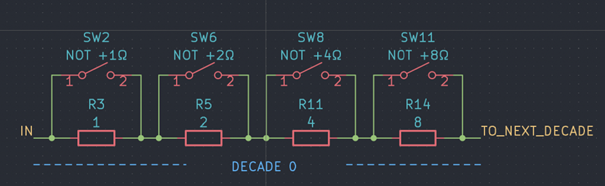
Topology A
![]()
Topology A
This variant uses four resistors connected in series, with 1 Ω, 2 Ω, 3 Ω and 4 Ω of resistance respectively. Each resistor can be shorted with a switch, hence presenting 16 valid switch combinations/resistance values. In practice, five or six of those combinations could remain mostly unused: 10 Ω, 11 Ω to 15 Ω. It’s worth noting that with these switches alone it is not possible to open the circuit, hence increasing the total number of relays in a multi-decade resistor by one if that feature is called for.
Although this approach minimizes the total number of switches, the number of switches in the signal path can become relatively high. The worst case situation would be a short: For a 6-decade resistor the minimum resistance would roughly equal the contact resistances of 24 relays (or 25 if you count the additional breaker) connected in series, though each in parallel to the respective shorted resistor. Depending on the contact resistance of the switches this introduces an error that might be unacceptable for some applications, especially for decade(s) with generally low resistance values. Maybe worse – the additional contact resistance may vary with the selected resistance value: For example, to select 7Ω, exactly one switch is closed (SW 11). In contrast, only closing all four switches will short the decade.
Although it would be fine to (at least) use this topology for the upper decades I wanted to keep all decades the same. With the disadvantages described above, I decided against using this topology at all.
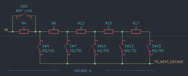
Topology B
![]()
Topology B
In variant B a total of five resistors (1 Ω, 4x 2 Ω) are connected in series, complemented by six switches. Closing one of the five switches SW4, SW7, SW10, SW13 and SW15 while switch SW3 is closed selects 0 Ω, 2 Ω, 4 Ω, 6 Ω and 8 Ω of resistance respectively. Leaving SW3 open instead adds 1 Ω to these values.This topology requires six switches per decade – two more than variant A – and five instead of four resistors. But now, only either one (for odd resistance values) or two (for even resistance values) switches are in the signal path, reducing the maximum total contact resistance by a factor of 2. Not only that, the (maximum) variation of the contact resistance is lowered as well. A separate “breaker” to open the circuit is not required.
As a side note: My "vintage" Siemens decade resistor box that I bought not too long ago uses this exact topology as I discovered after designing the device. However, because of the fancy rotary switches, the schematic looks way more complicated…
Next steps
In the next post I’ll highlight (very) simple, but effective optimization opportunities that will make the implementation (not only) more cost-efficient. Closely related to this: The power rating of the decade resistor.
- Switch selection: The switches shall be operated electrically. Solid state switches are great for many applications, but tend to have undesired characteristics. In this case, electromagnetic (signal) relays are a logical choice, because they provide