-
Wiring diagram
02/04/2024 at 13:29 • 0 commentsIt's great to see several people have built their own versions based on my design. If you've built your own, please send me a picture, I'd love to see it!
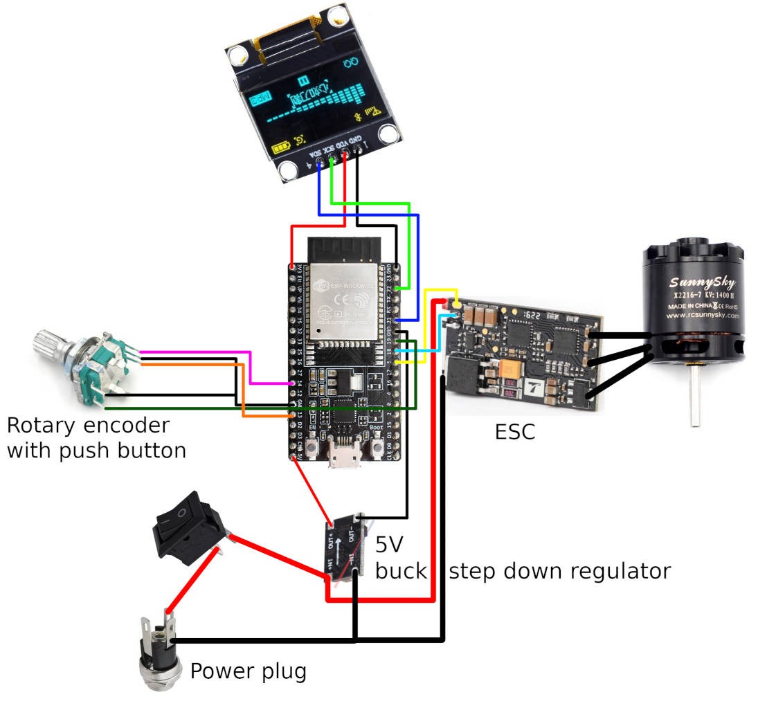
I've gotten several requests for a wiring diagram, so here it is. I had naively thought the wiring is self-explanatory, but considering how long it took me to make this diagram, I was probably wrong. Please forgive the amateurish drawing. I hope it helps.
Note that I did not hook up the ESC's GND serial connection. There's no good reason for this, I just ran out of space. It works fine, but you could hook it up if you want to.
![]()
-
YouTube video
09/04/2023 at 06:15 • 0 commentsThis project got an unexpected amount of attention, so I made a video overview. I followed the Hackaday Prize 2023 guidelines and kept it under 5 minutes, though I probably won't qualify for the contest because I don't have enough project log entries (and not enough time to make more).
-
It's working!
07/21/2023 at 13:21 • 0 comments![Star Wars Its Working GIF - Star Wars Its Working Scream - Discover & Share GIFs]()
To finish up the build, I 3D printed a plate with screw holes to attach it to the brushless motor and more screw holes to clamp down a PCB. I also 3D printed a cylinder to surround the spinny bits and laser cut a lid from acrylic. The cylinder also contains a moat to collect any excess fluid that drips down the sides. I used a piece of acrylic someone left on the scrap pile at my local hacker space. I think it's been there for a long time, because the protective foil did not want to come off cleanly. In my impatience, I ended up scratching the acrylic quite a lot.
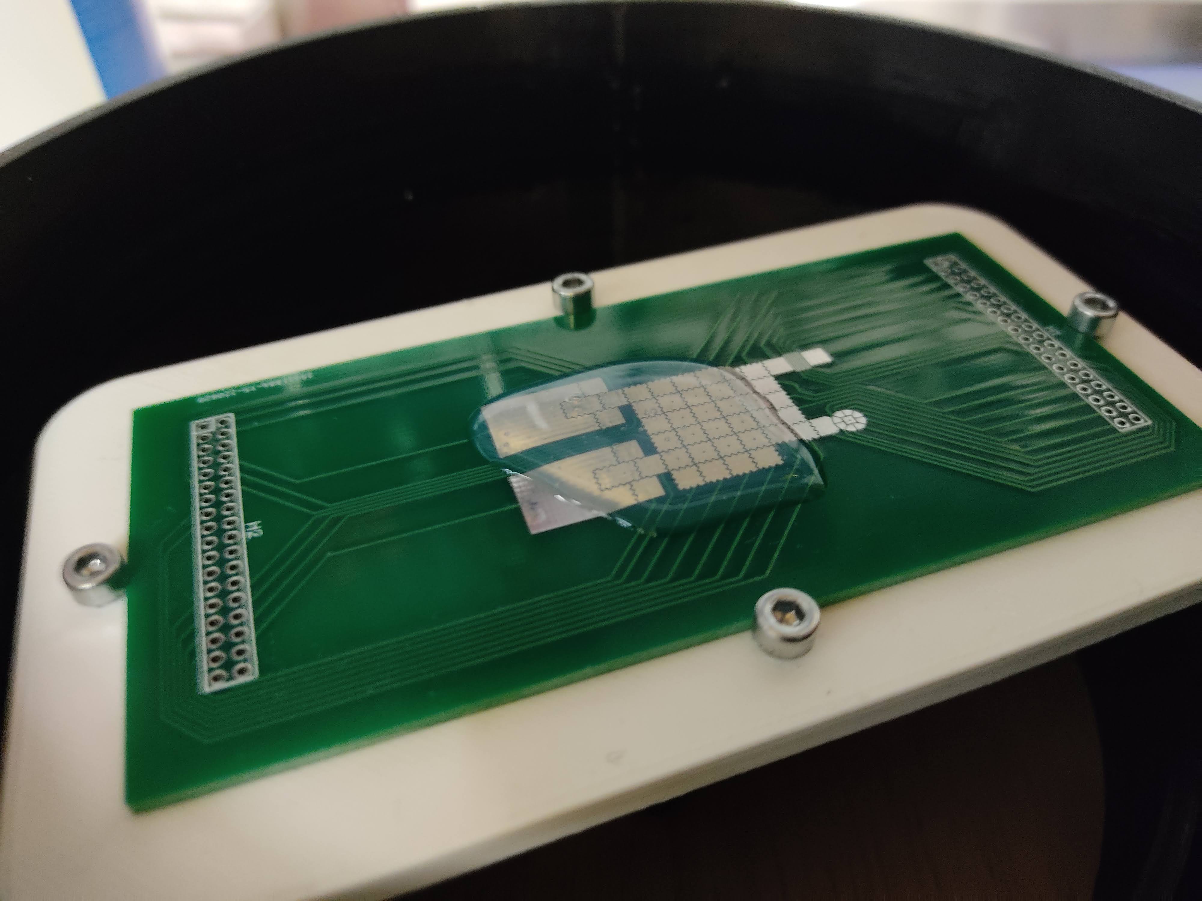
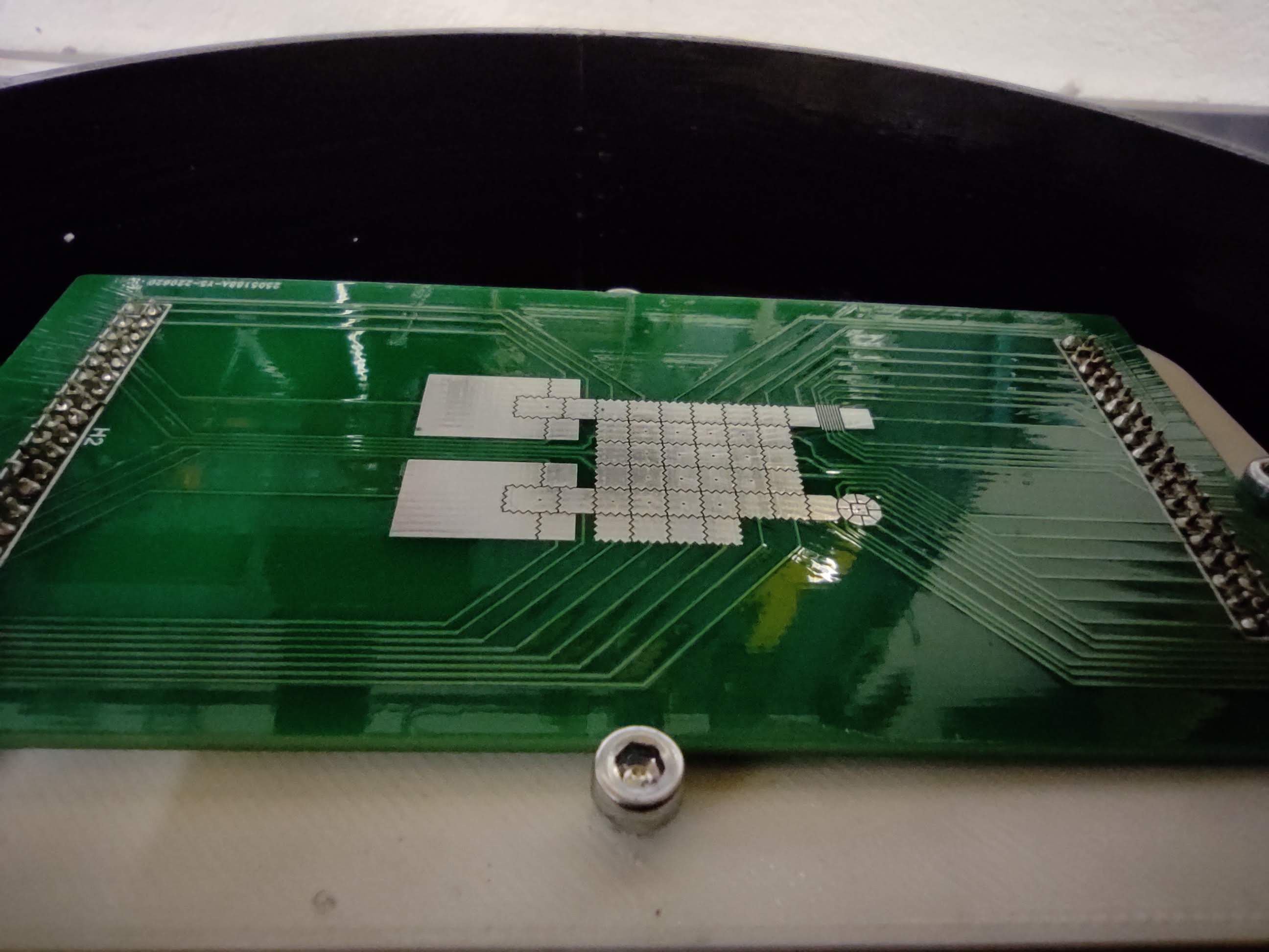
As a first test, I mixed pourable silicone rubber and put some of it on the middle of a flat PCB. This is very viscous stuff (shore 40), so I was curious to see how thin and evenly distributed it was going to end up after spinning.
Before and after:
![]()
![]()
A great success!
According to the theory, the thickness of the liquid layer should be proportional to the inverse of the square root of the spin speed. I wish I had a way to measure the thickness. Maybe someday I'll build a spectroscope setup and use interferometry to measure thickness down to the nanometer range, like in this awesome video by Sam Zeloof. I wonder how affordable a white light interferometry setup would be.
After I recorded the video, I 3D printed a hinge to keep the lid in place. I also added foam padding around the rim and to the underside of the enclosure to dampen the vibrations. Now I don't have to hold it down anymore when it's running at 10000 RPM :) I also noticed the white plate I printed to hold the PCB was a bit warped, making it unbalanced. I printed another one that turned out better. This reduced the vibrations quite a lot.
You might've noticed in the video that the screens acts glitchy and the ESC startup sounds play. It seems that setting the throttle to 0 on the ESC doesn't let it spin down but actively brakes the motor. This create a spike in the power circuit that can sometimes reset the microcontroller. This is bad and can eventually break some components. I don't need active breaking, so I should really figure out a way to let it spin down freely. Or at least slowly ramp down the target RPM or something. [EDIT: Thanks to @Mathieu Lacage for letting me know this can be done using this BLheli configurator tool]
This thing has quite a lot of power! I can feel wind coming out from small gaps in the foam padding around the lid. I guess I shouldn't be surprised, given I'm using a motor that was designed to be used in a quadcopter.
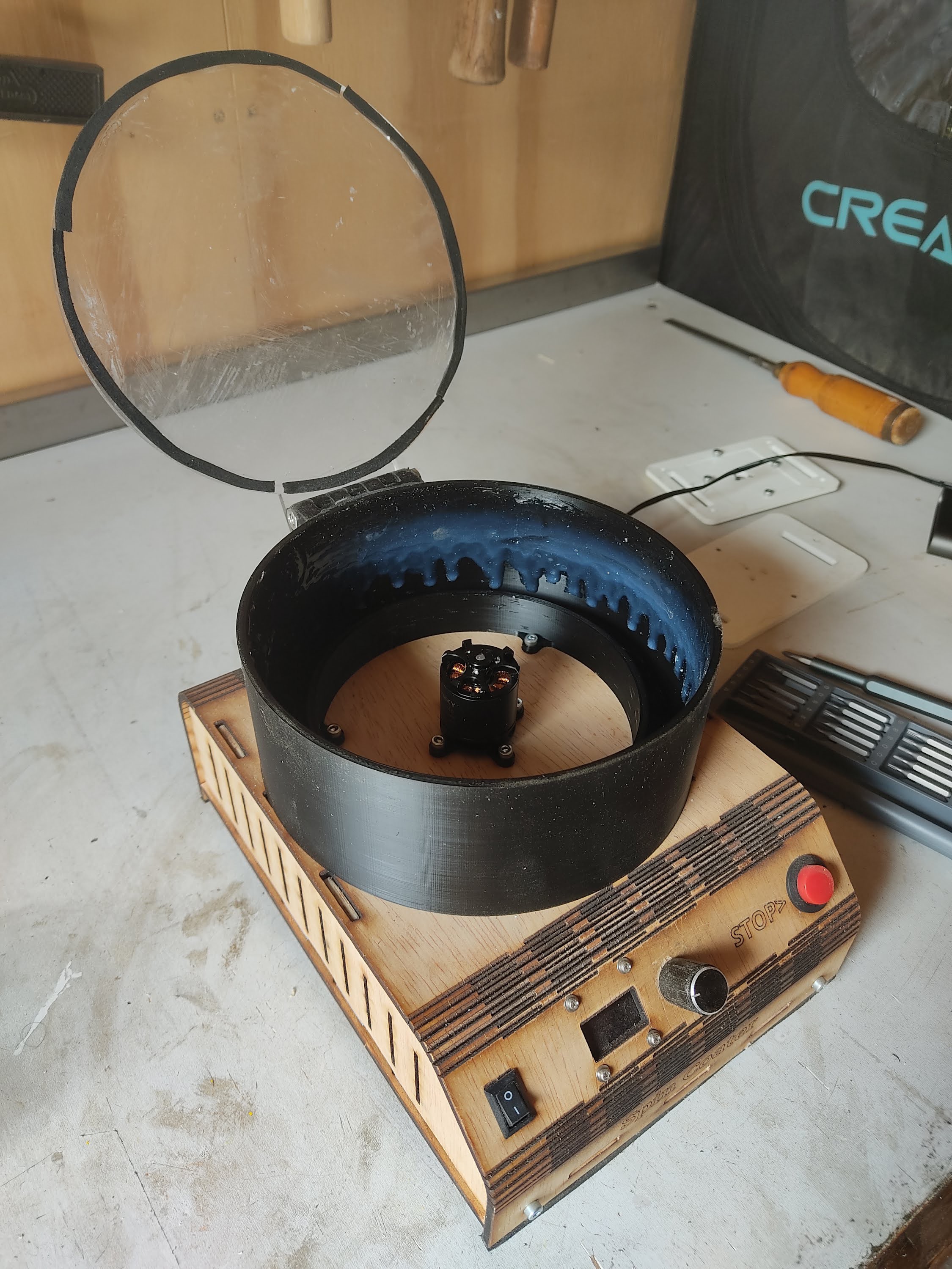
The picture below was taken quite a bit later, after I got into woodworking. That's why it's covered in sawdust.
![]()
If I were to make a version 2, I'd tidy up the electronics and make the whole thing a lot smaller. Maybe add some weight to dampen the vibrations further. I'd also remove the red stop button that's not actually connected to anything (I ended up just using the rotary knob as an emergency stop button). For now, this version is actually working great and fits my needs. Hurray for the DIY community!
-
Speeeeeeeed!
07/21/2023 at 12:37 • 0 comments![Jeremy Clarkson Driving an Ariel Atom | Know Your Meme]()
I FINALLY got the motor PID control working!
Like I mentioned in the project description, there's a few different ways to do PID speed control on brushless motors, depending on the ESC hardware and firmware. I decided to use the Dshot protocol to send throttle commands to the ESC. I owe many thanks to Chris Landa who wrote an amazing guide on how the Dshot protocol works. Implementing the Dshot protocol using MicroPython was definitely a challenge, but thanks to Chris, I didn't have to reverse engineer the protocol first (which would have been a real pain, since I've never reverse engineered a digital protocol before).
I used the RMT module that's on the ESP32 to send the very short pulses necessary for the Dshot protocol. In theory, the same module could be used to implement bi-directional Dshot to receive telemetry (such as RPM) from the ESC. Sadly, eceiving pulses is currently not supported in MicroPython. I could write a separate module in C just for the receiving part and import as a MicroPython library, but I'd have to seriously brush up on my C skills. Instead, I decided to pick an older ESC that has an extra telemetry wire. The telemetry wire uses a separate protocol which seems to be poorly documented. Chris Landa thankfully posted a link to a PDF document from an rcGroups thread that has enough details to work with.
However, I just couldn't get it to work. I banged my head against the wall for days trying to find a bug in my code or an issue in the wiring. I bought a special connector to hook up the ESC to my PC so I could look at some settings in the BLHeli_32 firmware. At some point, a friend of mine was gracious enough to lend me his oscilloscope and teach me how to use it. I wanted to see what the signal coming over the telemetry wire looked like. So I hooked up the probe and started requesting telemetry data using Dshot, but nothing was coming over the telemetry wire. No signal at all. It was steady at a rock-solid +3.3V. I spent another day looking for a bug in my code, figuring I must not be requesting the telemetry data correctly.
After many sunken hours without progress, I went for a Hail Mary and ordered a different ESC that also had a telemetry wire. I had originally bought a SkyStars Slim40A Blheli_32 128K from AliExpress. I didn't have the patience left to wait another two weeks on shipping from China, so I bought a more expensive ESC (a T-Motor F35A) from a local shop with next-day delivery. To my surprise and great relief, it worked straight away. Turns out there was no flaw in my code, it was just a bad ESC. Such is the way of the hardware hacker doing it on the cheap. Oh well, at least I learned a thing or two about digital signal analysis along the way.
After some tuning of the PID values, the motor was humming away and staying at the specified RPM beautifully. To simulate the increased load when the chuck and spin plate would later be attached, I pushed my finger against the motor as it spun to increase friction. It's fun to feel the motor ramp up and down to maintain the target RPM.
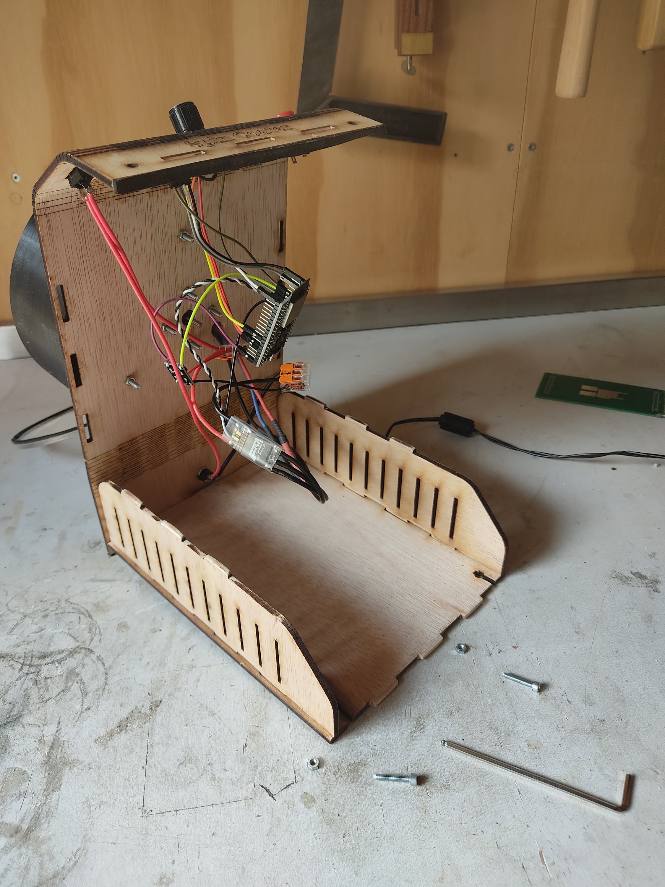
Here's a picture of the electronics inside the plywood enclosure. There's a lot of empty space and nothing is properly secured, but I figured it's fine for a prototype. Better to have things come undone sometimes than glue everything down only to find out you have to replace the ESC.
![]()
-
First GUI test
07/21/2023 at 11:31 • 0 commentsWhile waiting for the rest of the parts to arrive, I got started on the user interface. It's programmed using MicroPython running on an ESP32 dev board. I'm very comfortable with Python and had dabbled in MicroPython before, but this was definitely a challenge. Of course, I couldn't use any of the well-known GUI frameworks for Python because those are made to be used on desktop computers. So I had to start from scratch and write a very simple framework to let the user navigate through different screens. It was a lot of fun going back to basics. I ended up writing an update loop that runs different draw functions based on where the user currently is, kind of similar to how ReactJS works. The resulting interface is simple, but intuitive -- at least, I like to think so.
Here's a first test video. I hadn't written the code to communicate with the ESC yet, so the RPM values are always zero.
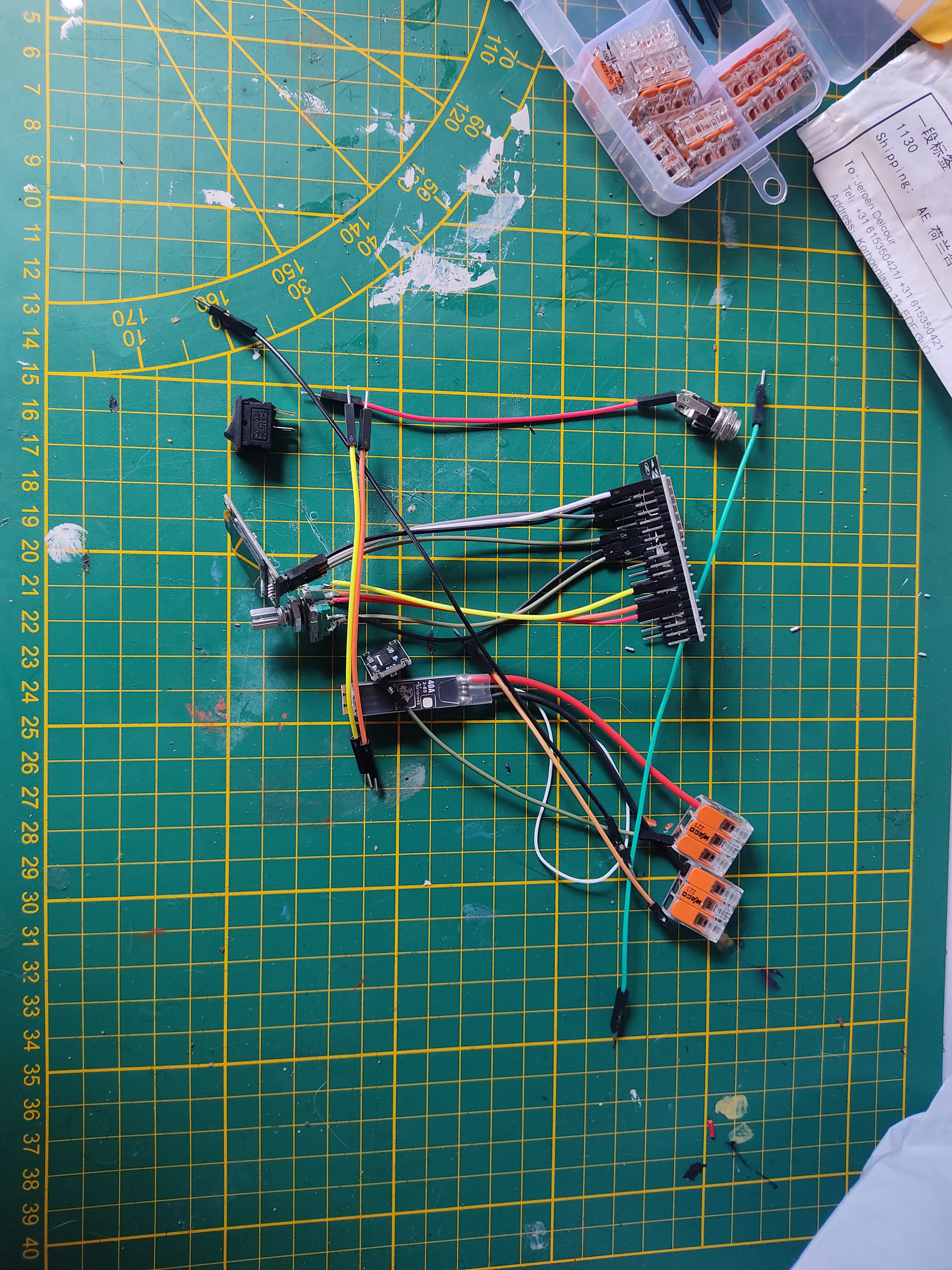
Here's a picture of all the electronic components roughly laid out in the way I want to connect them.
![]()
-
Designing and building the electronics enclosure
07/21/2023 at 11:04 • 0 commentsI decided to use plywood for the electronics enclosure, since I have access to a laser cutting at my local hacker space. Plywood is cheap, and the laser cutter is fast, so it'll let me prototype quickly and quickly build more if I need to. Using a laser cutting also gives me confidence that I can give the design enough stiffness and minimize vibrations.
Of course, I could just use a standard box with interlocking finger joints. But I wanted a design that gave me quick access to the inside, without having to undo a ton of screws. I also wanted to challenge myself and make it look more interesting then just a box. I ended up going with a design where the front, top, and back is made from a single curving piece. It's held in place using only 4 screws: 2 in the back and 2 in the front. To give it a little more rigidity, the top is held in place by the side pieces with small tenon joints that are loose enough to come undone easily when I need access. To open it up, all I need to do is remove the front two screws and lift up the top like the hood of a car. It's not the sturdiest design (and can be awkward to put back together), but it gives me easy access to the internals to fix any issues that undoubtedly will arise. Plus, I think it looks neat!
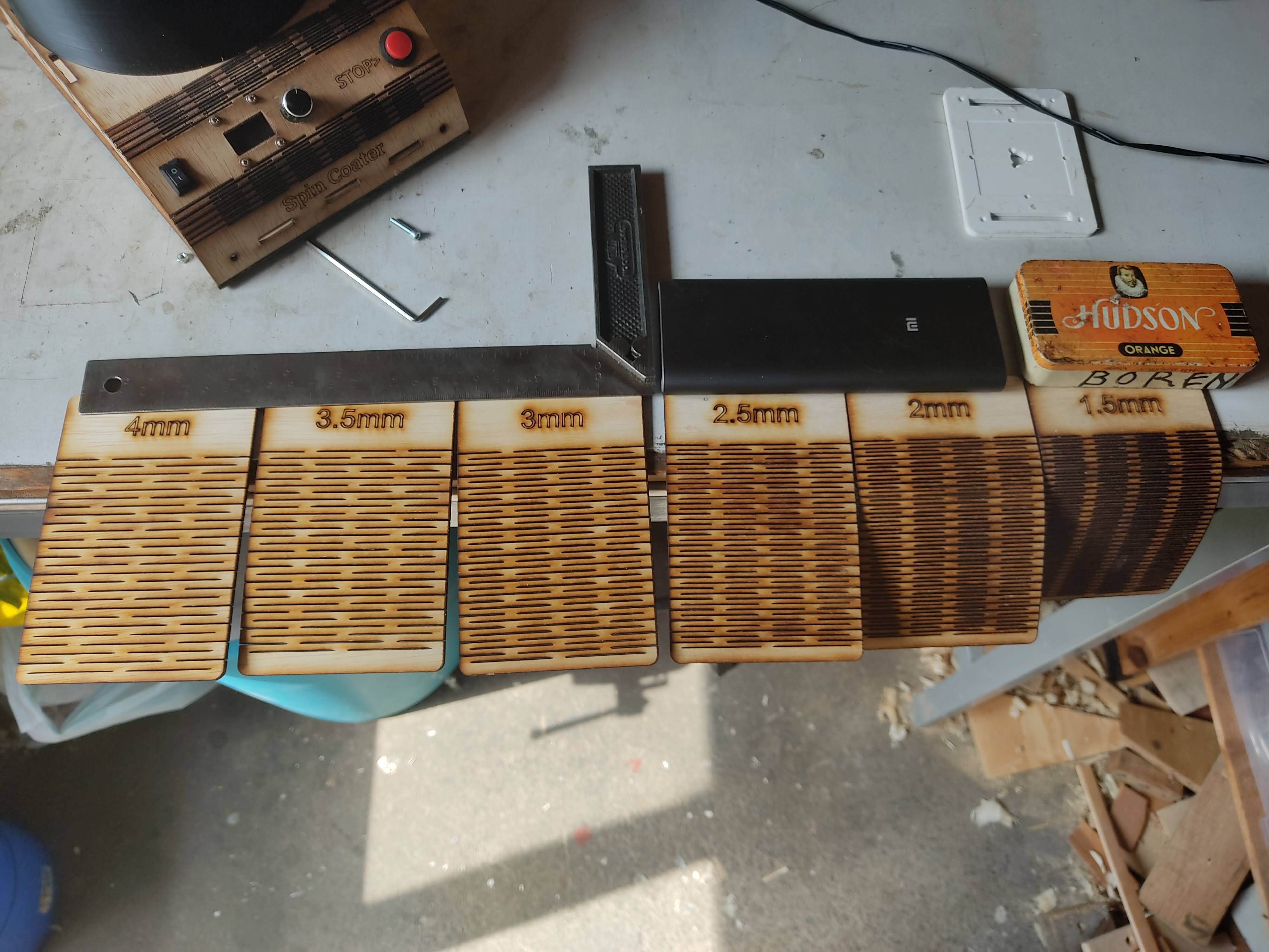
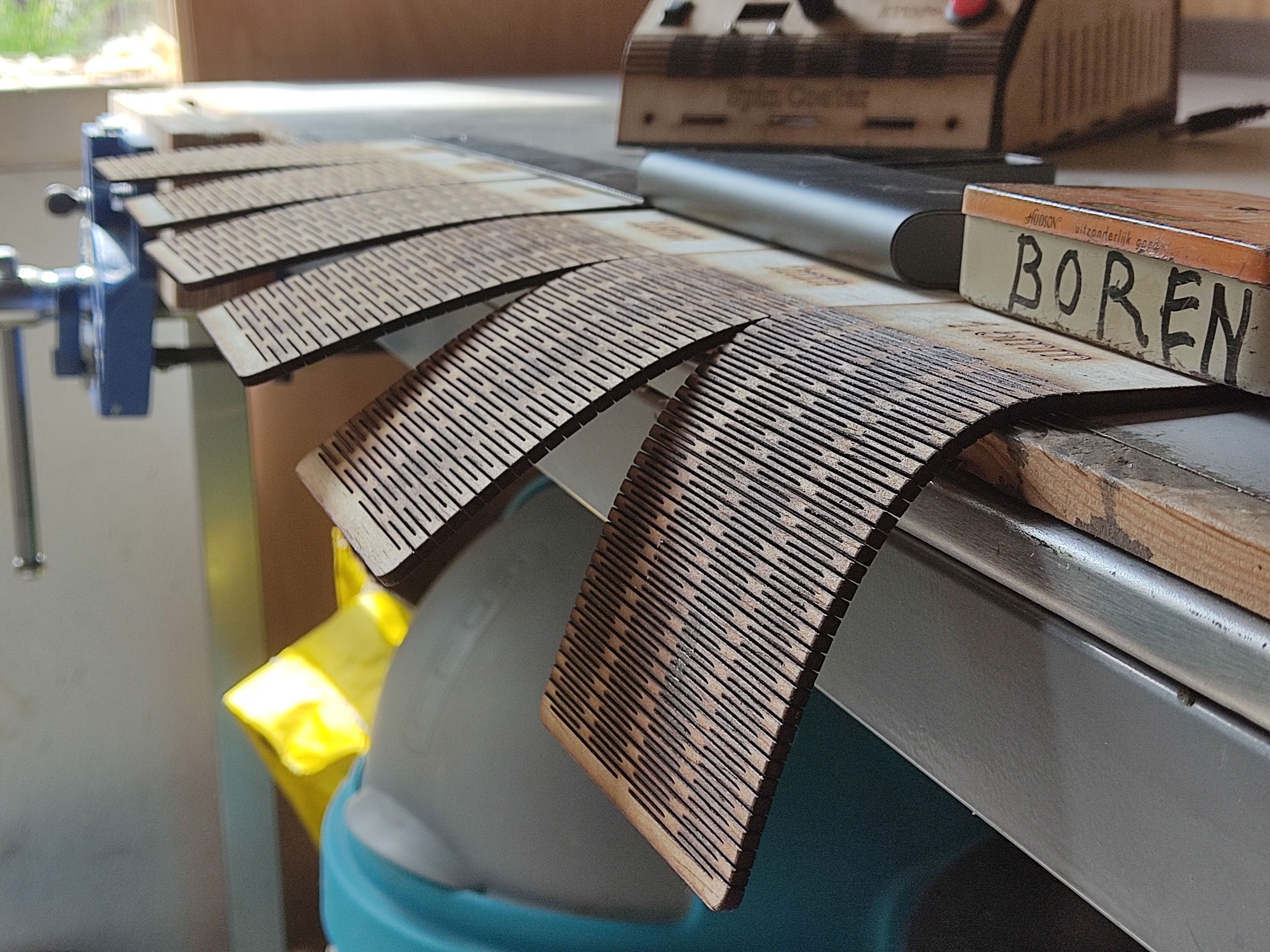
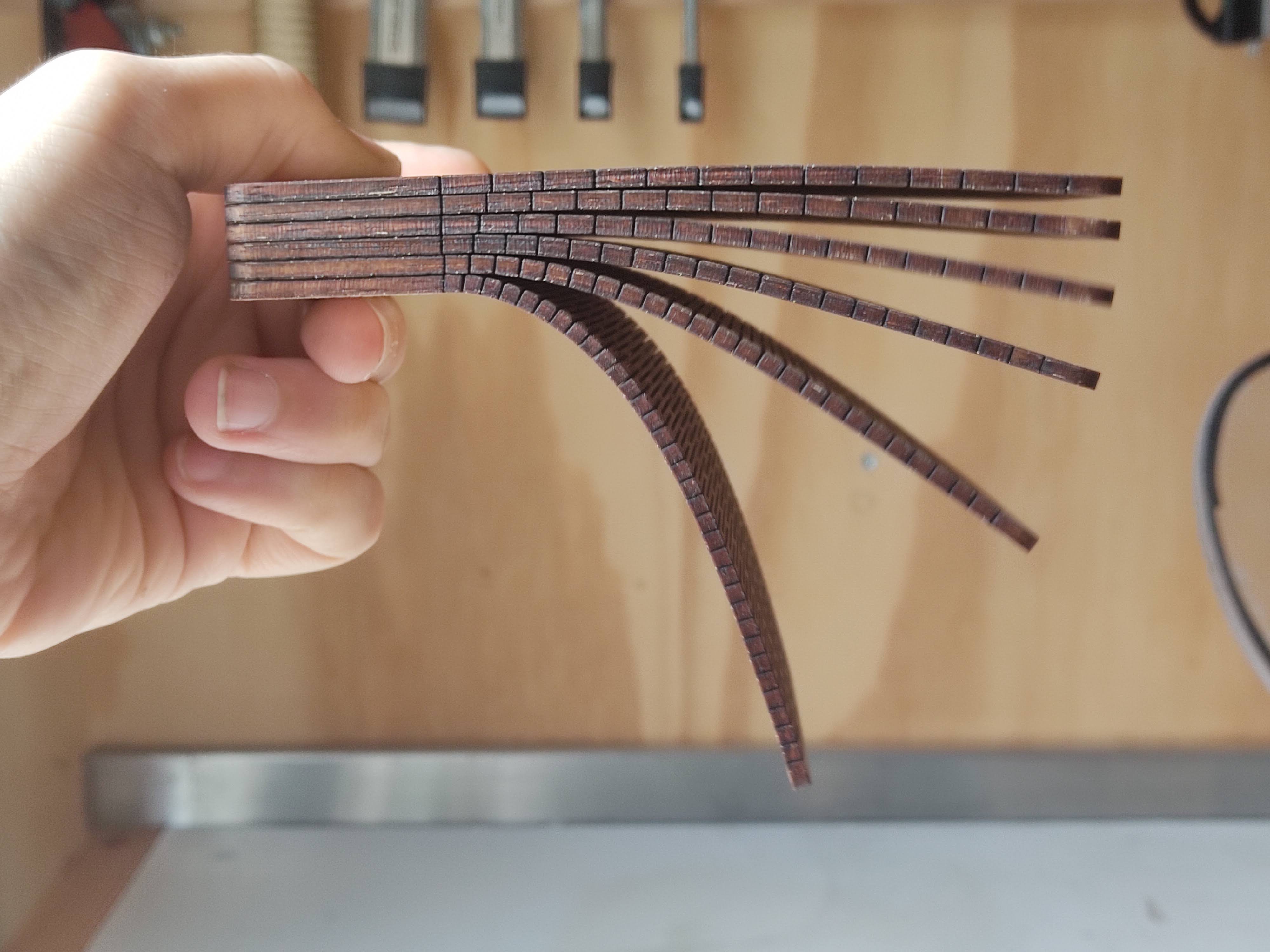
I had never curved plywood before. I know it can be done using moisture and heat and applying pressure, but that sounded like a lot of work and hard to do consistently right. So instead I cut a dense pattern of alternating slots into the plywood using the laser cutter. This is a trick that's often used to create bends in plywood. It degrades the strength of the plywood, but it should be fine for this piece.
To figure out how close the slots needed to be to get the curve radius I wanted, I cut a few test pieces. Turns out they needed to be pretty close together. It felt weird to hold wood that's so flexible. I know it mechanically makes sense, but it still made me giggle like a schoolgirl.
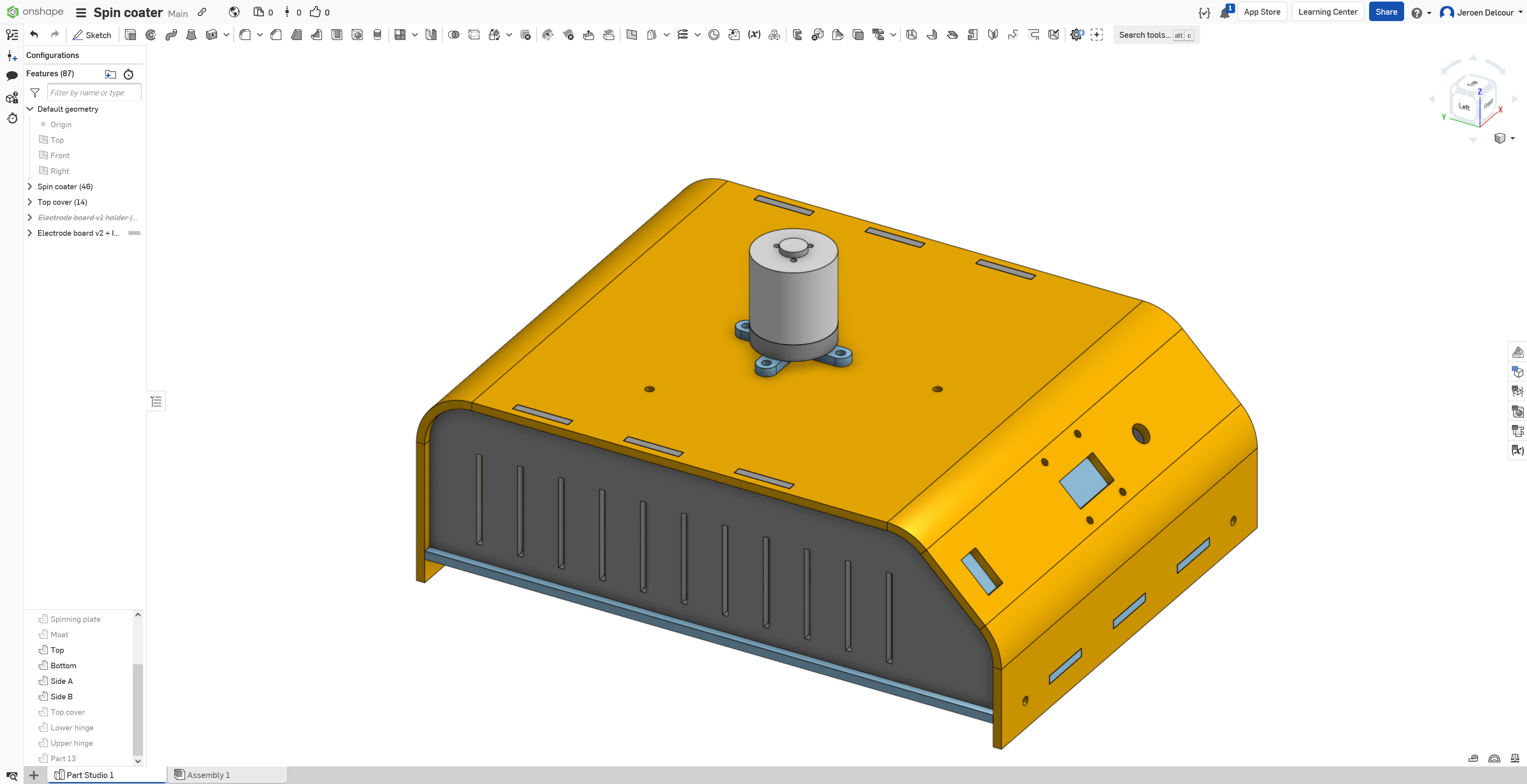
Here's the OnShape CAD document.
![]()
![]()
![]()
DIY Spin Coater
A spin coater is used to spread a thin layer of liquid on a flat surface to a very precise thickness, like photoresist on a PCB.
 Jeroen Delcour