 Nik Reitmann
-
1Get all parts
Print
Case printed in two parts, the rest can be printed in one piece. All printed with a Bambu X1C, a 0.6mm nozzle, in PETG with a layer height of 0.18mm.
The printing time for all parts was approx. 20 hours.
IO Panels are customizable (blank panels are foundable in files in this project).
The case is also available as [full] and as [splitted] in the files.Parts
Mostly AliExpress, see "components" in this Project.
-
2Post processing
Glued with epoxy resin and sanded with 320 grit sandpaper. Then primed several times, sanded wet with 600 grit sandpaper and painted with two coats.
-
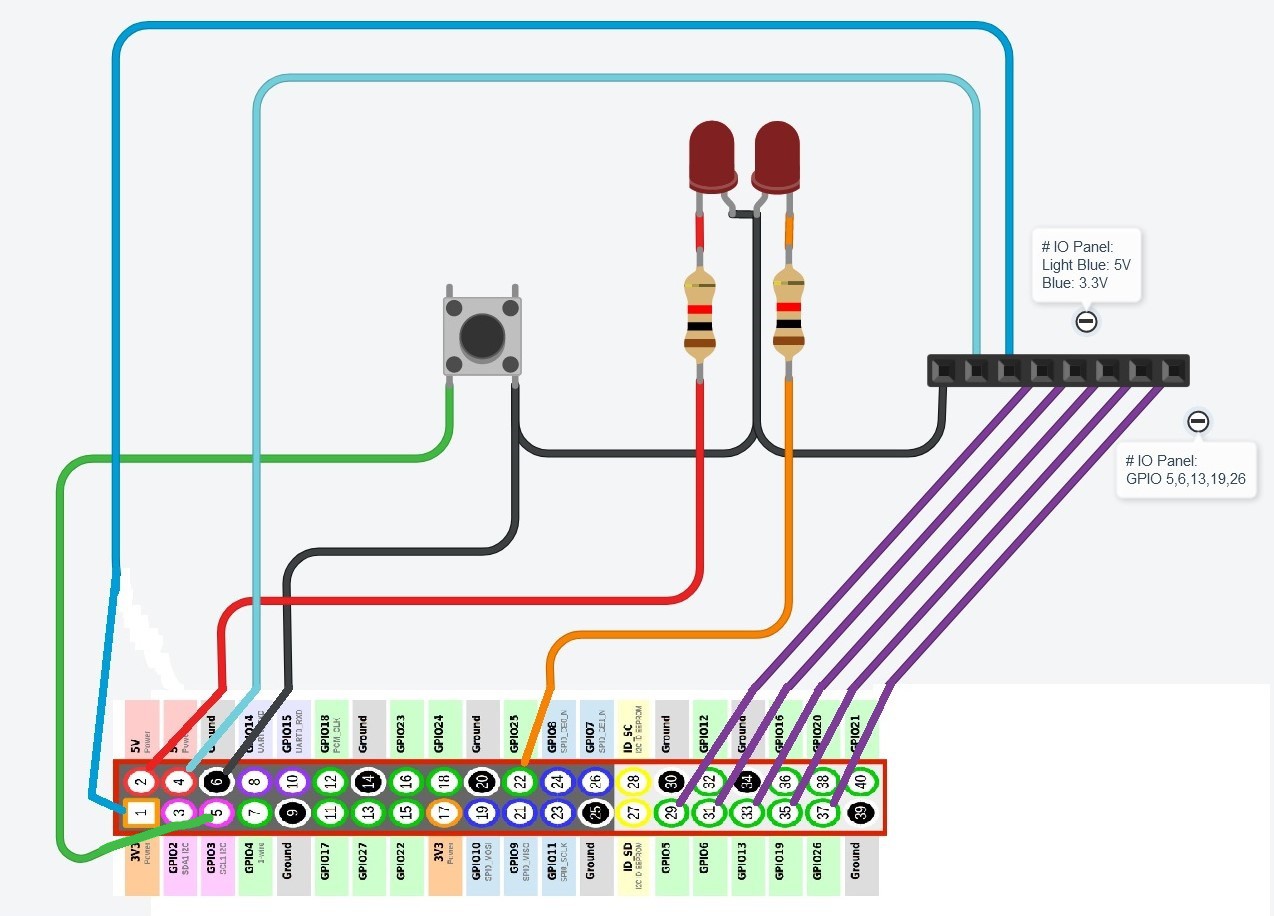
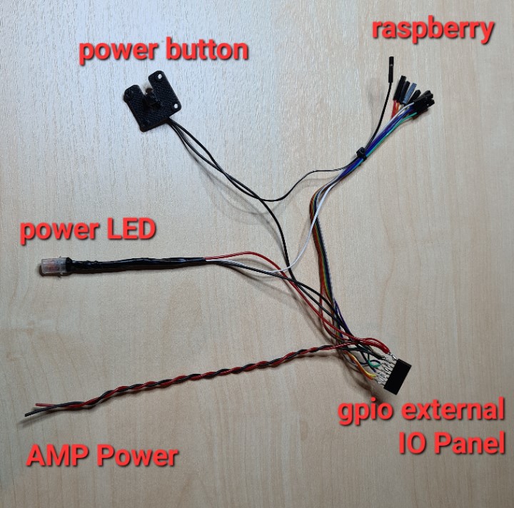
3Raspberry cables
![]()
raspberry circuit diagram ![]()
raspberry wiring harness -
4Peripherals cables
You can use the pins that you want on your microcontroller, in the peripherals_firmware you have to define your choosen pins. In the code the section with the PIN definitions is marked with "START_PIN_DEFINITIONS".

peripherals circuit diagram ![]()
peripheral wiring harness -
5Peripherals Firmware
Simply flash the "cyberdeck_peripherals.ino" code from the files to your HID enabled arduino.
If you want to change the direction of the knob you can swap the PINs in the code or physically swap the PINs on the Arduino
While the Arduino is still connected to the PC, you can use the serial terminal in the Arduino IDE to test whether everything is working. The terminal should output the following:
left mousebutton press
left mousebutton release
right mousebutton press
right mousebutton release
knoob rotate right
knoob rotate left
knoob pressed
-
6Assembly
The assembly is pretty self-explanatory. Provided both cable harnesses are soldered, the following sequence is recommended:
(all 3d printed parts are written in bold in the following text)
- remove all outer keys of the keyboard, insert them into the case and position them upwards to the stop
- keyboard_cover > case (4x M2 x 20mm)
- Reinsert the keyboard keys
- display > display_outer_frame
- display_and_sbc_mount > display_outer_frame (8x M2 x 16mm)
- screw display with display_and_sbc_mount together (8x M2.5 x 6mm)
- connect usb and hdmi to the display
- power_led -> display_outer_frame
- insert display_outer_frame in case and screw together (4x M2 x 16mm)
- insert rotary encoder and screw on with rotary_knoob_mount (2x M2 x 12mm)
- rotary_knoob > rotary encoder
- both mousebuttons > case
- trackball breakout board > case
- trackball_and_mousebutton_mount > case (7x M2.5 x 6.5mm)
- arduino > case (with a cable tie on the holder between display and keyboard)
- powerbutton > case
- powerbutton_mount > case (4x 2.5 x 6.5mm)
- speaker_grill > case
- speakers > case
- 3x speaker_mount > speakers (6x M2.5 x 6.5mm)
- cooler > rasperry
- raspberry > display_and_sbc_mount (2x screws and 4x spacers included with cooler)
- connect the keyboard and the peripherals arduino to the raspberry via usb
- prepare and install your IO and back panel
- cover > case (8x M2 x 12mm)
-
7OS install
Install your facorite raspberry OS (nothing special that might not work with some linux distros)
-
8LEDs
Power LED does not have to be done (this is at 5V), for the ACT LED the following must be entered in /boot/config.txt:
old EEPROM (< 000138c0):
dtoverlay=act_led_gpio=25

or with actual EEPROM Version (> 000138c0):
dtoverlay=act-led,gpio=25
-
9Fan
Use the fan function from raspi-config tool, you only have to set the right PIN and the temperature treshold.
-
10Display install
Better use actual instructions from:
TechNIK's Cyberdeck
A 3D printed compact and customizable linux terminal


Discussions
Become a Hackaday.io Member
Create an account to leave a comment. Already have an account? Log In.