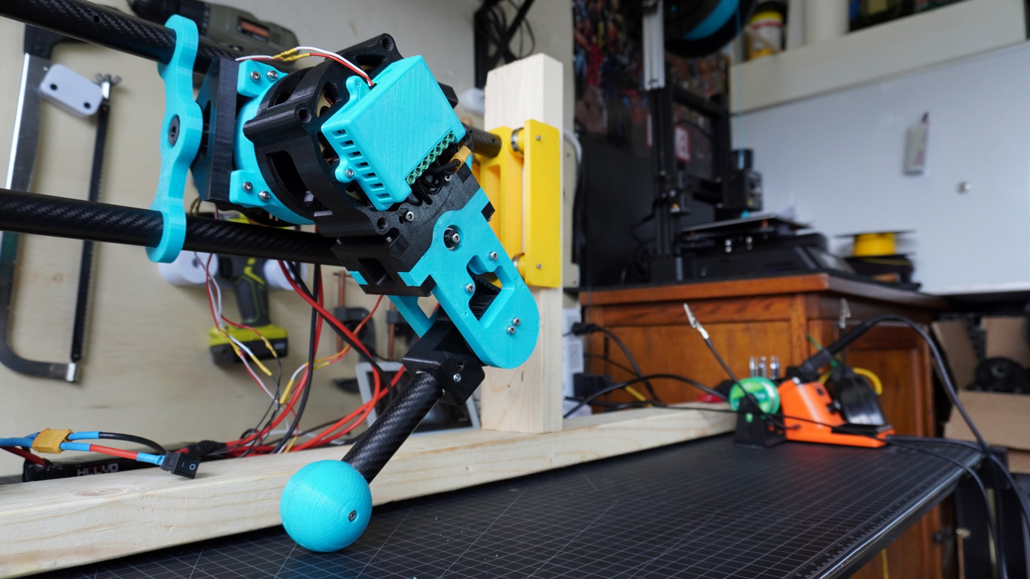
I’ve decided to redesign the leg before designing the full robot in order to address some issues that arose when testing out the V1 leg.
Physical Design Changes
- Got rid of using limit switches for homing.
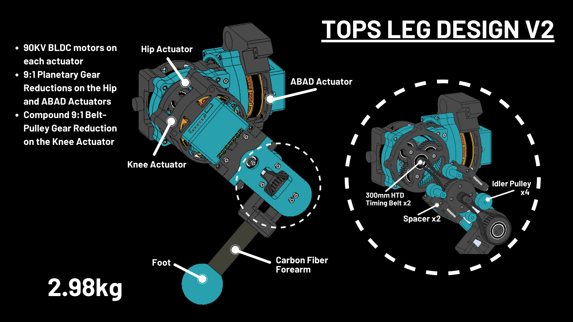
- Reduced total screw count and made it so that most of the leg can be assembled with just M4 x 40mm rather than assorted screw lengths.
- Took off about 1lb from the original design (V1: 3.42kg, V2: 2.98kg, 0.44kg or 0.97lb difference). Considering a full robot, I’ve now made it 4lb lighter which is quite significant. I’m estimating the total weight of the robot to be about 13-15kg. For reference, Spot from Boston Dynamics weighs 31.7kg.
- Made the leg design much lower profile by reducing how much the it sticks out.
- Reduced the complexity/print time of each actuator design. The BLDC motors are now visible which allows me to feel the motors when they get hot. It also just looks a lot cooler! The knee actuator had the most change. The knee actuator in V1 used 9:1 planetary gear set in addition to a 1:1 gear reduction for the belt pulley system to actuate the lower leg. Now, in V2, the knee actuator has no planetary gear set and a 9:1 reduction for the belt pulley system. This change was the biggest weight and size reduction.


Motor Control Changes
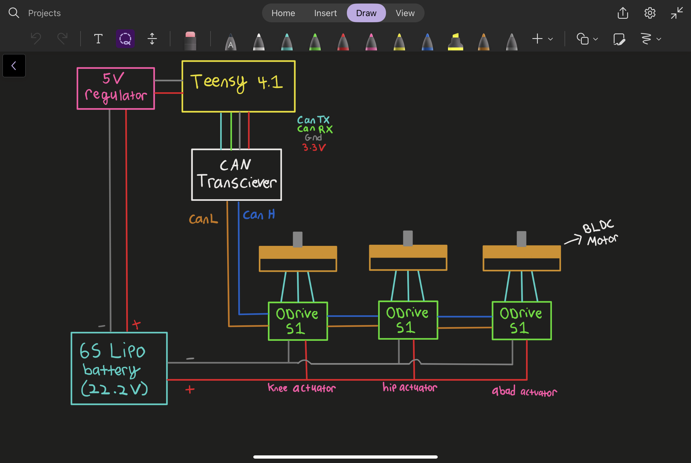
- Switched from UART to CAN BUS since the microcontroller that I’m using (Teensy 4.1) only has 8 out of the 12 serial ports that I would need to control 12 motors with UART on a full robot. With CAN BUS, in theory, I would only need 1 serial port to control 12 motors although it would be best to use 2 (6 per port).
- With CAN bus all motors are interconnected through two wires (CAN H, and CAN L) which significantly reduces wiring. For reference, with UART, each motor was connected to four wires for serial communication rather than two.
- The only limitation of using CAN bus is that the ODrive motor controllers that I’m using don’t yet have an official Arduino library for CAN bus so I’m not able to read the absolute position from the onboard encoders. This means that homing the actuators requires me to move the leg manually to a common position which I've integrated physical limits into the design.

Gait
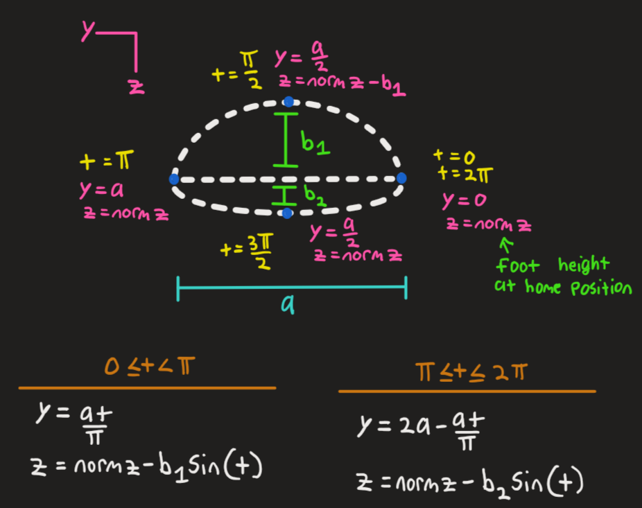
- In V1 I created a stepping sequence called sine step which moves the leg forward by following the path of a sine wave and then moves the leg back to the original position by following the path of a straight line. This time, the leg moves back to the original position by following the path of another sine wave (of small amplitude) rather than the path of a straight line. This is the same gait trajectory used by the Stanford Doggo and I’m hoping that this further smooths out the gait.

Jump Testing
- Shaving off so much weight got me thinking about making the leg jump.
- I’ve got the leg to jump a little less than 3.5”. With four legs the robot should definitely be able to jump.
- One issue I ran into while doing jump tests was belt tensioning of the knee actuator. The knee actuator carries the most load, so its belts have to be extremely tensioned to so that they don't slip during a high-impact landing. Although I haven’t tested this, reducing the position gains, which increases actuator compliance, should increase impulse and help reduce impact upon landing.
Weight Testing
- I've got the leg to lift 10 lbs meaning that the robot should be able to lift 40lb, which shouldn’t be confused with how much weight it will be able to walk with (most likely less than 40lb). I did further testing with a scale and the leg should be able to lift up to about 13lb.
 Aaed Musa
Discussions
Become a Hackaday.io Member
Create an account to leave a comment. Already have an account? Log In.