 Arduino Enigma
-
Programmable Seven Segment LED Tester is complete
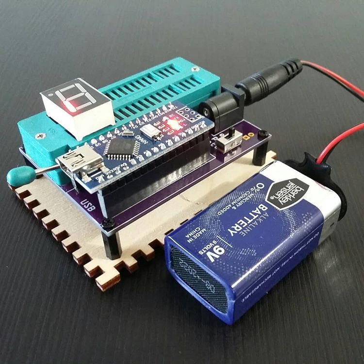
08/07/2023 at 05:29 • 0 commentsHere is the finished Seven Segment Tester. All of the available Arduino Nano pins, except for analog input pins A6,A7 and Serial Port pins D0 and D1 are connected. This leaves us with 18 pins to bring to the 3M Zero Insertion Force (ZIF) socket. Any display up to 9 pin DIP can be tested.
This video shows the test patterns for a 16-segment LED display and a three-digit seven-segment display.
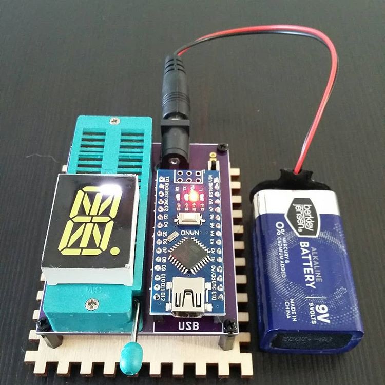
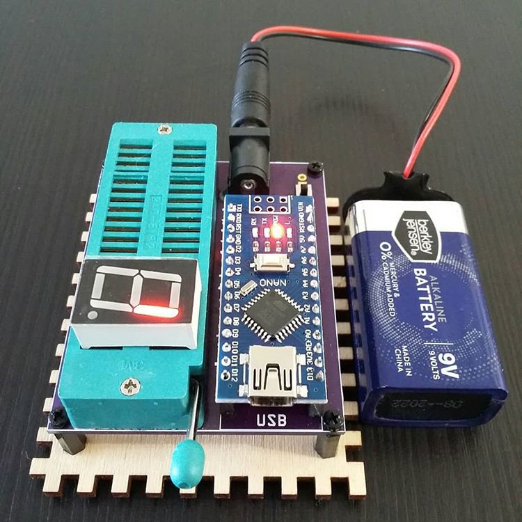
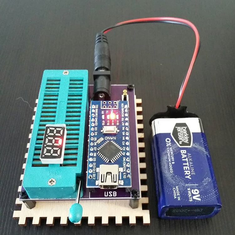
Here are some pictures of the device testing a 16 segment display, a 7 segment display and a 3 digit 7 segment display. The common cathode and common anode versions are programmed as test patterns.
Once the Arduino is programmed, the device can work standalone using a 9v battery.![]()
![]()
![]()
![]()
![]()
The base is a reused enigme simulator box lid.
![]()
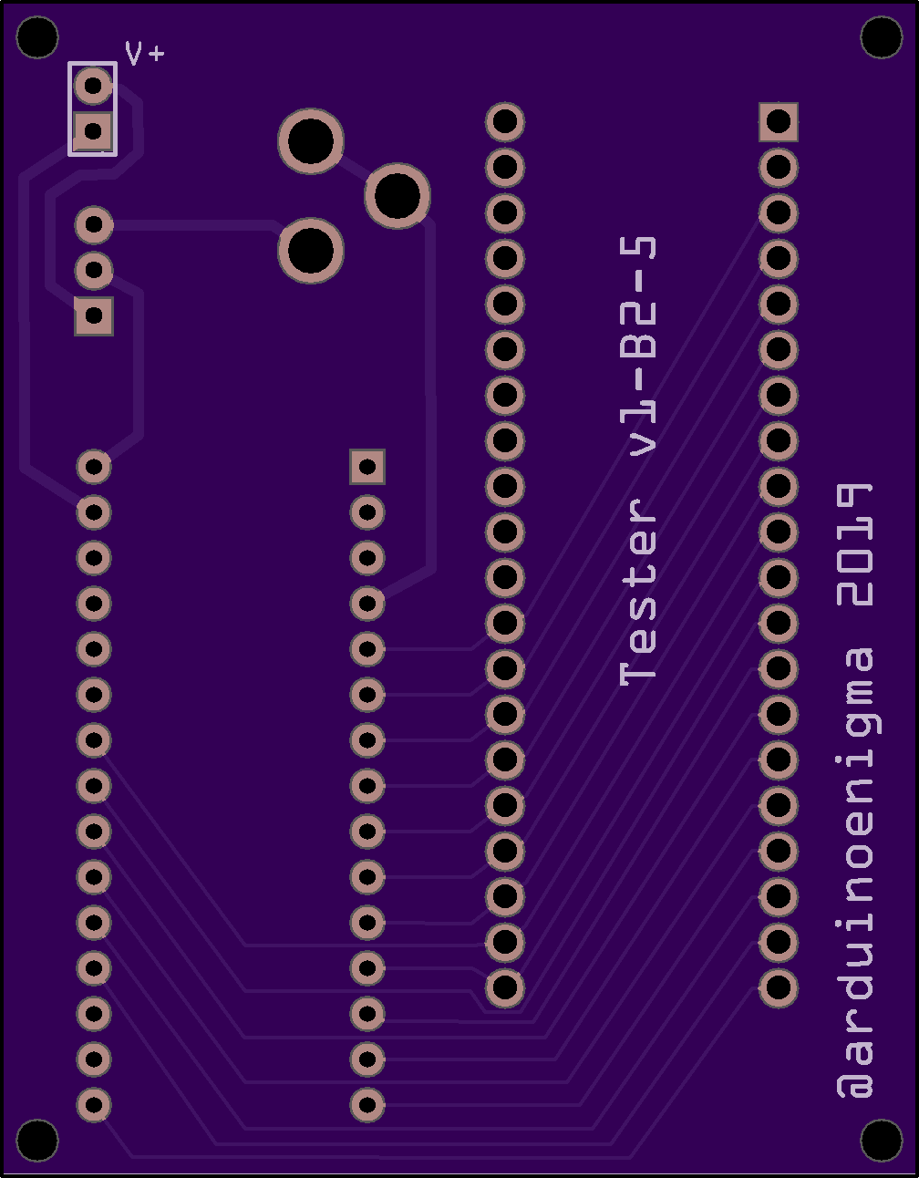
The OSHPark render of the bottom of the board.
![]()
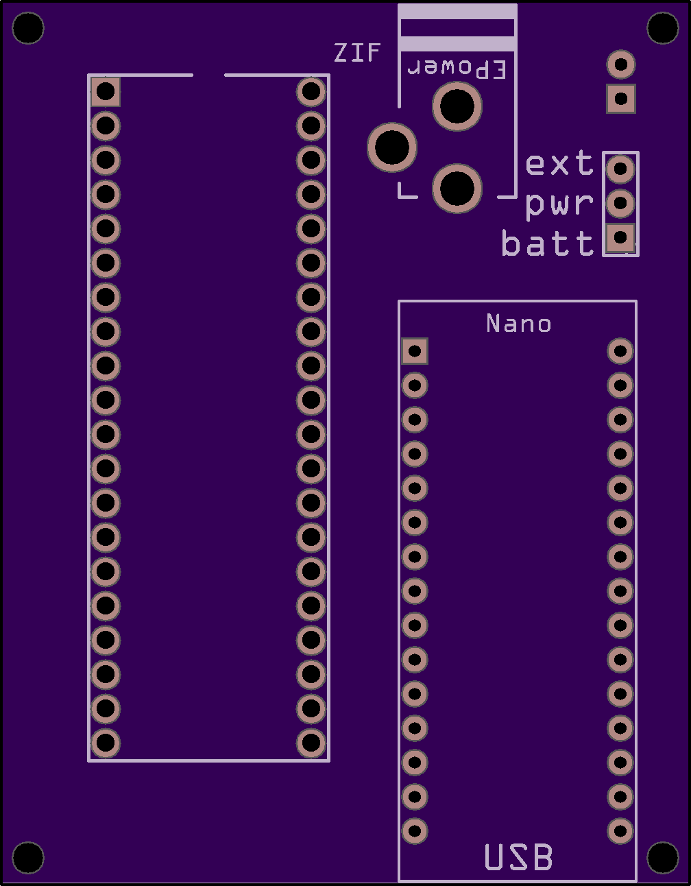
A render of the top of the board.![]()
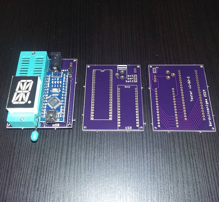
The boards as they came from Oshpark.com
![]()
This design may also be used to test IC, it can supply power and ground to the device under test, put values on some pins and verify that the output from the chip is correct.
-
Idea for a Seven Segment LED tester
08/07/2023 at 05:14 • 0 commentsThe seven segment displays required for previous projects had, on rare occasions, defective segments. In order to test them all, some contraptions were devised.
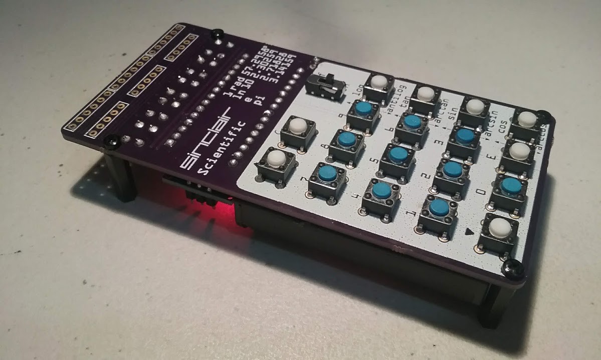
Here is a calculator without the displays soldered. Testing the display involved inserting the display in the PCB and running a special program that cycles through all the digits.
https://arduinoenigma.blogspot.com/2018/03/new-product-post-sinclair-scientific.html
![]()
This is another rig to test a single seven segment display for the Art Installation Project. This one simply illuminates all the digits simultaneously. The Arduino UNO is simply providing 5V and all the digits are hardwired with jumper wires.
![]()
https://arduinoenigma.blogspot.com/2019/04/the-seven-segment-art-installation-has.html
Faced with the prospect of testing the 16 segment displays for the Mega Enigma, building another single purpose jig was not an attractive option.
https://arduinoenigma.blogspot.com/2019/05/enigma-simulator-pcb-almost-ready-for.html
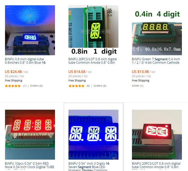
Most of the Led listings on AliExpress shows the displays being tested on some sort of ZIF socket. We will set to build something that works like that.![]()
The following socket was found:
![]()
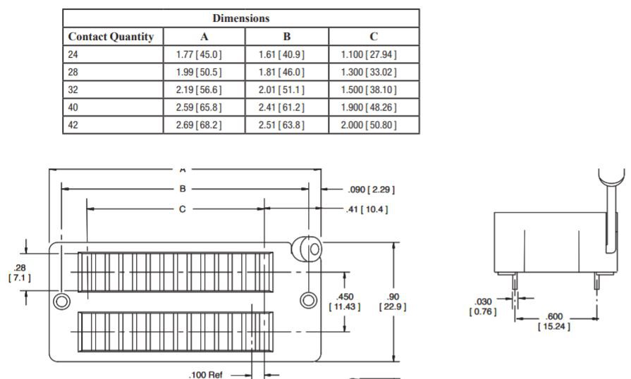
Here is the datasheet for the socket, we'll design a PCB based on these dimensions and adjust it later if needed.
![]()
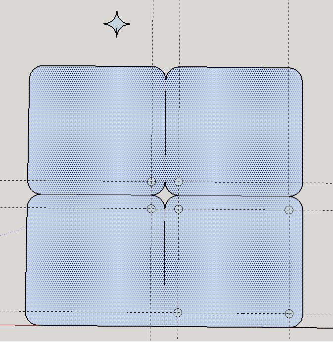
And here is a preliminary PCB design. It is a very simple design where the bottom 9 pins on the socket are connected to an Arduino Nano.
![]()
![]()
![]()
Here is a preliminary design for a laser cut base. This design shares an edge between two pieces to minimize laser cutting time and therefore cost.
![]()
Once the socket arrives, the design for the tester and its base will be finalized. This will be a low cost tester, notice only the bottom 9 pins are wired, and that is good enough for the 16 segment displays. A later design might use the Mega Pro Mini and wire all the segments in the socket.
Programmable Seven & Sixteen Segment LED Tester
An Arduino Nano and a ZIF socket makes for a minimalist stand alone programmable LED and display tester. No extra buttons. No resistors.


