-
Module well wiring
12/19/2023 at 01:38 • 0 commentsI was not keen on to put here something small, so this update took an embarassingly long time to come up with, especially considering what came to fruition.
First of all - holy moles, the deck actually won the contest. I was hoping to get into some kind of notable category (painting this whole thing was tedious after all), sure, but this blew me away. Thanks Hackaday Team!
What I was working on was a way to route RPi GPIOs into primary module well, so it could function, as, well, a module well. So I could connect something there without disassembling the whole thing.
There was no way i could just grab a 2.54 20x2 and botch some 24AWG wires on it and run the whole bundle somewhere in the backplate until it surfaced in the module hatch. There are slots for that, yes, but it needs to be tidy to some extent and also there was no way to fit standard 2.54 headers onto a Pi - there was no headroom.
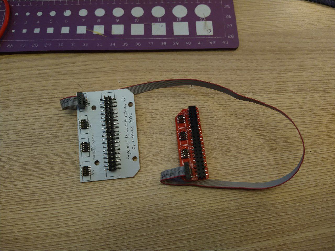
So i've decided to make two PCBs - one to convert GPIO header into something smaller (say, a flat cable) and then run that and convert it back into 2.54 format, more suitable for prototyping things.
First PCB order was botched - i did not check how they were connecting to eachother, so they were forming a mirrored GPIO layout. So i rerouted everything and sent everything back - that's almost two months before these arrived:
![]()
![]()
![]()
Looked tidy enough, but there was a problem. This bundle was lifting the back case cover and also it was permanent - you simply could not remove these cables without cutting those 1.27 IDC connectors. The permanency was the least of concerns, but that lifting business, that was a nono.
![]()
And it turned out - the top board was not fitting the primary cover (the one with a charging indication). And i was not in the mood to reprint and repaint it again. No, hell no. Next time, when chosing the CAD for PCB design - check thoroughly if it able to export into 3d cads with a proper format - EasyEDA can export either a good quality 3d model for referencing in case design - but the model will be wildly out of proportions, or it can export DXF - but that is 2D only and good luck deleting all the unnecessary shapes on that.
So, back to PCB design, another order, wait for another month of wait, all while redesigning the little left cover to fit the header. Another fitting job without actual reference hardware, another painting work, no red this time.
And finally it arrived - the new board is white, assembled and ready to be installed:
![]()
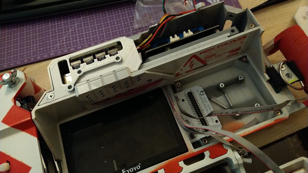
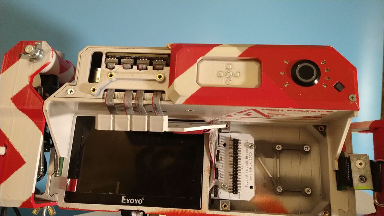
This time i've designed a little shroud that goes in front and supposed to contain all the flex cables in it.. But i miscalculated the thickness and could not make it any more thick either - it would not allow keyboard to close snuggly. So i've had to run everything semi-externally. Adds to the aesthetics i guess.
Oh and i've also had to cut the little cover to fit all the flex cables when they bend - i'm yet to update CAD files for that, so it may not be taken into account at the moment of STL uploading.
![]()
![]()
![]()
![]()
![]()
I was in such hurry to assemble everything, i skipped the part where i usually test everything with continuity tester. And so, naturally, the monster of short-circuits, the beast he is, just waits to bite your bum in the most unexpected and cruel way - i missed the short circuit on one of GPIO pairs and it resulted in, what is my best guess, a RPi PMIC going into thermal shutdown and not wanting to boot back again for some time. Almost had a heart attack at that point - some projects just hate me more than i hate them, i guess.
Fortunately, after cutting a connector and crimping another one, the short was gone.
Btw the layout on the breakout looks something like this - you look at the board to the left, and imagine your RPi board looks like the one to the right. Sort ot unconventional, but it works imo.
![]()
So RPi is back alive, and i needed some way to test if it truly works. Do something digital, but something on the cheap and quick. LoRa is out of reach for me (yet), so it needs to be simpler.
What do you do when you get the ability to connect digital stuff to your board?
That's right - you connect a strip of neopixels and vibe away.
![]()
![]()
And instead of a postscript - here is how charging indication board has evolved (from top to bottom). I've worked on it too while the whole business above allowed. A motivational reminder that when you persist - things, after all, move forward.
![]()
-
Indication v2
09/20/2023 at 09:56 • 0 commentsNow that boards have arrived, time to soup up the indication panel with something a bit less messy.
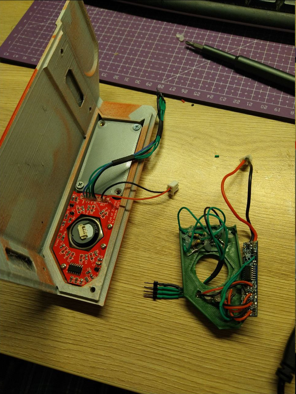
The new board is to the left.
Board archive for instant JLCPCB quote will be added to file archive. You will also need new spacer panel which receives PCB bolts and is tied to the case with large power switch nut.
The only problem with it is that i have used PH2.0 connectors to interface the board with everything, and even they have high enough profile to push against battery caddy and prevent top cover from being flush when assembled.
So for now i will not use PH2.0 connectors and just solder power and interface wires directly and apply some sauce to add strain relief - after all you absolutely do not want your battery terminals to break off easily and fly around within enclosure to cause high octane havoc. Maybe i will release another board revision that has connectors moved to the top part so they won't press against battery caddy since this is more safe.
The board also comes with separate indication trigger pin alongside of power to user leds - this will allow to trigger charge level indication with whatever signals you wish, basically (as long as it is within 3-5V range). I will use VIN pin on UPS hat so that when charger is connected - indication panel will display current charging level. Remember though that this battery level indicator only relies on direct battery voltage measurement - hardly a precise way of telling if tanks are full.
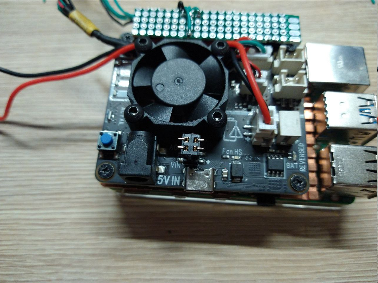
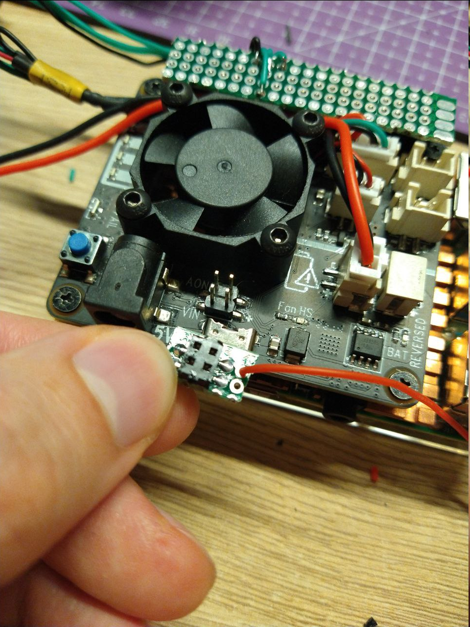
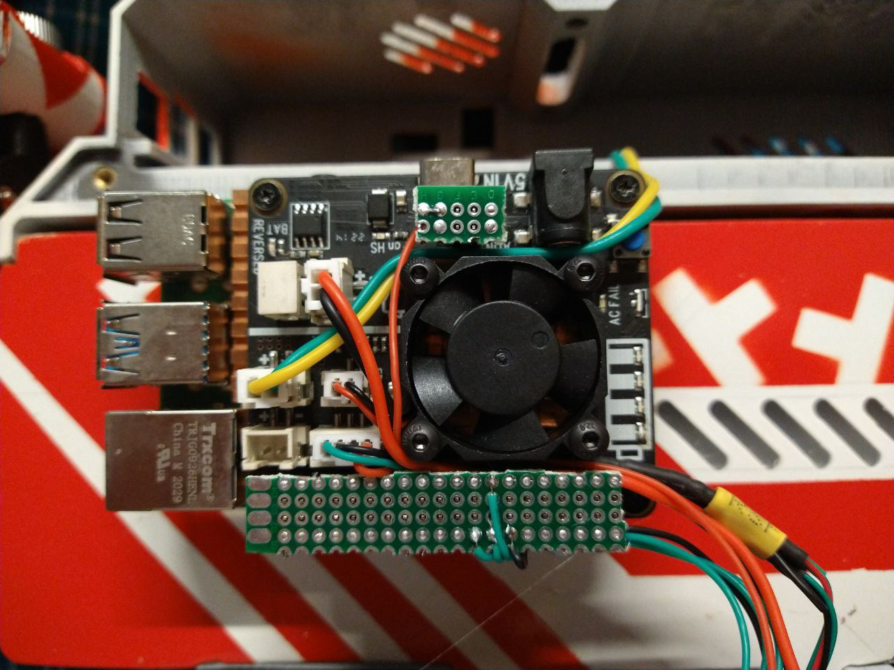
Grab another low profile 2.54 header - there is not much space around motherboard to fit full size ones. Solder it to a piece of smallest perfboard you could find, bodge a jumper wire to "VIN +" near USB power connector on UPS hat and route this wire to CHRG pin on USER connector on the indication board. Since this pin active high, you can probably also add two diodes and connect Pi GPIO in parallel, so that you also can control indication from the Pi, but i'm not going to do that for now.One nice thing about this little connector board is that it clamps display power connector under it so it won't fly around when you are working with the board.
The amount of parasitic additions asks for another HAT to be designed.There ain't much new to demonstrate though, i've shown how indication panel works before but here is a more marketing friendly action which shows how new leds flash and how board reacts to charger connected.
On less important note, i've found these cool angle USB connectors connectors to tidy up the left side of things
And free advice for the most patient readers: please have enough sleep especially when actively working on a project. Assembling the board was not really hard, however when parts arrived, it's either me or the seller who swapped N-mosfet reel with P-mosfet reel, which took me 2 hours at 3am to figure out after the fact that i've soldered both onto the board (basically means that both of them are open when power is applied, which was not the intended effect).
But the most clear demonstration of what sleep deprivation can do to your ability to build blinky things is the realization that i've soldered Q2 gate transistors... 90 degrees rotated from how they are supposed to be fitted. Which made Q2 always open even when i figured out which was the correct reel the seller sent me and it drove me nuts.
And before a keen eye says "your PCB design allows to do that" - that PCB was also designed mostly at 2-4am in the morning, so, yeah, sure.
But hey - the relief of fixing your own mistakes is worth it, right?![]()
-
Boarding up
08/27/2023 at 23:58 • 0 commentsTo tidy up the indication panel, it was decided to move li-ion gauge schematic and user LEDs onto a single PCB. A little reverse engineering was required - these gauges work too good to look for more schematics on the net.
So here is my interpretation of it, not really big of a deal, just an ol dumb quad-opamp with a TL341 as a reference rail and pmosfet which turns whole schematic on when button ties it's gate to the ground. No idea what red path does - i have several of these modules and some feature that diode connected to input voltage, some don't, my own pcb won't feature it and pmosfet source will be connected directly to battery positive terminal.
![]()
After some messing around in easyeda:
![]()
Just connect your 1S Li-Ion to VCC/GND terminal and once you press the button, charge gauge should show approximate fuel left in your tanks. Calibrating it is probably whole another story, but i hope schematic is clear enough where should you look for that. Oh and you don't connect R21NC between Q1 gate and INDICATOR_EXTCTL - this one is for a case when there is a need to have external charge gauge trigger control, but it will have active low polarity. It's just i have no idea how to set up "do not populate" parts properly.
USER header is where Pi GPIO signals go to light up leds for any purpose. INDICATOR_EXTCTL supposed to work as a digital pushbutton - provided you install Q2 and appropriate parts around it. So and then you can route this signal to either GPIO, or, which i will probably go for - route it to UPS HAT external power input, so once i connect it to charger - battery gauge will light up to let me now when i should disconnect it.
Now slap together a PCB and push it into production. And while i'm at it - spin some breakout PCBs to route RPi GPIO into primary module well.
PCB/schematic projects will be published once they arrive and i verify they work as intended.
With any luck.Edit: i forgot to transfer 100n capacitor from original schematic. Oh well. Looks like usual bypass cap, so slapping it on somewhere along voltage supply rails should work, right..?
-
Cyberdeck Cafe entry
08/21/2023 at 17:28 • 0 commentsPrecious folks have put the project entry at Cyberdeck Cafe, hell yeah!
-
SDR carrier
08/14/2023 at 17:56 • 0 commentsGet it? Because radio signals have carrier frequency?
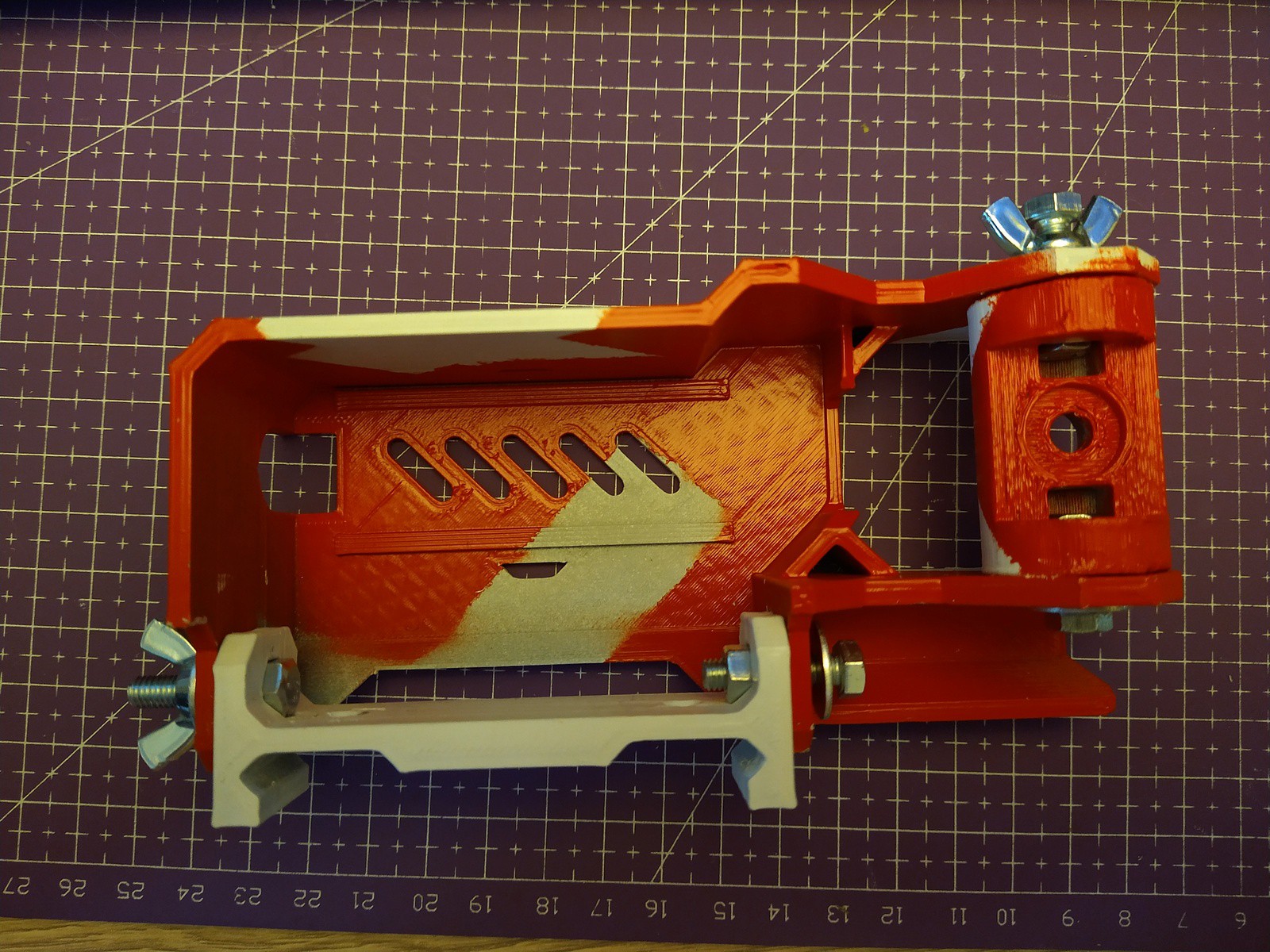
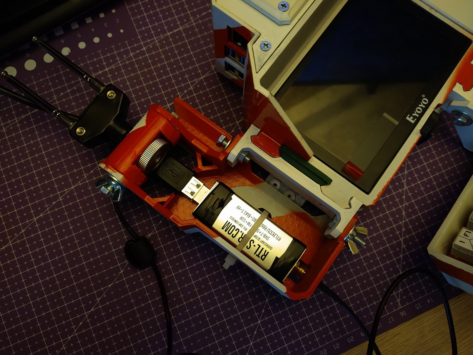
So, i've added another rail attachment which can hold a generic SDR dongle and generic "rabbit ears" antenna on a swivel mount (how handy it has 1/4" threaded mount so that is what is going to be needed to build here)You're going to need
- 3x M5 x 20mm (total length) bolts,
- 1x M5 x 14mm (thread length) bolt,
- 3x M5 nuts, 2x M5 wing nuts
- 4x M5 washers
- 1/4" tripod male-female adapter
- Generic "RTL-SDR Blog" dongle that comes with antenna
- Printed parts
![]()
Add some paint work
![]()
Assemble
![]()
Put SDR and antenna mount inside, vigorously apply some cable ties (or velcro), mount the thing on the thing![]()
Please do not do this - i took first USB extender i had and i probably should have went to aliexpress for some smart 90deg usb plugs or something, because this is barely acceptable:
![]()
And boom, you are now prepared to commence some r e c e p t i o n. Fire up gnuradio-based-sdr-ui of choice (i've found Gqrx SDR ui works well, but the reception itself is rather subpar because reasons) and receive to your heart's content.
![]()
Or just, flex your aerial and be done with it
![]()
-
Indication panel wiring
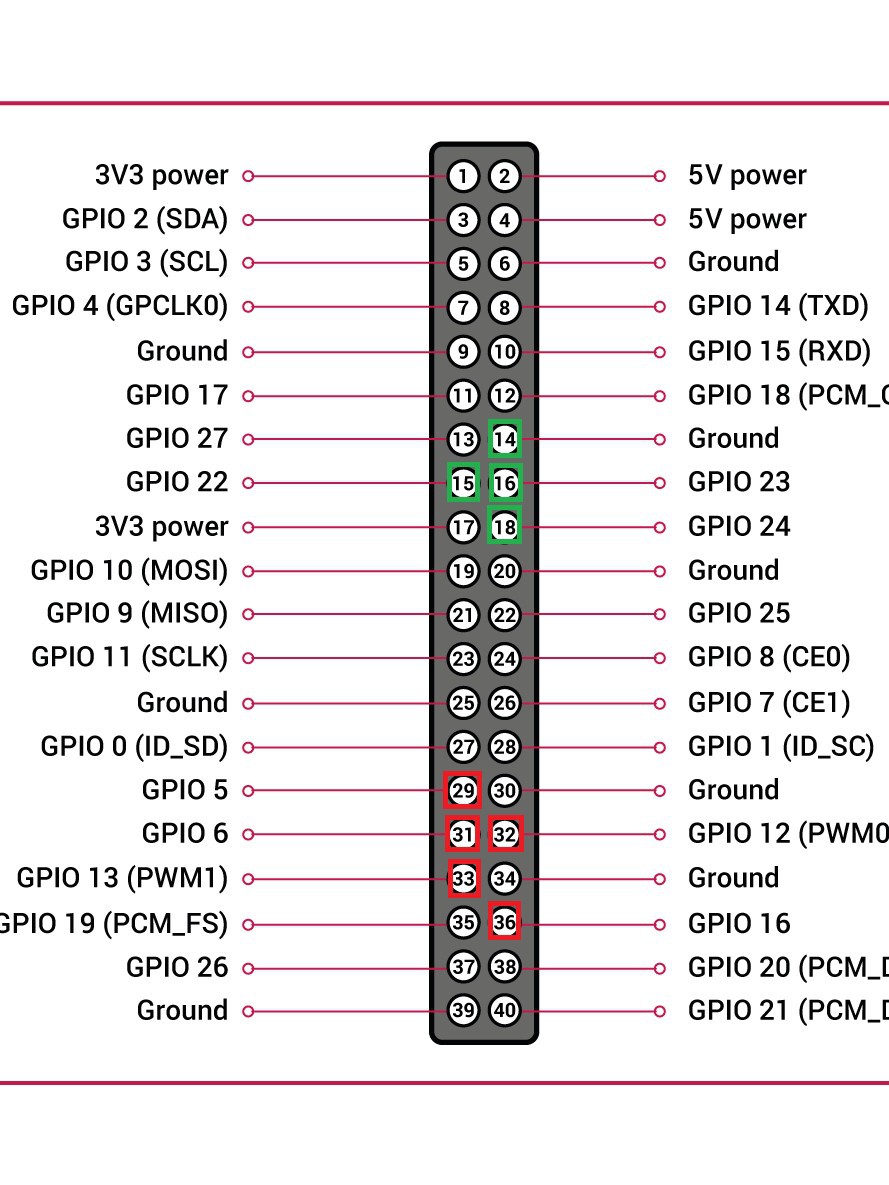
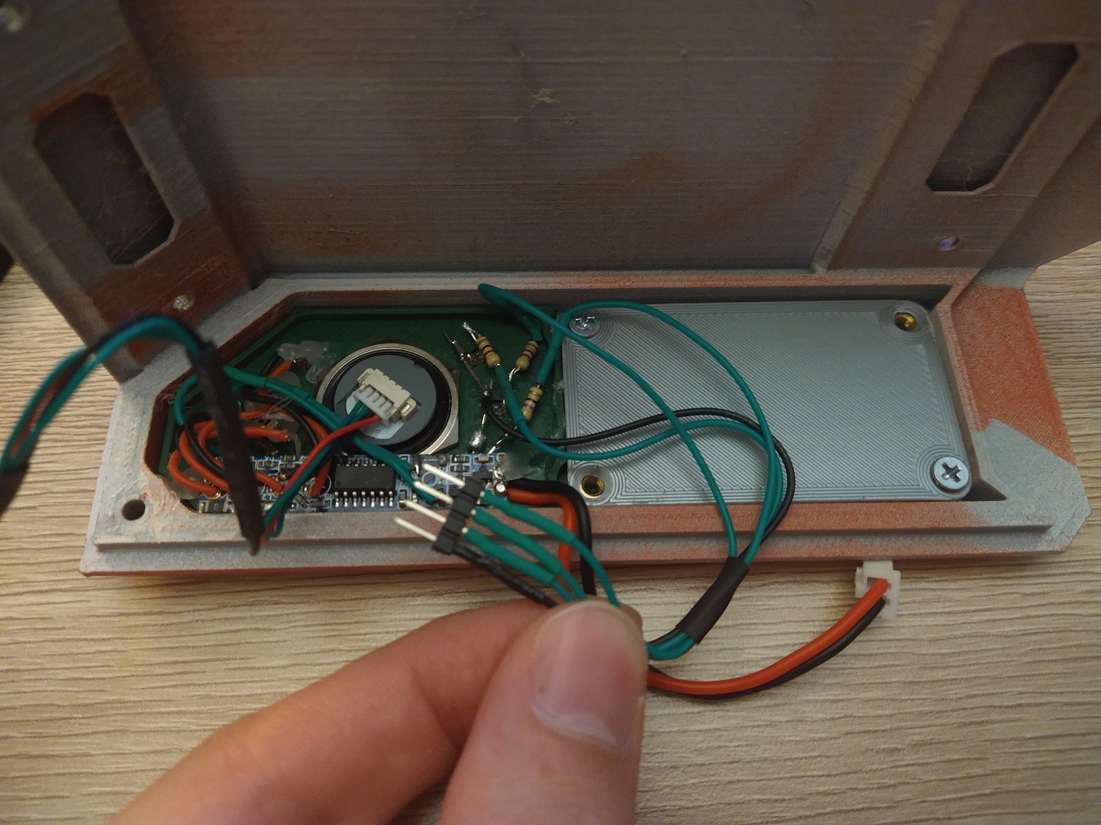
08/09/2023 at 00:57 • 0 commentsSo today i've got my low profile 2.54 headers for the Pi from Aliexpress and that means that it is time to connect those three LEDs left on primary cap alongside of battery level indicator.
Since UPS HAT already occupies some GPIO for it's purposes (these are marked red), i've chosen another set of GPIOs to hook up cap leds (marked in green)
![]()
Some assembly pics:
![]()
![]()
![]()
![]()
And if everything is done correctly, after booting basic GPIO toggling python script, you may be greeted by this (new leds are to the left of the power switch):
Some use cases are probably to indicate things like WLAN status, battery low, messenger unread blinking... You name it.
-
Initial commit
08/09/2023 at 00:49 • 0 commentsSo, i've done component list, provided files and assembly instructions, so it probably should be that minimum to call it a "project".
There are probably few more steps pending - i'm about to write about notification panel wiring and maybe there will be a SDR attachment soon.
 mkdxdx





 The only problem with it is that i have used PH2.0 connectors to interface the board with everything, and even they have high enough profile to push against battery caddy and prevent top cover from being flush when assembled.
 One nice thing about this little connector board is that it clamps display power connector under it so it won't fly around when you are working with the board.
 There ain't much new to demonstrate though, i've shown how indication panel works before but here is a more marketing friendly action which shows how new leds flash and how board reacts to charger connected.
 And free advice for the most patient readers: please have enough sleep especially when actively working on a project. Assembling the board was not really hard, however when parts arrived, it's either me or the seller who swapped N-mosfet reel with P-mosfet reel, which took me 2 hours at 3am to figure out after the fact that i've soldered both onto the board (basically means that both of them are open when power is applied, which was not the intended effect).


