Monstrofil
-
Sidequest: overclocking imx477 camera
05/31/2024 at 17:47 • 1 commentI'm writing this primarily for my future self, who may one day decide to return to the IMX477 driver implementation to add features like HDR support, 4 MIPI lanes, or 4K 60fps mode.
The issue is that the RPI implementation of the driver is locked at a maximum of 10 fps in 4056x3040 mode. While this may be suitable for the RPI with its slow processors and ISP, which can only handle 1080p images, it is insufficient for the RK3588.
https://github.com/raspberrypi/linux/blob/rpi-6.6.y/drivers/media/i2c/imx477.c#L945
---------- more ----------To start, I want to provide some basic knowledge about how IMX sensors work.
On the Raspberry Pi forum, there are several topics discussing cameras and MIPI-CSI, but one thread is particularly interesting. It explains how the LINK_FREQUENCY and PIXEL_RATE values in the driver code work, why the Raspberry Pi is limited to 10 fps, and what the HBLANK and VBLANK values are: Raspberry Pi Forum Post.
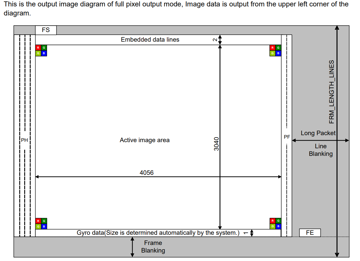
For better understanding, I included an illustration from the datasheet. As you can see, while the raw image is being transferred, it does not completely fill the space within the packets, leaving free space horizontally (HBLANK) and vertically (VBLANK).
If you examine the VBLANK and HBLANK values using
v4l-ctl, you will see that the horizontal blanking value is extremely high, occupying almost four times more space than the line width itself.root@orangepi5:~# v4l2-ctl -d /dev/v4l-subdev2 --list-ctrls Image Source Controls vertical_blanking 0x009e0901 (int) : min=252 max=8380960 step=1 default=252 value=252 horizontal_blanking 0x009e0902 (int) : min=19944 max=19944 step=1 default=19944 value=19944 flags=read-onlyThe first thing you should try is to lower the horizontal blanking value. In the driver, this is defined by the line_length_pix constant for each mode and the corresponding registers at addresses 0x0342 and 0x0343.
    {
        /* 12MPix 10fps mode */
        .width = 4056,
        .height = 3040,
        .line_length_pix = 0x5dc0,
....
        .reg_list = {
            .num_of_regs = ARRAY_SIZE(mode_4056x3040_regs),
            .regs = mode_4056x3040_regs,
        },
    },


/* 12 mpix 10fps */
static const struct imx477_reg mode_4056x3040_regs[] = {
    {0x0342, 0x5d},
    {0x0343, 0xc0},
You can lower that value by approximately 10% and achieve around 12 fps at the stock clock speeds (don't forget to adjust timeperframe_min and timeperframe_default). However, further reduction will result in a "broken" image.
![]()
Test capture of vertical coloured lines test pattern. My initial thought was that by changing the register values, I somehow broke the horizontal synchronization trigger (as vertically, the frames were still correct!). However, further investigation revealed that the reason was completely different.
To proceed, I need to provide more understanding of how IMX sensors work internally.
While the IMX477 datasheet available on the internet is somewhat limited, it still contains plenty of useful information, including the Clock System Diagram, which explains how the data flow is designed.
IMX477 clock system diagram On the left side, we can see INCK identified by the EXCK_FREQ. This is a base clock value used in all module subsystems. However, that value can be multiplied or divided by constants like IOP_PREPLLCK_DIV and IOP_PLL_MPY, resulting in multiple different clocks like ADCK, CPCK, IVTPXCK, and so on.
In the middle of the pipeline, there is a buffer called FIFO, which uses the IVTPXCK and IOPPXCK clocks for its operation. Considering that the RPI driver is initially limited by the slow MIPI lane on their processor, I started changing the IOPPXCK clock speed.
IOPPXCK can be calculated as INCK / IOP_PREPLLCK_DIV * IOP_PLL_MPY. While register names are not usually published, one of the developers on GitHub was kind enough to list all of the register names and their corresponding values.
REG_IOP_PREPLLCK_DIV=0x030D,  # The pre-PLL Clock Divider for IOPS ,
REG_IOP_MPY_MSB=0x030E,  # The pre-PLL Clock Divider for IOPS ,
REG_IOP_MPY_LSB=0x030F,  # The PLL multiplier for IOPS [7:0]  ,
I grab those values and wrote a simple tool to easily compare different register sets.
https://github.com/Monstrofil/sony-imx-controlsREG_EXCK_FREQ (00310 | 0x136) => 24 (0x18) REG_IOP_PREPLLCK_DIV (00781 | 0x30d) => 2 (0x2) REG_IOP_MPY_MSB (00782 | 0x30e) => 0 (0x0) REG_IOP_MPY_LSB (00783 | 0x30f) => 150 (0x96)
Surprisingly, if you take the register values and perform the calculation 24 / 2 * 150, you get 1800, which is also known as 450 x 4 and was mentioned in the post on the RPI forum. I'm still not sure what that magic constant 4 represents, but throughout the whole process, I had no trouble defining IMX477_DEFAULT_LINK_FREQ as INCK / IOP_PREPLLCK_DIV * IOP_PLL_MPY / 4 * 1000000.In my case, I changed REG_IOP_PREPLLCK_DIV to 3 and REG_IOP_MPY to 0x0140 (320), which gave me a LINK_FREQ of 24 / 3 * 320 / 4 * 1000000 = 640000000.
And it worked! After changing the LINK_FREQ, I was able to lower the HBLANK space and achieve around 25 fps. However, there was a weird ghosting effect on the right side of the frame.
![]()
Long story short, the issue was the balance between the IVTPXCK and IOPPXCK clocks. After I increased the IVTPXCK clock speed a little bit, the ghosting went away, and I was able to achieve a stable 30 fps.
It also turned out that while IVTPXCK is defined as EXCK / REG_IVT_PREPLLCK_DIV x REG_PLL_IVT_MPY / (REG_IOPPXCK_DIV x REG_IOPSYCK_DIV), which is 24 / 4 * 0x015e / (5 * 2) = 210 for the original driver, it also matches the PIXEL_RATE as PIXEL_RATE = IVTPXCK x 4 x 1000000. Again, the constant "4" appears, but this time it multiplies rather than divides the resulting value.
After some trials, I ended up with a 984M pixel rate mode specifically for my new 4K 30fps mode and modified IVT dividers.
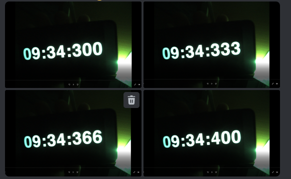
#define IMX477_PIXEL_RATE_984M        984000000

  REG_IVTPXCK_DIV           (00769 |    0x301) =>          5 (0x5)
  REG_IVTSYCK_DIV           (00771 |    0x303) =>          2 (0x2)
  REG_IVT_PREPLLCK_DIV      (00773 |    0x305) =>          4 (0x4)
  REG_PLL_IVT_MPY_MSB       (00774 |    0x306) =>          1 (0x1)
  REG_PLL_IVT_MPY_LSB       (00775 |    0x307) =>         94 (0x5e)
  REG_IOPPXCK_DIV
And that finally allowed me to get these images:
Capturing stopwatch at 4k 30 fps with imx477 camera While being relatively straightforward, this process actually demotivated me to the extent that I shelved this 360 camera project for almost a year.
-
Drivers
09/03/2023 at 21:55 • 0 commentsFirst thing that you need in order to work with mipi camera on software level is kernel driver. Linux uses v4l2 layer in order to provide API for userspace applications. RockChip extends base driver requirements with couple vendor-specific requirements.
- private ioctl calls RKMODULE_GET_MODULE_INFO, RKMODULE_SET_QUICK_STREAM
- bunch of specific v4l2 callbacks, such as enum_bus_code, enum_frame_size, s_stream
Unfortunately, rockchip did not include imx477 driver with their linux 5.10 kernel,but luckily RPi has open source driver used on their boards.
Let's add couple missing parts.
---------- more ----------V4L2 Driver
ioctl's
static void imx477_get_module_inf(struct imx477 *imx477,
                  struct rkmodule_inf *inf)
{
    printk(KERN_INFO "imx477: imx477_get_module_inf\n");

    memset(inf, 0, sizeof(*inf));
    strlcpy(inf->base.sensor, IMX477_NAME, sizeof(inf->base.sensor));
    strlcpy(inf->base.module, "IMX477", sizeof(inf->base.module));
    strlcpy(inf->base.lens, "Leica", sizeof(inf->base.lens));
}


static long imx477_ioctl(struct v4l2_subdev *sd, unsigned int cmd, void *arg)
{
    struct imx477 *imx477 = to_imx477(sd);
    u32 stream;
    long ret = 0;
    struct rkmodule_hdr_cfg *hdr;

    printk(KERN_INFO "imx477: imx477_ioctl cmd=%d\n", cmd);

    switch (cmd) {
    case RKMODULE_GET_MODULE_INFO:
        imx477_get_module_inf(imx477, (struct rkmodule_inf *)arg);
        break;
    case RKMODULE_SET_QUICK_STREAM:

        stream = *((u32 *)arg);
        if (stream)
            ret = imx477_write_reg(imx477, IMX477_REG_MODE_SELECT,
                IMX477_REG_VALUE_08BIT, IMX477_MODE_STREAMING);
        else
            ret = imx477_write_reg(imx477, IMX477_REG_MODE_SELECT,
                IMX477_REG_VALUE_08BIT, IMX477_MODE_STANDBY);
        break;
    default:
        ret = -ENOIOCTLCMD;
        break;
    }

    printk(KERN_INFO "imx477: imx477_ioctl => %ld\n", ret);

    return ret;
}
frame information callbacks
static int imx477_enum_frame_size(struct v4l2_subdev *sd,
                  struct v4l2_subdev_pad_config *cfg,
                  struct v4l2_subdev_frame_size_enum *fse)
{
    if (fse->index >= ARRAY_SIZE(supported_modes))
        return -EINVAL;
    fse->min_width  = supported_modes[fse->index].width;
    fse->max_width  = supported_modes[fse->index].width;
    fse->max_height = supported_modes[fse->index].height;
    fse->min_height = supported_modes[fse->index].height;
    return 0;
}

static int imx477_g_frame_interval(struct v4l2_subdev *sd,
                   struct v4l2_subdev_frame_interval *fi)
{
    struct imx477 *imx477 = to_imx477(sd);
    const struct imx477_mode *mode = imx477->mode;

    mutex_lock(&imx477->mutex);
    fi->interval = mode->timeperframe_min;
    mutex_unlock(&imx477->mutex);
    return 0;
}
In imx477_enum_frame_size you can see that when trying to access index out of bounds, driver returns EINVAL. That is made in order for the tool to keep calling imx477_enum_frame_size and incrementing index until it finally found boundary by EINVAL return code. The is no way for userspace to get all frame sizes at once.
That's pretty much it. ideally, the only thing left after patching driver is to build and "register" new device in linux kernel configuration using dts file (I'll describe this part later), but RPi driver implementation has couple things that I assume to be bugs and those bugs affect RKISP making it complain about his life.
First, driver defines crop section of 4056x3040 mode as following:
#define IMX477_NATIVE_WIDTH        4072U
#define IMX477_NATIVE_HEIGHT        3176U
#define IMX477_PIXEL_ARRAY_LEFT        8U
#define IMX477_PIXEL_ARRAY_TOP        16U


.crop = {
    .left = IMX477_PIXEL_ARRAY_LEFT,
    .top = IMX477_PIXEL_ARRAY_TOP,
    .width = 4056,
    .height = 3040,
}
That means, when being in full size mode, we are trying to crop 4056 + 8 pixels out of 4056 image size. IMX477_PIXEL_ARRAY_LEFT could be meaningful if we would use native width and height, but driver does not do that and instead requests only 4056 pixel width.
#define IMX477_NATIVE_WIDTH        4072U
#define IMX477_NATIVE_HEIGHT        3176U
Also the isp input requires 16 pixels width alignments, and the 8 pixels height alignments. Again, luckily, we can get appropriate implementation from imx577 driver code.
#define CROP_START(SRC, DST) (((SRC) - (DST)) / 2 / 4 * 4)
#define DST_WIDTH_4048 4048

static int imx477_get_selection(struct v4l2_subdev *sd,
                struct v4l2_subdev_pad_config *cfg,
                struct v4l2_subdev_selection *sel)
{
    struct imx477 *imx477 = to_imx477(sd);

    printk(KERN_INFO "imx477: imx477_get_selection\n");

    if (sel->target == V4L2_SEL_TGT_CROP_BOUNDS) {
        if (imx477->mode->width == 4056) {
            sel->r.left = CROP_START(imx477->mode->width, DST_WIDTH_4048);
            sel->r.width = DST_WIDTH_4048;
            sel->r.top = CROP_START(imx477->mode->height, imx477->mode->height);
            sel->r.height = imx477->mode->height;
        } else {
            sel->r.left = CROP_START(imx477->mode->width,
                            imx477->mode->width);
            sel->r.width = imx477->mode->width;
            sel->r.top = CROP_START(imx477->mode->height,
                            imx477->mode->height);
            sel->r.height = imx477->mode->height;
        }
        return 0;
    }

    return -EINVAL;
}
Complete driver code is available. here.
Device Tree Overlay
In order for camera driver to be loaded, we need to tell kernel when it should load it and what i2c parameters to use. In order to do that, DTS configuration exists.
Taking ov13850 configuration as reference, let's add configutation for imx477.
    imx477_2: imx477-2@1a {
        compatible = "sony,imx477";
        status = "disabled";
        reg = <0x1a>;
        clocks = <&cru CLK_MIPI_CAMARAOUT_M4>;
        clock-names = "xvclk";
                power-domains = <&power RK3588_PD_VI>;
        pinctrl-names = "default";
                pinctrl-0 = <&mipim0_camera4_clk>;
        rockchip,grf = <&sys_grf>;
        reset-gpios = <&gpio1 RK_PB2 GPIO_ACTIVE_HIGH>;
        pwdn-gpios = <&gpio3 RK_PC1 GPIO_ACTIVE_HIGH>;
        rockchip,camera-module-index = <0>;
        rockchip,camera-module-facing = "back";
        rockchip,camera-module-name = "CMK-CT0116";
        rockchip,camera-module-lens-name = "default";
        port {
            imx477_out: endpoint {
                remote-endpoint = <&mipi_in_cam2>;
                data-lanes = <1 2>;
            };
        };
    };
The only parameters that we should change are reg and *-gpios. reg is basically the i2c address of the module, it is usually defined by vendor in specification. gpios are just references to the io pins located on the board that we would like to use later in driver.
    /* Request optional enable pin */
    imx477->power_gpio = devm_gpiod_get_optional(dev, "reset",
                             GPIOD_OUT_HIGH);

    imx477->gpo_gpio = devm_gpiod_get_optional(dev, "pwdn",
                             GPIOD_OUT_HIGH);
The rest of the parameters either references to other devices or not so important in terms of initial driver configuration.
Both device tree file and device tree overlay are open-sourced too.
Testing
With all that done, we can finally get some images from the camera. At this point, we won't get any automatic exposure and gain control, same as control of white balance.
![]()
That is because we did not calibrate camera yet and rkISP does not "know" how to process the image and give feedback to the driver. Calibration process and tools will be described in the next articles.
Resources
- Rockchip_Driver_Guide_VI_EN_v1.1.1 - updated version of rockchip's guide with included paragraphs about rk3588 exclusive features.
-
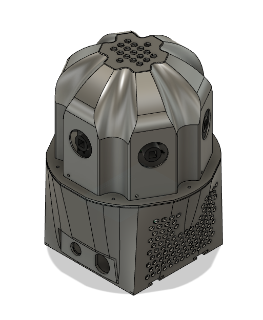
Overview
08/07/2023 at 18:36 • 0 commentsI have been exploring the possibility of creating a 360 camera for street motion capture for a while. It all started with an article I came across on the internet about Surround360 - a solution that was designed and released as open-source by the Facebook team a few years ago. Unfortunately, the solution turned out to be far from budget-friendly: by the most optimistic estimates, assembling the setup would cost around $30,000.
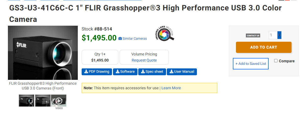
The Facebook design includes certain extravagances, which, if eliminated, could significantly reduce the cost of the construction. For instance, the use of 14 cameras in a circular arrangement is justified for capturing depth information and subsequent processing, but it is entirely excessive for capturing urban street scenes.

Surround360 camera design. Using the ready-made GS3-U3-41c6c-c module ($1,500/unit) simplifies the assembly and configuration of the camera, but it really hits the wallet hard.
![]()
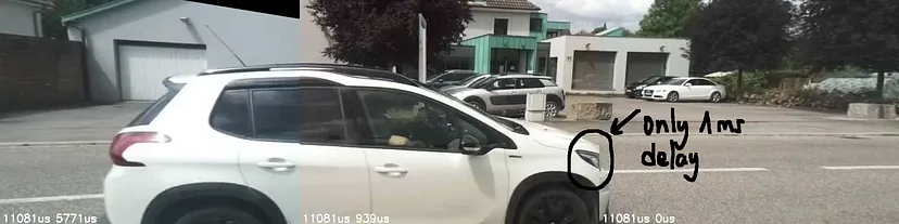
On the other hand, when aiming for cost reduction, it's crucial to maintain camera synchronization. Even a slight delay of a few milliseconds can impact the quality of the stitched panorama.
![]()
Achieving perfect synchronization is possible with Global Shutter cameras, but such cameras are much more expensive than the conventional Rolling Shutter ones, and their resolution is lower. Fortunately, Sony offers a solution for synchronizing N Rolling Shutter cameras in their sensors. It's available, for example, for IMX415 or IMX477 sensors, and it's precisely the latter sensor that will be used in this project.
---------- more ----------The Raspberry Pi High-Quality Camera module is quite old and provides a RAW image output, unlike its counterparts from OmniVision, for example. RAW means that the receiving end of the image will need to analyze it and provide "feedback" to the sensor in the form of exposure settings, white balance, and autofocus. When it comes to autofocus on the RPI HQ camera, it's straightforward: the focus is mechanically adjusted once for the entire sensor's lifespan. However, exposure and white balance will still need to be configured. Solutions can be purely software-based or include hardware acceleration.
My first prototype of 360 camera was made of 6 raspberry pi zero cameras and single board which aggregated the received data.
![]()
However, quite soon I found that this design has a lot of flaws:
- each RPI board has h264 encoder limit of 1080p which cannot handle full 12MP resolution;
- without h264 encoding there is no way to save raw data on single or even different SD cards with good FPS rate;
- power consumption of 7 boards becomes a pain and hell of wires.
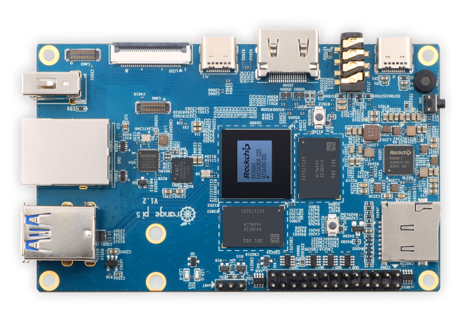
All that said, I desided to move to another SOC instead of RPI. Luckaly, RockChip recently presented the rk3588s SoC which has 3 mipi-csi2 connectors on a single board and NVME slot, which makes it almost ideal candidate for a control board, allowing to control up to 8 cameras with only two boards.
![]()
OrangePI sells 8Gb version of PI 5 board for only 90$ each, making it the cheapest board currently available on market with this type of characteristics.
When using single-board computer cameras, sooner or later you encounter the MIPI CSI-2 standard. This standard has been around for a while and is widely used, for example, in mobile phones. The nuance, however, is that manufacturers independently choose the connectors for these cameras.
Even Raspberry Pi, in its boards, uses two different connectors: one with 15 pins and another with 22 pins. In theory, the 22-pin connector can support 4 MIPI lanes instead of two (which means transmitting twice the number of frames), but in practice, on the PI Zero, the additional two lanes are simply not wired.
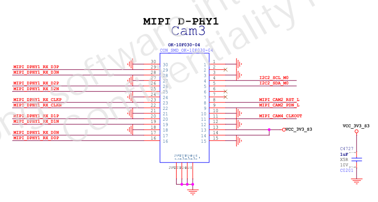
The manufacturer of the OPI 5 thoughtfully released the pinout diagram of the connections used on the board, making it available to the public.
![]()
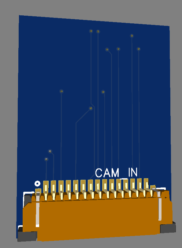
Let's quickly draft a diagram for the simplest adapter from one interface to another, order it from JLCPCB, simultaneously purchasing a dozen connectors from Aliexpress. We'll put everything together and realize that nothing is working.
![]()
After studying another dozen PDFs with watermarked "confidential!11" labels, we'll find our mistakes:
- RPI uses a logic level of 3.3V for I2C, while the OPI uses 1.8V.
- the same voltage level issue exists with pins 11 and 12 of the camera, which control the power.
- RK3588s board does not have any driver for IMX477.
That would be our next steps:
- create Rockchip-compatible driver for IMX477.
- create hardware adapter allowing to connect RPI HQ camera to OPI 5 board.
Open360Camera
Building professional-quality 360 street photography camera with consumer components.