Close
0%
0%

Relatively Universal ROM Programmer

EPROM programmer too expensive? This isn't!

Similar projects worth following
Should an EEPROM programmer really be 70$? No.
We need a way to program cheap old grab bag ROMs without needing a programmer that ruins the financial incentive to reuse and recycle old ROMs... and this is the way!

With the Relatively Universal ROM Programmer you can program 24, 28 and 32 pin ROMs that need 5-27V erasure or programming voltages, for the price of less than 10$! Gear up!

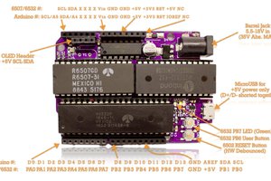
It comes in an Arduino shield form factor for easy interfacing with a bunch of things.

UPDATE! It's now available as a kit, here: https://www.imania.dk/samlesaet-hobbyelektronik-og-ic-er.htm

Using three 573 registers for addressing the 16 address lines of a 64K ROM the #Relatively Universal ROM Programmer should be able to handle most ROMs, even using a development board with a modest pin count.

It comes with a boost regulator to provide 14V erasure voltage (actually anywhere from 4.5->36V-ish) and 12V programming voltage for the more old school varieties, but it's also meant to be a cheap way to program more friendly ROMs like the typical 5V programming ones. 

It uses simple bjt drivers for switching VPP/VEP at minimum cost. 

Since there are quite a lot of different ROMs out there that share pin counts, but might not share timing details etc, the software part is currently up to the appetite of the hacker using it, coming in several different varieties. 6502 assembly routines are provided for the basics, an Arduino sketch with support for a few ROMs(including standalone blank checking and erasure), and finally an easy to use third party firmware and Python app with support for 100s of different (E(E))PROMs and Flash ROMs

After a year of development the Relatively Universal ROM Programmer is certainly a contender for the title of a hacker's favorite ROM programmer. 

Here's the Revision 2 announcement:

Here's the kit announcement:

Here's a part of the build process..

universalprogrammer.pdf

Initial schematic

Adobe Portable Document Format - 74.08 kB - 08/07/2023 at 21:40

Preview

  • 1 × PCB Electronic Components / Misc. Electronic Components
  • 1 × 28 pin DIP socket or ZIF socket
  • 3 × 74HC573 Registers Electronic Components / Misc. Electronic Components
  • 1 × SOT-23-5 Boost regulator AP3012 for instance
  • 4 × SOT-23 NPN BJT

View all 8 components

  • Safer, better, hackier!

    Anders Nielsen2 days ago 0 comments

    Relatively Universal ROM Programmer – Project Update!

    I’m so thrilled about the progress we’ve made on the Relatively Universal ROM Programmer! This tool has become indispensable for so many, and I couldn’t have done it without all of you. From retro computing enthusiasts to synth tinkerers and breadboard experimenters, your enthusiasm and feedback have been incredible. Hearing how this project is being used worldwide is what makes working on it so rewarding.

    Updates and Improvements

    Revision 2: Immediate Sell-Out and Feedback!

    Revision 2 of the programmer sold out almost immediately, thanks to the overwhelming interest. Alongside the new demand came fantastic feedback, with some ideas already making their way into the latest updates.

    Fixing the Feedback Loop and Voltage Control

    Special thanks to Kuba0040, who highlighted a potential issue with the feedback loop potentiometer on Revision 2. If the potentiometer is overturned, the wiper might lift, potentially causing a runaway condition in the regulator. While rare, this issue has been fixed by connecting the bottom of the pot to the wiper, making the design more robust.

    Video:

    On top of that, the feedback loop discussion opened up new possibilities for better control of the output voltage. While off-the-shelf DACs like I2C or SPI exist, they can cost more than the entire board—less than ideal for an affordable, open-source project. Instead, we’re exploring using an 8-bit DAC built with parallel registers, just like the ones already on the programmer. This approach is cost-effective and opens the door for digitally controlling the programming voltage.

    For now, Revision 2.1 includes some solder jumper pads on the back of the board, allowing for easier adjustment of the voltage regulator feedback loop. Whether you need a higher default voltage (up to 25V for TMS2532-style ROMs) or want to experiment with digital control, the pads make it straightforward.

    Fused Regulator

    Revision 2.1 also includes a polyfuse on the programming voltage regulator input. The fuse, rated for 200mA, provides enough power for programming old ROMs while protecting the regulator and the ROM in the socket from accidental shorts. While it’s not foolproof (e.g., a reverse-inserted ROM might still cause damage), it’s a step in the right direction to keep the magic smoke inside.

    Firestarter Firmware Updates

    A big shoutout to Henrik Olsson, whose work on the Firestarter firmware and app has expanded compatibility to even more ROM types. With the latest updates, Firestarter now supports Flash-based ROMs like the SST39SF series, including the 4Mbit SST39SF040s, with software write protection built-in. Amazing work, Henrik!

    What’s Next?

    Digital voltage control is on the horizon, but it’s a few prototypes away from perfection. For now, Revision 2.1 is your go-to if you need a reliable programmer for old ROMs. The improvements make it more robust and user-friendly, even if we’re not yet fully digital.

    Why Choose the Relatively Universal ROM Programmer?

    Sure, commercial programmers like the TL866-II or T48 might be faster for certain tasks, but this project is about openness, repairability, and community. If something breaks, you can fix it. Plus, the ongoing community support makes this much more than just a tool—it’s a platform for experimentation and learning.

    Rev 2.1 is for sale over @ iMania.dk for less than $9.

  • This ROM Burner is getting popular!

    Anders Nielsen06/08/2024 at 21:32 0 comments

    I'm blown away by the success of my little project here! 

    The Youtube audience liked it so much it sold out the first time over the first weekend, and by the looks of it the second batch will sell out tomorrow. 

    Who would've thunk a 9$ E(E)PROM programmer would be popular? :)

    I guess it does help that it now has actual software that'll take a ROM file via serial and burn it - and even has a few standalone features for identifying a ROM etc. 

    I say it better in this video...

  • Boards on the way!

    Anders Nielsen04/10/2024 at 08:50 5 comments

    I'm super happy to announce boards are now on the way - I'm also a bit scared they won't work, but at least in theory they should work. 
    And if they do, that will officially make them the cheapest 21V EPROM programmer on the planet @ < 10$ 🎉👾

    Anyway, here's how they're supposed to work: 

  • Slow and steady wins the race

    Anders Nielsen03/30/2024 at 19:24 3 comments

    Things are moving along and I managed to program both a W27C512 and a M2732A - the latter requires a 21V programming pulse, so if we can program that, we're probably ready to get a move on with a PCB. 

    6502 assembly code has enough routines to check ID's, erase EEPROMs (including 14V erase), and program with either 1-255ms programming pulses or 100us. 

    I'm confident the hardware works, so now it's just a matter of committing traces to a PCB. Spending a lot of time getting the layout right, at the moment. 

    I have a sponsorship lined up for PCBs and components, so the first 100 or so will be available cheap or really really cheap. 

    Oh - and I also messed around with undoing my new 21V EPROM programming skills. Have a look if you haven't seen the video. 

  • Registers! >>> Speeed boost!

    Anders Nielsen09/12/2023 at 11:13 1 comment

    Schematic has been updated and pushed to Github. Instructions added here.

    Switching from shift registers to plain registers and muxing the data bus we should get a pretty good speed boost. Thanks to @Ken Yap for the upgrade idea!

    I've yet to finish routing the PCB but the concept is ready for some actual testing. 

    Time to stress test it on a breadboard! :)

  • Status update! #self.replicate

    Anders Nielsen08/07/2023 at 22:26 0 comments

    The project started a few months ago as a forum thread on 6502.org

    The project has taken a bit of shape, I've made the initial schematic and started designing the PCB. Before finishing the PCB the project needs a bit more time on the breadboard.

    The idea is sound and deserves the work to be put in - even if it ends up being a bit slower than the commercial programmers. Cheap and easy to make is the goal!

    Arduino seems like a reasonable platform to write some code for, but on the other hand it might be a lot of fun to make the #65uino self-replicating by letting it program it's own ROMs - especially since it has no problem reading out the whole ROM that's currently in the socket - but maybe thats more a log for that project :D

    I'm aiming at 1/8th the price point of a commercial programmer(in parts) - we'll see if that's possible. 

  • We need a cheap ROM burner!

    Anders Nielsen08/07/2023 at 21:49 0 comments

    Frustrated with the fact that you can easily get a bag full of W27C512 EEPROMs for single digit $'s, but you need a 70$ programmer I decided to make this!

    It's supposed to plug into a host dev board, like a #65uino or other dev board and should program a wide range of electrically erasable (or just erasable) ROMs. 

    I'm not sure how much I'll have ready for the 2023 Hackaday Prize, but it's still a good excuse to get some open hardware out the door!

    P.S. Software not included for now

View all 7 project logs

  • 1
    Send gerber files from Kicad project on Github to your favorite board house
  • 2
    Solder away!
  • 3
    Attach to Arduino form factor dev board and get coding

View all 4 instructions

Enjoy this project?

Share

Discussions

Mike wrote 10/08/2024 at 11:05 point

I got the programmer from iMania. Works perfectly. The only thing is I'd like to have a detailed description of jumper configuration. Is that possible?
My main concern is how to supply vpe instead of vpp to the chip (I need 21V) and what are the goldpins beneath A0 pin?

  Are you sure? yes | no

Thomas wrote 09/16/2024 at 07:25 point

I ended up building my own, but coding it was a real challenge. I found that getting a bit of help with programming assignments from https://essays.edubirdie.com/programming-assignment-help made a big difference. It’s handy for those tricky parts where you need extra guidance. If you’re tackling something complex, a little expert advice can really help you get past those roadblocks.

  Are you sure? yes | no

Timo wrote 10/11/2023 at 13:39 point

Nice project, i need a ROM Programmer for myself and i am kind of hopeful on this one. However, in the schematic you connected D0 and D1 of the ROM to Pin 15 and 16 of the MCU/Arduino. Iguess these pins are required for the USB connection to the PC. I guess you can work around that in software, but maybe its a good idea to leave pin 15 and 16 of the arduino open. 

Just a thought.

  Are you sure? yes | no

Anders Nielsen wrote 10/11/2023 at 15:51 point

Yeah, I don't really see any way around that - on the Arduino Uno/328p the only fully available 8 bit port is PORTD (D0->D7) and the performance hit of not using it is that we have to do bit juggling with half of another port for instance.. Reducing speed drastically. 
Setting "PORTD = value" is very fast and we can still use the serial port via USB - just not at the same time. 
At least we won't have to unplug the RUROMP(better acronym pending) to reprogram the Arduino.

  Are you sure? yes | no

Timo wrote 10/11/2023 at 16:56 point

Are you using the Arduino Library? If yes, you are probably right. 

But, if you are using plain C, the increase in time per byte is 3 clock cycles. Just shifting out the 16 adress bits will take at least 32 clock cycles. Plus some over head.

In total your performance hit will probably be below 5%.

Lets assume it takes 100 cycles to write one byte to the EPROM. The maximum amount of bytes you can write is 2^16 (all available adresses), then it takes roughly 6.5 million cycles to write all the date. At a clock rate of 16MHz (typical Arduino clock) this takes 0.4 seconds.

I don't think you have a performance issue.

  Are you sure? yes | no

Anders Nielsen wrote 10/20/2023 at 14:42 point

I think you missed the switch to parallel registers - one byte is just load lower address byte, clock, load data byte, clock - and every 256 bytes also a higher address byte clock. Much more efficient - and the goal is also to make it usable on my 1 MHz #65uino  :) 

  Are you sure? yes | no

Timo wrote 11/02/2023 at 17:15 point

Ah, right. ^^

  Are you sure? yes | no

Ken Yap wrote 08/08/2023 at 03:40 point

In fact thinking a bit about it, muxing address and data on the bus isn't that much more complicated. Instead of the 595s you'd have a couple of latched register chips, and instead of the 595 drive lines you'd have the mux control lines which would be at minimum: data/address, low/high byte, and load.

  Are you sure? yes | no

Anders Nielsen wrote 08/08/2023 at 05:31 point

Thanks you for the input! The idea with using the 595's instead of 590's is "fast" arbitrary address selection and using a single MCU register for data increases data speed and makes it bi-directional. 

What register IC's did you have in mind?

  Are you sure? yes | no

Ken Yap wrote 08/08/2023 at 05:38 point

I think the good old 74x573 octal latch will work fine and is cheap enough.

  Are you sure? yes | no

Anders Nielsen wrote 08/09/2023 at 10:22 point

So, muxing by using a single port on the mcu and three registers for data/address?  Or another for control bits, like VEP/VPP enable?
I guess that needs another pin for data bus latch+enable. Hmm. 
That would also require another input register for reading the ROM, right?

  Are you sure? yes | no

Ken Yap wrote 08/09/2023 at 12:37 point

You only need a couple of octal latches for the address, similar to the couple of octal shift registers. The data lines of the EPROM can be driven directly by the Arduino. Their state only matters at the time you pulse the program pin. They need to be bidirectional anyway so that you can read back the EPROM, just like in the shift register case. The other lines like program voltage enable are already needed.

  Are you sure? yes | no

Anders Nielsen wrote 08/09/2023 at 12:55 point

Yes, that'll work - about the same amount of pins but should be faster than clocking serially. Especially a lot faster on the 1MHz #65uino 

  Are you sure? yes | no

Ken Yap wrote 08/09/2023 at 13:03 point

👍

  Are you sure? yes | no

Ken Yap wrote 08/10/2023 at 00:35 point

Additional speedup can be obtained by noting that the upper byte of the address needs to be changed only after 256 bytes of data because only the lower byte of the address changes. So one low address byte load 255/256 of the time.

In practice this is simple. The driving software checks if the upper byte is the same as the last time and doesn't load it if it hasn't changed.

  Are you sure? yes | no

Ken Yap wrote 08/10/2023 at 05:49 point

In fact this "caching" could even work for the low byte. Say the EPROM burning protocol does verify after write. For the read-back, there's no need to change the address at all. All this can be encapsulated in a routine in the burning software.

  Are you sure? yes | no

Anders Nielsen wrote 08/14/2023 at 11:54 point

@Ken Yap Yes! That should make it way more efficient. Especially in 6502 assembly on the 65uino.
It's a little bit frustrating the only whole port available on an Arduino Uno footprint is the same port that uses the two lower bits for serial data (PORTD)..
For the 65uino it's easy to swap the software serial pins to use the other port (usually occupied by i2c SLC/SDA) but for an Arduino Uno with hardware serial on port D, I'm not sure what the best solution is. 
Eventually I expect the data for the ROM to come from somewhere off board ;-)

  Are you sure? yes | no

Ken Yap wrote 08/14/2023 at 12:56 point

I think it's not so bad if you can arrange to use the same top or bottom nybble of two ports, then in betwen the port writes you do a swap nybble. Anyway the AVR is fast enough. The data is definitely a problem for the Arduino as the onboard RAM isn't enough if one is going to burn the whole 64kB EPROM, so some sort of comms with a host computer will be needed to send a chunk at a time. Or a SD card.

  Are you sure? yes | no

Ken Yap wrote 08/08/2023 at 00:18 point

Another idea might be to multiplex the address and data onto one bus from the Arduino, getting the Arduino to write and latch 2 bytes to the address register.

  Are you sure? yes | no

Ken Yap wrote 08/08/2023 at 00:14 point

This is an excellent idea. I wonder how much slowdown having the load each address serially imposes on the programming time. I suppose a hobbyist shouldn't mind waiting. I wonder how many more chips would be required to put a counter on the board, then the software would just reset the counter at the beginning then step through each address.

  Are you sure? yes | no

Similar Projects

Does this project spark your interest?

Become a member to follow this project and never miss any updates