Guyrandy Jean-Gilles
-
The Last Update
07/17/2024 at 01:43 • 0 commentsLast update, I talked about choosing embedded Linux over a micro-controller to continue this project and how I would be playing with Buildroot to better understand that system. I've done that and WOW! (Almost) all the firmware functionality you've ever wanted has been pre-written for you to use for free... if you figure out how to configure the kernel. Getting a bare image of Buildroot is fairly straight forward, but I got lost in configuration hell trying to setup all the peripherals on the existing prototype.
This made me take a step back and ask why I was down this path. The whole reason I had decided on embedded Linux vs a micro-controller was adding audio to the project would require more than userspace GPIO manipulation. After investigating other commercial e-readers, almost none of them have a 3.5mm audio jack, but instead rely on connection to a Bluetooth device. This is the route I went, and by the time you're reading this, the project description will be updated with exactly how this is done.
This is the last update because the project does everything I want it to do at this point. It can read ebooks, play audiobooks, and sync with a remote server to download books. It is by no means polished, but it's the proof of concept I wanted to make when I began this idea.
-
The Biggest Limitation to a Micro-controller Based E-reader
04/17/2024 at 16:24 • 0 commentsLast project log I discussed trying to reduce MuPDF to a size that could fit on memory reasonable for a micro-controller. Thankfully, the library's maintainers designed it so including or removing certain modules is as simple as changing a single configuration file. With the help of the maintainers, and their excellent documentation, I quickly realized that the size of the library is not due to the code itself but an artifact of the fonts included.
Removing all the fonts dropped a test program (desktop, not embedded) from 40MB to 5MB with no other optimizations. Now, an e-reader with no fonts is not very useful. So I looked for small font families and slammed into a old problem. As of writing this, Unicode contains 149,878 characters. However, only 65,535 characters can be in a True Type font file. As a result, no single font family can represent all Unicode text an e-reader might encounter from an arbitrary book file.
There are attempts to make a uniform typeface for all writing systems like Google Noto or GNU Unifont. But, for example, all the GNU Unifont OpenType fonts are ~12MB and the Google Noto fonts are ~10MB. Even ambitious projects like Joey Castillo's Babel use 2MB to represent Unicode's basic multilingual plane (65,520/149,878 characters as of version 15). EPDiy, an ESP32-based e-Reader project, requires editing the source to add or change fonts. Other generic micro-controller font libraries, like OpenFontRender for the Arduino ecosystem, MCUFont, or mcu-renderer require preprocessing the fonts on the host machine before programming the target device--almost always reducing the subset of characters that can be rendered.
Simply put, fonts take a lot of storage. A micro-controller certainly can represent all the Unicode characters, but, given the low resource environment, it makes the most sense to limit the characters that can be rendered.
I started down this path to decide if I should continue this project with a embedded Linux system or with a micro-controller system. Given the project's goal: democratizing e-books, supporting as many characters sets as possible is a priority. Thus embedded Linux is the better path to follow.
My first step down this path is getting familiar with Buildroot, a tool that simplifies embedded Linux configuration. There are lots of examples for the Raspberry Pi boards, but I plan on eventually moving away from them to a custom board with a different chipset. There probably won't be any new hardware or software features for a while as I figure out Buildroot. Maybe I'll write up a getting started guide once I find a configuration I like. We'll see. Wish me luck.
-
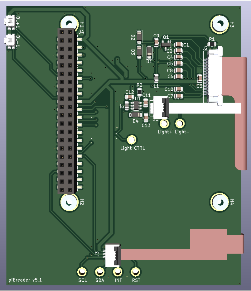
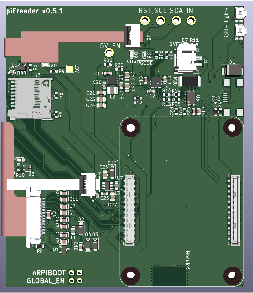
Bringing Up Version 0.5.1
03/31/2024 at 20:19 • 0 commentsI sent this version to fab in November of 2023, but didn't finish bringing up major board components until recently.
---------- more ----------Past Bringup
I've scattered board bring up progress in previous updates, but I'll repeat previous conclusions here:
- The USB micro connector I chose cannot be soldered to a board, so I have to change the footprint.
- The 24-pin FPC connector is too close to the board edge given the dimensions of the e-paper's ribbon cable, so I need to move it back ~2mm.
- The surface mount JST connector on the carrier board layout is so tight I need pliers to remove the battery. I need to replace it with a looser fighting connector.
Frontlight Dimming
I've been calling the light panel on the GDEY042T81-FT02 a "backlight", but physically, it is a front light. I complained about dimming it with the TPS61165, but it turns out all I had to do was increase the PWM frequency to within in the ICs documented specifications. I continued to see problems after increasing the frequency when connecting the Raspberry Pi GPIO to the piEreader HAT PCB with jumper wires, though. Once I directly put the piEreader HAT on a Raspberry Pi, I no longer saw dimming issues. Probably due to increased impedance from the jumper wires.
Battery Monitoring
I was able to read parameters from the BQ27441 IC when connected to the Sparkfun Battery Babysitter . I wasn't getting sensible readings from the piEreader carrier board because of a stupid schematic error.
![]()
You'll notice that the
SDAandSCLpins on the BQ27441 aren't actually connected to the I2C pins of the CM4 module. They're just pulled up to 3v3. A stupid mistake. Again the code works on the Babysitter development board, but correcting battery status will require a board rev.Luckily I placed status LEDs on the BQ24075 IC. Directly connecting the 5V and GND pads to a DC power supply resulted in expect behavior from the power good, battery present, and charging LEDs.
Next Steps
Previously I've talked about adding audio to the project. After doing some research, it looks like this will require fiddling with Linux configuration to make things work. I'm not against this, but I'm still not convinced a Linux board is the best platform for this project. The decision that forks the road to embedded Linux or a micro-controller is minimizing MuPDF to a size that can fit on a low resource platform. This won't be easy and might not even be possible, but that will be my focus for the time being.
For the latest hardware and software updates please visit the project's repository.
-
GUI Based Wifi Configuration
02/29/2024 at 05:42 • 0 commentsSoftware
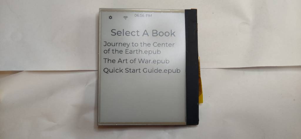
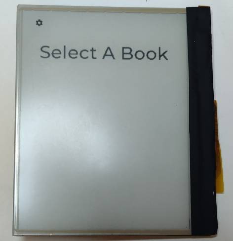
Despite the title, this is a hodge-podge update. The first concrete achievement I can boast is two new additions to the status bar: a clock and a Wifi menu.
---------- more ----------![]()
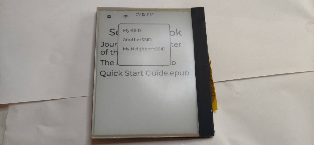
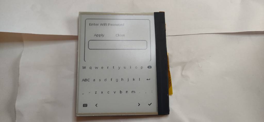
The clock is self explanatory. The Wifi menu will list the available networks when tapped and will prompt a password entry once you select a network.
![]()
![]()
Behind the scenes, the code is using nmcli to connect to the aforementioned network. Right now the password is being sent in plain text over the command line, but I really should be inputting text via stdin. That'll change by the next revision.
Hardware
I finally got around to troubleshooting with the TPS61165 evaluation kit. I'm still troubleshooting, but I can dim on the piEreader hardware, but things still aren't working exactly as I expect. I'll probably make a dedicated dev log to explain everything that's gone wrong.
I don't want to do another board revision until I iron out the dimming problem, but I will absolutely have to fix the USB connector. Somehow I picked a connector who's pins don't sit flush on the PCB.
![]()
It may not show up well on camera, but there's no way to solder the connector onto the board. I couldn't have known until I tried to do so myself. A USB connector isn't enough to justify a board spin, so I'll leave things as is right now.
Next Steps
Last log I talked about supporting audiobooks and the need to switch from
bcm2835library to do so. I actually have a version of firmware usinglgpioand it was sloooooooooow, so I don't want to rely on it. Also, after reading the documentation for thepigpiolibrary, it seems like using PWM to dim will always block the Raspberry Pi from producing audio. So that gives me two options hardware wise: 1) Change hardware platforms 2) Use the TPS61165 (or some other chip's) serial protocol, EasyScale, to dim the backlight. It makes sense to at least try to implement EasyScale as that should be quicker than switching hardware.I also still need to write firmware for the battery fuel guage but that will always be incomplete without the a USB connector. Either way, the decisions moving forward are focused on supporting audiobooks.
For the most recent software and hardware changes, please check the project's repository.
-
User-Defined Book Servers
01/31/2024 at 02:03 • 0 commentsHappy New Year! I didn't work on this project much during the holidays and I realized I've had at least one project update a month since keeping this log. So I thought I'd put together what I've been working on. This will entirely be a software update and, as of writing this, the code is still in the development branch because it's not the cleanest implementation, but it's functional.
---------- more ----------New UI Elements
If you're new to the project, you'll know one of the goals is to allow a book lover to connect their eReader to any book server of their choosing. Before the most recent code changes, book lovers had to hand edit a line of Python code.
def __init__(self, url: str = "http://192.168.1.193:8080/opds"):
The
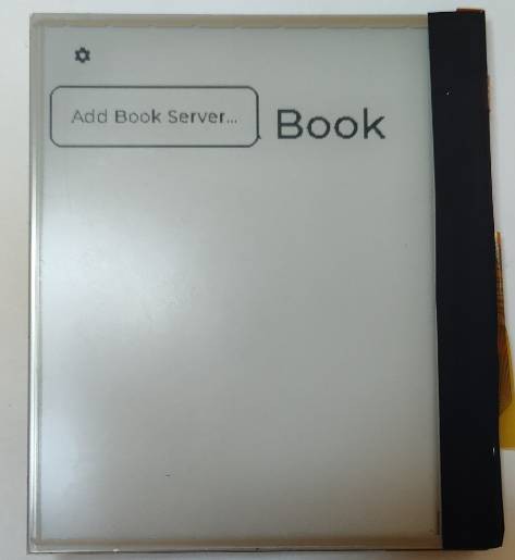
urlargument was hard-coded. There are multiple problems with this. First, a book lover has no way of knowing where to make this edit without reading source code. Second, there is no way to change the url through the UI. Third, only one server can be connected to.Recent code changes added a status bar to the UI that has one option in the settings menu: Add Book Server.
![]()
![]()
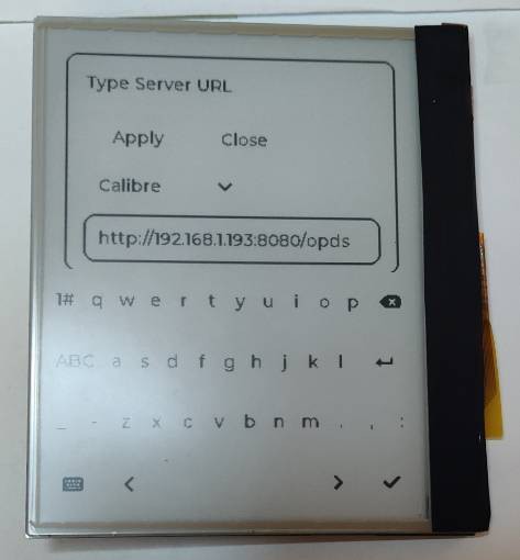
The settings icon is an intuitive UI element and the "Add Book Server" menu option is self-explanatory; much less obtuse than editing the Python code above. The form to add a book server is... less aesthetic.
![]()
I'm not a graphic designer, but the form is functional and adds the book server to a list of urls in a file at
$XDG_CONFIG_HOME/piereader/config.json. The config file looks like this:{ "book_directory": "/home/ereader/Bookshelf/", "bookservers": [ "http://192.168.1.193:8080/opds", "mybookserverdomain.com" ] }For context, it took me 3 minutes to type
http://192.168.1.193:8080/opdsusing the virtual keyboard and that was with partial refresh enabled. A tech savvy book lover would be better off ssh-ing into the device and editing the above file, but if that's not an option, now there is a way to do it through the UI.Right now, only Calibre servers are implemented, but more server types will be added in the future.
Under The Hood
Except for the Python code mentioned above, the entire project is written in C. The new server form calls the Python code to download books and access the book servers. Both the C and Python had to be refactored to accommodate for this communication. I won't say the implementation is good. In fact, I think this portion of the project should be refactored for better data flow. I really didn't plan out the system architecture at all as I was focused on connecting the book rendering libraries to the GUI framework and the ePaper driver.
Right now, there is a five second timer that checks if there are un-downloaded books available from the known list of servers. Again, the messages sent between the UI elements and between C and Python are not the cleanest. But it's functional and there's a long list of tasks to work on.
Next steps
Now that there's a status bar and virtual keyboard, I can add things like a clock, WiFI entry, battery status, power settings, etc. That said, I've made a habit of working on software as PCBs are manufactured since that's an effective use of lead times. The hardware changes in the backlog are:
- Adding audio
- Switching to a ePaper with more grayscale bits
- Making a custom Linux board/moving to a micro-controller
There's a hard blocker for adding audio since using PWM (which dims the back-light) with the bcm2835 library requires turning audio off. I'll have to control the back-light with the proprietary serial protocol of the TPS61165. I still have yet to trouble shoot the back-light not dimming, but the development boards have come in so I can move forward there.
Drastic hardware changes like moving away from the Raspberry Pi or to a micro-controller would be fun but wouldn't add a lot to the project that can't be done with current hardware. Adding audio opens the project up to audio books and podcasts and using a display with at least 4 levels of gray would open up the project to comics and manga.
For now I'll be writing software for inputting WiFI credentials, but the future of the project's hardware is still in flux.
For the latest hardware and firmware updates, please see the project's repository.
-
This eReader has a Touchscreen and Backlight!
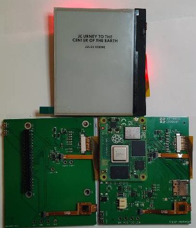
12/15/2023 at 00:05 • 0 commentsThe new CM4 and HAT PCBs for the GDEY042T81-FT02 are in and by and large they work. I still have to troubleshoot some hardware/firmware, but the project now has portable power, a touchscreen, and backlight.
---------- more ----------![]()
Portable Power
First, the 5V output being disabled is resolved in this version of the carrier board. You'll note in the above picture that there is no USB micro populated on the carrier board because of an error during manufacturing. I actually haven't tested charging on this specific version of the carrier board, but it's worked on previous boards so I'm not worried about it.
While still functional, the battery connector, S2B-PH-SM4-TB(LF)(SN), is really tight. So tight, that I have to use pliers to remove the battery once it's connected. I've only disconnected the battery a couple times but it's connector is already starting to deform. The dedicated lipo charger and boost converter I made used a through hole connector, B2B-PH-SM4-TB(LF)(SN), that doesn't mate as tightly. I'll switch out the part in the next revision.
I also realized a power switch, even if it isn't hardwired into the power rails, would be useful. Another change for the next next hardware revision.
Backlight
While the backlight works, for some reason I cannot get it to reliably dim with the new hardware. When connected to a DC power supply, the backlight dims as expected. But with the new PCBs, I can turn it off and turn it on, but I can't seem to consistently drive it at, say, 50% brightness. I haven't figured out why yet, but I did notice that the TPS61165 driver is drawing a TON of amperage. Around 300 mA worth and I believe it's causing a voltage drop on the HAT. On the carrier board, the TPS63701 boost converter is good up to 1.2A so there's nothing to worry about there.
Even when I power the new hardware with a 10A DC power supply, I'm still seeing unreliable dimming behavior. To rule out a software issue, I bought a development board for the TPS61165. There are also some forums topics that have promising discussion. I'll probably write up a different project log once I resolve the issue.
Also, when I insert a battery pack, the backlight turns on very briefly and then turns off. I think what's happening is the Raspberry Pi GPIO that connects to the control pin of the TPS61165 briefly is pulled high before becoming tri-stated. I plan on adding a weak pull down resistor to the TPS61165 control pin to prevent the blimp during battery insertion.
Ribbon Cables
You'll notice some contortion on the 24-pin ribbon cable in the picture above.I preemptively moved the 24-pin FFC connector closer to the edge of the board based on GDEY042T81-FT02's fitment on existing PCBs I had in hand. I'll probably have to move it back two millimeters or so to make things fit properly.
Next Steps
My next goal is to add a virtual keyboard to the project. I've already prototyped basic typing, but the full implementation will need partial refresh as each key press takes 1.5s. Also, I'm only using black and white for the GDEY042T81, but 4 color grayscale will allow pop overs on key presses and better contrast modals too.
There's also a new HAT+ form factor for the Raspberry Pi 5. I don't have one so I don't think I'll make a new board for it. I'm fairly content with the hardware right now, so most of the future updates will probably be firmware related.
For the latest hardware and firmware updates, please see the projects repository.
-
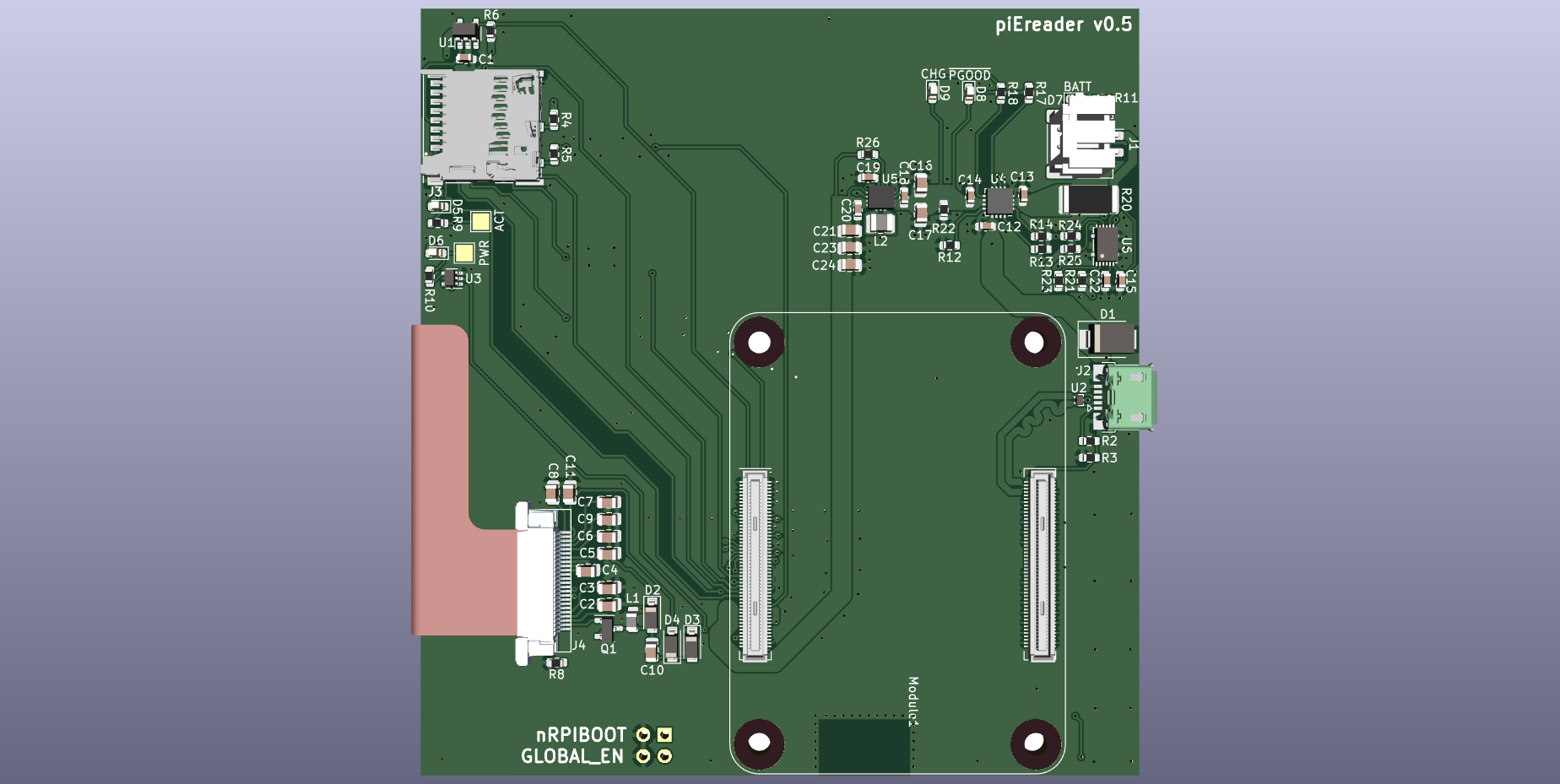
PCB Layout for GDEY042T81-FT02
11/24/2023 at 19:35 • 0 commentsThe latest PCB revision is on it's way to fabrication and there are lots of changes to note.
---------- more ----------![]()
![]()
First, GDEY042T81-FT02 replaces GDEW042T2 as the e-paper and also adds a touchscreen and back-light to the project. The touchscreen removes the need for navigation buttons, but I added two side-actuated buttons to physically control the back-light brightness.
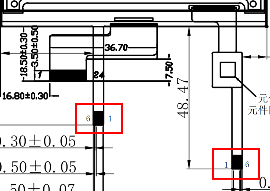
One easy thing to miss about GDEY042T81-FT02 is the touchscreen and back-light ribbon cables are the exact same dimension but reversed pin numbers.
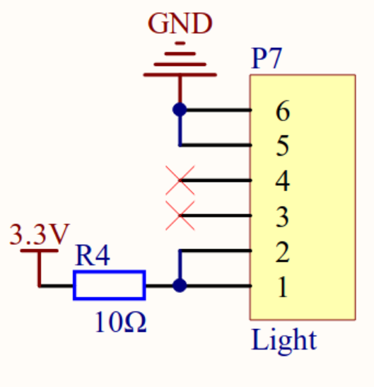
![]()
Both ribbon cables are 6 pin, 0.5mm pitch, but from left to right, the back-light pins are 6, 5, 4, 3, 2, 1, but the touchscreen pins from left to right are 1, 2, 3, 4, 5, 6. I'm not sure why it's designed like this. Especially since there are only two signals on the back-light ribbon. Pins 1 and 2 are LED+, pins 3 and 4 are unconnected, and pins 5 and 6 are LED-. Regardless, I made two different footprints with identical geometry but reversed pin-outs to accommodate for this weirdness.
For the carrier board, the SD card in the previous layout was conveniently placed exactly where the touchscreen ribbon cable lays.
![]()
![]()
I moved the status LEDs and SD card to accommodate for the touchscreen and back-light ribbon cables. Also, without the navigation buttons, the layout width is smaller and I had to move the USB micro connector further away from the computer\ module. The back-light brightness buttons also required shifting the portable power ICs and related components closer to the interior of the board.
Last layout update, I mentioned needing a sea of vias to route traces to the 100 pin Hirose connector. This problem became even worse with the addition of the touchscreen and back-light.
![]()
I joked previously about sticking to a 2 layer board to be frugal, but adding any other hardware will almost certainly require that I finally move to a 4 layer board.
Let's hope the this board is functional once it comes back from fabrication. For the most update code and hardware, please visit the project's repository.
-
Bringing Up GDEY042T81-FT02
11/09/2023 at 00:35 • 0 commentsI'll skip to the happy ending. I can drive the display, the back light, and can read data from the touch screen, but achieving those milestones took much much longer than it should've. This update won't have much info on the actual e-reader project but is more a
rantreflection on mistakes made while bringing up GDEY042T81-FT02 so I, and hopefully you, don't repeat them. Buckle up.---------- more ----------The Development Board
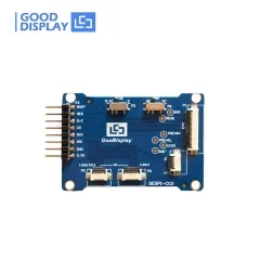
![photo of Good Display touchscreen development board]()
The DESPI-C03 development board has three sets of connectors. One for the e-paper display. One for the back light. Two for the touchscreens as they have different pinouts depending on the size you have. You would reasonably assume that connecting all three ribbon cables of GDEY042T81-FT02 to a single DESPI-C03 board would drive all the screen's components. That's what I did, but what I did was, in fact, wrong.
Everything worked as expected when I attached only the 24-pin e-paper ribbon cable to the development board. However, when I attached the 6-pin touch screen cable, the e-paper refused to update.
Mind you, I was not running any new code. The exact same firmware that drove the display perfectly didn't work properly when I connected the touchscreen ribbon cable. This led me to believe there was a hardware issue. So I examined the DESPI-C03's schematic.
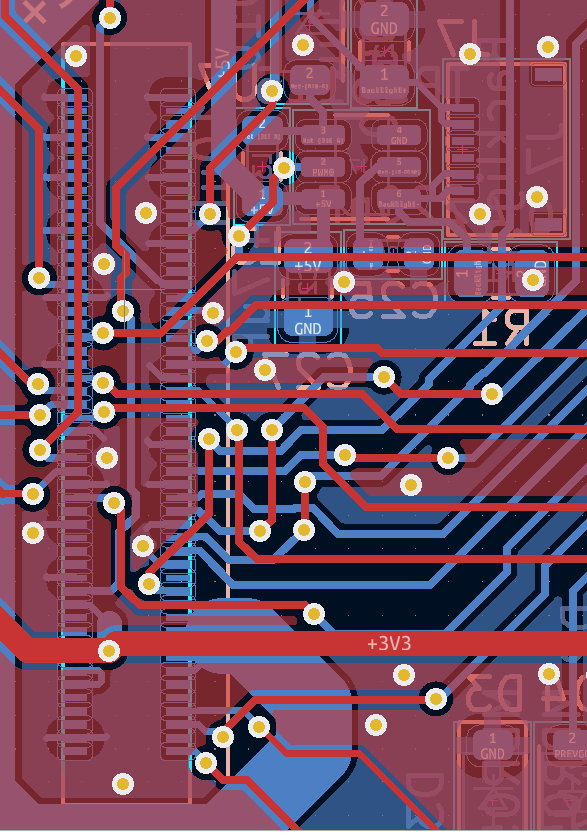
![]()
The labeling is extremely confusing but it looked like the same pins are used for SPI communication to the e-paper and I2C communication to the touchscreen. This would obviously cause problems. There's absolutely no warning of this on the DESPI-C03 silkscreen or on its product page. I only noticed because the demo video for the GDEY042T81-FT02 shows two separate development boards being used to drive the e-paper and read from the touchscreen.
Luckily, I bought two DESPI-C03 boards and had plenty of e-paper driver boards from earlier prototyping, but I wouldn't be surprised if other people weren't as lucky. But using two different DESPI-C03s did not resolve my issues.
The Touchscreen
If you're like me, you try to get vendor supplied code up and running before fiddling with any of you're own stuff. This way, when your custom written code evidently doesn't work, you can run the known, good vendor code as a sanity check. But the vendor code was the source of insanity.
Good Display provides several different example applications for Arduino, ESP32 (which was just Arduino-ESP32), STM32, etc. I had an ESP32 lying around so that's what I used to run the vendor code. Below is the content of that code's README in it's entirety.
SDA¡¢SCL---Have to be connected to a resistance to VCC

A0-INT
A3-RST
A4-SDA
A5-SCL
Sparse, but little documentation is better than no documentation. To translate, pin
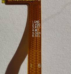
A0of the ESP32 should connect to theINTpin of the FT6336 (the IC that drives the touch screen), pinA3of the ESP32 should connect to theRSTpin of the FT6336, etc. I wired up my ESP32, DESPI-C03, and GDEY042T81-FT02 and... nothing. I quintuple checked the cryptic DESPI-C03 schematic but couldn't figure out what I was doing wrong. Eventually, I thought Good Display's code a lost cause and explored other FT6336 libraries for the ESP32. There are a couple to pick from, but I had the same problem. I couldn't read anything from the touchscreen no matter what.I connected my ESP32 to a known good piece of I2C hardware just to make sure I wasn't going crazy and confirmed that my ESP32 hardware functioned. So why did the touchscreen not work? If you're guessing I had a wiring problem, you're absolutely right. I only realized this when I looked at the silkscreen on the ribbon cable.
![]()
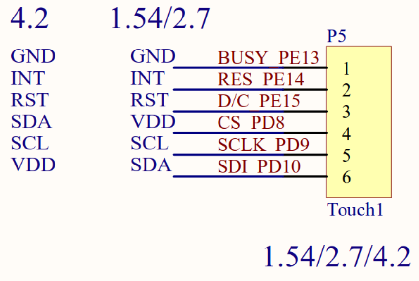
Pin 2 is supposed to be
VDDnot,INT. Pin 4 is supposed to beINTnotSDA. Pin 5 is supposed to beSDAnotSCL. Pin 6 is supposed to beSCLnotVDD. You can see how following the vendor's code documentation would result in problems. Worse, the silkscreen from DESPI-C03 does not warn of this potential miss-wiring at all. The correct wiring has FT6336'sGNDconnected to the DESPI-C03 pin labeledBUSY.VDDconnects toRES.RSTtoD/C.INTtoCS.SDAtoSCLK.SCLtoSDA. The DESPI-C03 silkscreen is useless with respect to wiring the touchscreen.I wasn't completely hopeless in discovering the wiring issue. The product page for the standalone touchscreen has the correct pinout. Is the touchscreen product page linked to the GDEY042T81-FT02 page? No. On the the DESPI-C03 page? No. I assume most people who bought the display and adapter without contacting an application engineer had to bumble in the dark like I did. But my failures did not end there.
I2C with BCM2835 Library
For some reason, the firmware that read data from the touchscreen would freeze. The whole Raspberry Pi wouldn't freeze; just the code. Killing and restarting the code would fix the problem until the next lock up. Sometimes it took ten seconds. Sometimes it took three minutes. But regardless, an e-reader wouldn't be very useful it freezes randomly whenever you touched the screen.
I shamelessly used trial and error to figure out an order function calls that would prevent a lock up. Here's a minimal example.
#include <bcm2835.h>

#define INT_PIN 6

uin8_t ft6336ReadByte(uint8_t address);

uint8_t main(void)
{
    while(1)
    {
        if (bcm2835_gpio_lev(INT_PIN) == 0)
        {
            /* FT6336 has an interrupt pin (INT_PIN) that pulls low
            * when there is touch data availabe
            */
            uin8_t touchData = ft6336ReadByte(0x4); // A data register of FT6336        }    }
}

uin8_t ft6336ReadByte(uint8_t address)
{
    uint8_t data = 0;
    bcm2835_i2c_begin();
    bcm2835_setSlaveAddress(0x38); // I2C address of FT6336
    bcm2835_i2c_set_baudrate(1000000);
    delayMs(10);
    bcm2835_i2c_write(&address, sizeof(address));
    bcm2835_i2c_read(&address, sizeof(data));
    bcm2835_end();
    return data;
}
Polling the FT6336 IC without checking its interrupt pin would eventually cause a lock up. Not delaying before writing and reading the IC would cause a lock up. Setting the target I2C address outside the super loop would cause a lock up. Same thing for the baudrate. For some reason, the above order of function calls would not cause a lockup. I left the code running for days and continuously touched the screen for 5+ minutes over a series of days, without stopping the loop, to make sure I could continuously read without a lockup. It's passed all my tests but I couldn't tell you why.
Note, I didn't see this problem with the ESP32. I only saw the code hanging when using the Raspberry Pi and the BCM2835 library. Also important to note that normal taps and swipes didn't cause any problems. I saw issues when I held and dragged my finger across the screen for extended periods of time. But because I couldn't consistently reproduce the freeze over the same time span with the faulty code, it made me worry the lock up might happen during normal e-reader operations.
I found two threads about this in the BCM2835 list serv. One dating back to 2015, the other as recent as June of 2023. The BCM2835 revision history shows a timeout check added to the I2C code for the most recent version (1.73),
So I upgraded the library to version 1.73 and I got even more errors. The new error
BCM2835_I2C_REASON_ERROR_TIMEOUTis returned for nearly every call ofbcm2835_i2c_write. Here's the thing, even when this error was returned, sometimes the data from FT6336 was correct. The data returned was only faulty whenBCM2835_I2C_REASON_ERROR_DATAwas returned. Remember, there were no errors with version 1.71 of the library and the touch data is always correct. I could just require the use of 1.71, but I wanted to discover the root cause of the problem.It was in line 1318 of
bcm2835.cunsigned long Failsafe = len * 1000;
lenis the length of data being read from the I2C sensor.Failsafecounts down during the loop where the bcm2835 library waits for a hardware response. IfFailsafereaches zero, the loop is broken without verifying a response from the peripheral. This behavior is specific to version 1.73 of the bcm2835 library. 1.71 doesn't have thisFailsafevariable. I suspect that, in most cases, the Pi is timing out mid transmission but the sensor finishes sending data during the cleanup processes after the timeout. Because version 1.71 doesn't have any timeouts, these mid transmission breaks didn't occur.Either way, if you want to use FT6336 with the bcm2835 library, stick to version 1.71.
Back-light
We return to the poorly designed DESPI-C03 for back-light woes. From the schematic, you'd think you'd only need to apply 3.3V for the back-light to turn on.
![]()
Wrong. This was actually the first thing I tried when I got the hardware, but it was the least important component to bring up, so I skipped it to work on the e-paper and touchscreen. After bumbling through the documentation for the latter, I decided to find the stand alone back-light product page.
- I discovered that the back light is actually 7 LEDs connected in series.
- The operating voltage of the front light is rated <= 21V.
- Good Display actually sells a dedicated front light driver that can output 9V, 12V, and 21V.
Is any of the above information on the GDEY042T81-FT02 page? Well actually, the front light voltage is mentioned as <=21V. But again, the DESPI-C03 schematic made me think 3.3V was fine. All the other information was no where to be found on the GDEY042T81-FT02 documentation.
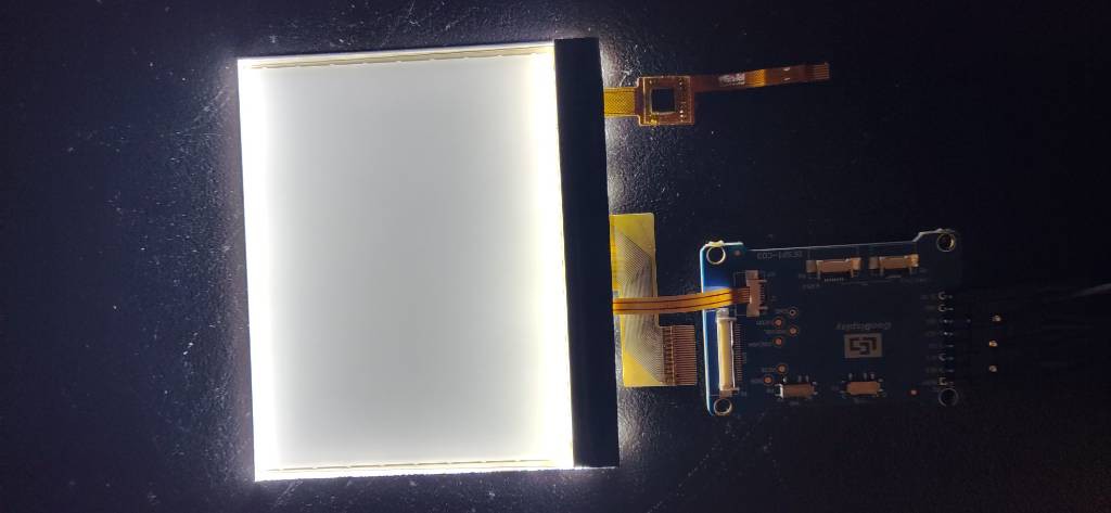
When I connected 21V directly to the back-light ribbon cable, bang! Let there be light!
![]()
Finally, all the components of the GDEY042T81-FT02 were verified functional.
</rant>
I hope you read this before trying to bring up GDEY042T81-FT02 yourself. If you're here after hitting a brick wall, I hope you haven't spent much time troubleshooting. If you're reading this after almost giving up on the hardware, join the club. We play DnD Thursday nights. Any way, the code is in the Gitlab repo. Use it as a known good reference because I certainly didn't have one.
If I would leave you with any lessons, it's that all documentation is wrong until proven otherwise.
-
The First Attempt at Portable Power
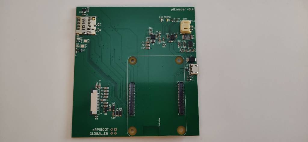
11/02/2023 at 13:19 • 0 commentsThe boards with lithium polymer charging are back and I've got mixed news: they mostly work. I ordered two (sponsored) designs from PCBWay: a dedicated lipo charger and a eReader carrier board with integrated lipo charging.
![]()
![]() ---------- more ----------
---------- more ----------Note how the SD card connector is properly orientated this revision, but is erroneously labeled "v0.4" instead of "v0.5".
The dedicated charger board works exactly as expected. I plug in a USB C cable and it outputs 5V and chargers a lipo battery if it's connected. If a battery is not connected, the board still outputs 5V. The eReader carrier board will charge a lipo battery if it's connected, however, it does not output 5V no matter what. Probing the board revealed that power from the USB micro connector was reaching the BQ24075 battery charger. That chip was even outputting power to the TPS63701 5V regulator. But the regulator didn't output anything. I reexamined the schematics for the dedicated lipo charger and eReader carrier board to eventually discover the problem.
Below is the schematic for the TPS63701 in the fully functional lipo charging board.
![]()
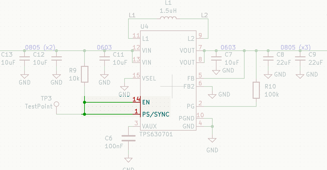
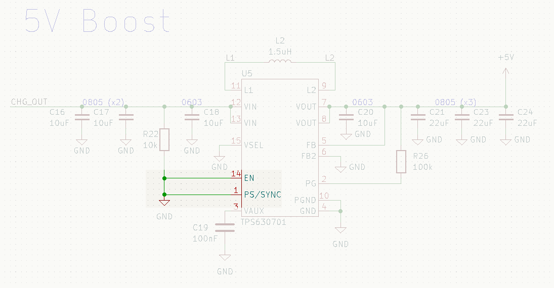
Below is the TPS63701 schematic for the faulty eReader carrier board.
![]()
For some reason, I grounded the enable pin (EN, pin 14) of the TPS63701 boost converter on the eReader carrier board but not the dedicated lipo charger. I couldn't tell you want was going through my head when I did that. I was able to emulate the same faulty 5V output behavior on the functional dedicated lipo charger by grounding that board's enable pin.
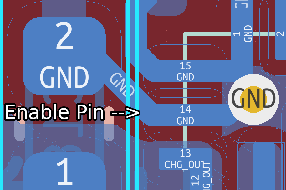
I considered trying to cut traces of the TPS63701's EN pin, but I simply don't have the tools to make modifications that small. Even if I did, the time and energy required to so would probably be best spent working on the long list of firmware I need to write and revving the layout to incorporate the new touchscreens that came in.
![]()
Unfortunately, the carrier boards are bricks. The first completely unusable hardware of this project. It took 5 revisions before it happened, so I consider that an accomplishment.
I've progressed in the bring up of GDEY042T81-FT02 enough to do a 6th hardware revision. And boy oh boy, was driving that touchscreen much more convoluted than it needed to be. But that's a project log for a different day.
For the latest status updates please visit the project's Gitlab repository.
-
A Much Needed Refactor
10/20/2023 at 04:49 • 0 commentsI'm still waiting on the latest hardware revision to manufacture, so in the mean time I've been refactoring the code to be more modular and follow separation of concerns. The requirement that forced this task was writing firmware for the GDEY042T81-FT02 touchscreen sub-assemblies from Good Display. Previously, the project relied on the structure of code from Waveshare for the GDEW042T2. Moving away from Waveshare's structure to thin abstractions will make porting Good Display's vendor code to this project much easier.
Here's an example. The project now has an abstraction layer for the e-paper aptly called "display.c/h" that contains the following function:
---------- more ----------#include "gdew042t2.h" ... static bool displayInit(void) { if(!gdew042t2Init()){ logError("Failed to initialize display"); return 0; } ... }"display.c" is the only file that includes "gdew042t2.h" in the entire project. Any other source files that need display functions include "display.h". This way, I only need to modify "display.c" to port the project to GDEY042T81. If all goes well, none of the function declarations need to change once the port is complete.
The files "gdew042t2.c/h" contain the specific implementations for that e-paper display. For example, the above function "gdew042t2Init" contains:
#include "gpio.h"
...
bool gdew042t2Init(void)
{
    // setup GPIO
    gpioSetMode(RESET_PIN, GPIO_OUTPUT);
    gpioSetMode(DC_PIN, GPIO_OUTPUT);
    gpioSetMode(CS_PIN, GPIO_OUTPUT);
    gpioSetMode(POWER_PIN, GPIO_OUTPUT);
    gpioSetMode(BUSY_PIN, GPIO_INPUT);
    ...
}
"gpio.h" is also an abstraction layer for low level GPIO manipulation. I.e the function "gpioSetMode" is:
#include "raspberrypi.h"
...
void gpioSetMode(uint32_t pin, uint8_t mode){
	return rpiGpioSetMode((uint8_t)pin, mode);
}
If you guessed that "raspberrypi.h" was another abstraction layer, you're right. The above "gpioSetMode" is a thin wrapper for the bcm2835 library.
#include <bcm2835.h>
void rpiGpioSetMode(uint8_t pin, uint8_t mode)
{
	if (mode == RPI_GPIO_INPUT){
		bcm2835_gpio_fsel(pin, BCM2835_GPIO_FSEL_INPT);
		return;
	}
	bcm2835_gpio_fsel(pin, BCM2835_GPIO_FSEL_OUTP);
}
It's abstraction layers all the way down! You might think this over kill, but code is read more than it's written. And I want to churn as little as possible. "raspberrypi.c/h" will probably never change for the rest of the project's history. "gdew042t2.c/h" will also probably never change again. Moving that code into separate files prevents churn and makes porting much easier as described above.
For the latest status updates please visit the project's Gitlab repository.
FLOSS Book Serving System
An open-source ereader that can display books from an open, self-hosted server