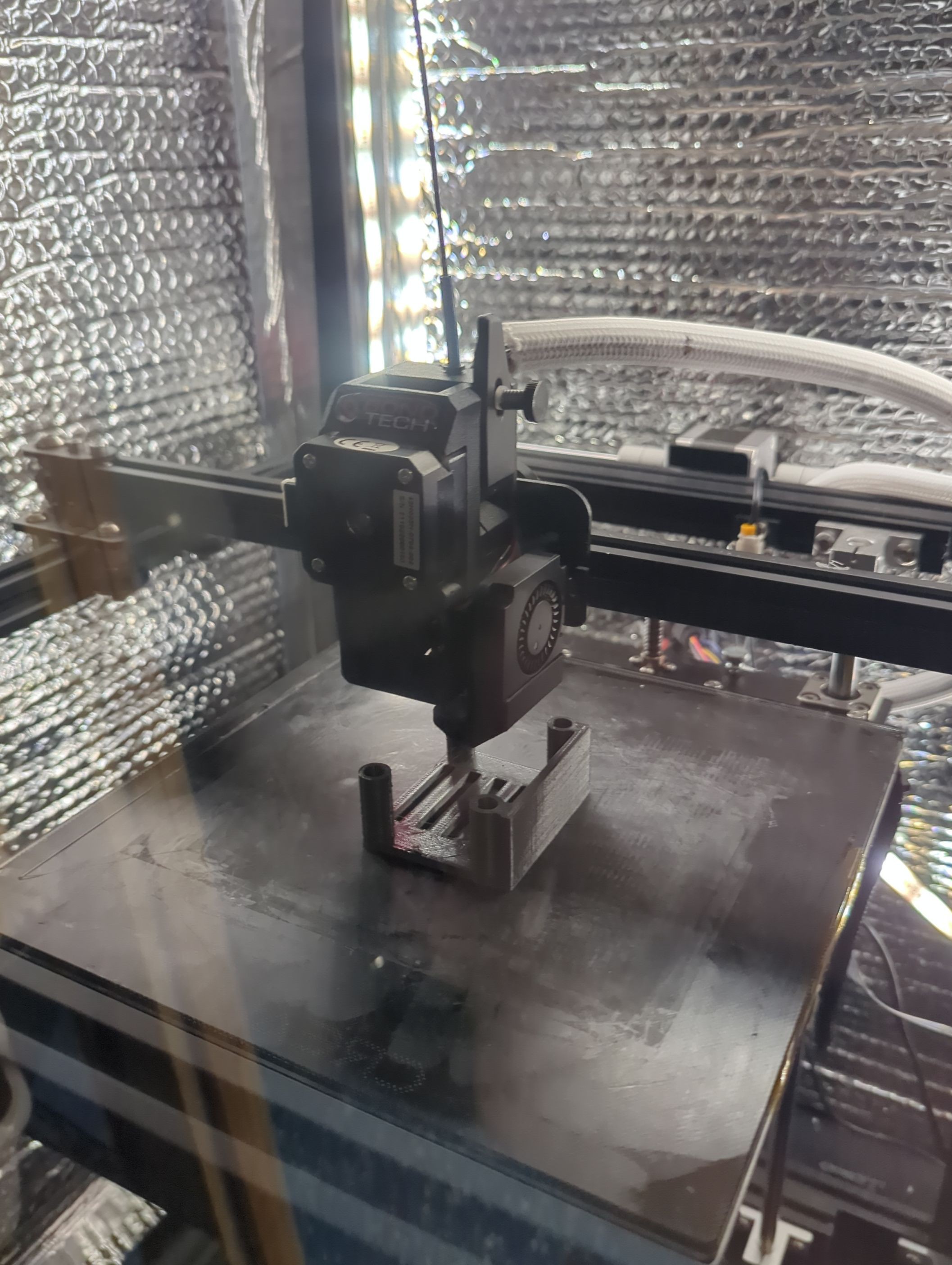
The final revision of one of the mounts came unstuck and became a giant evil glob on the hotend, and when I removed it I severed all the wires to the thermocouple and heater!
I do have my first drafts, however.
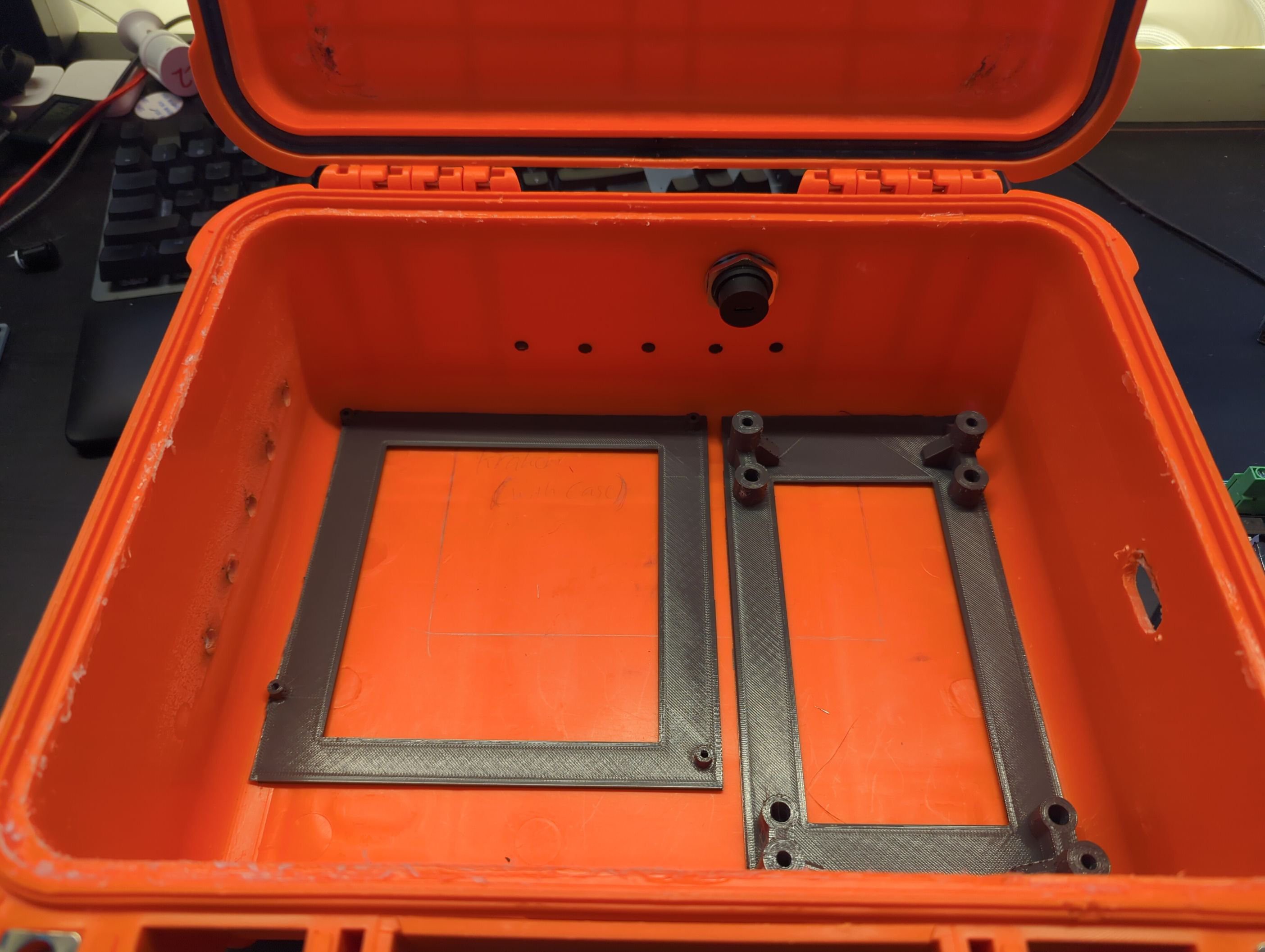
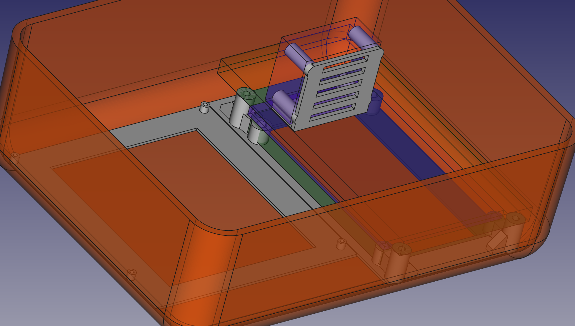
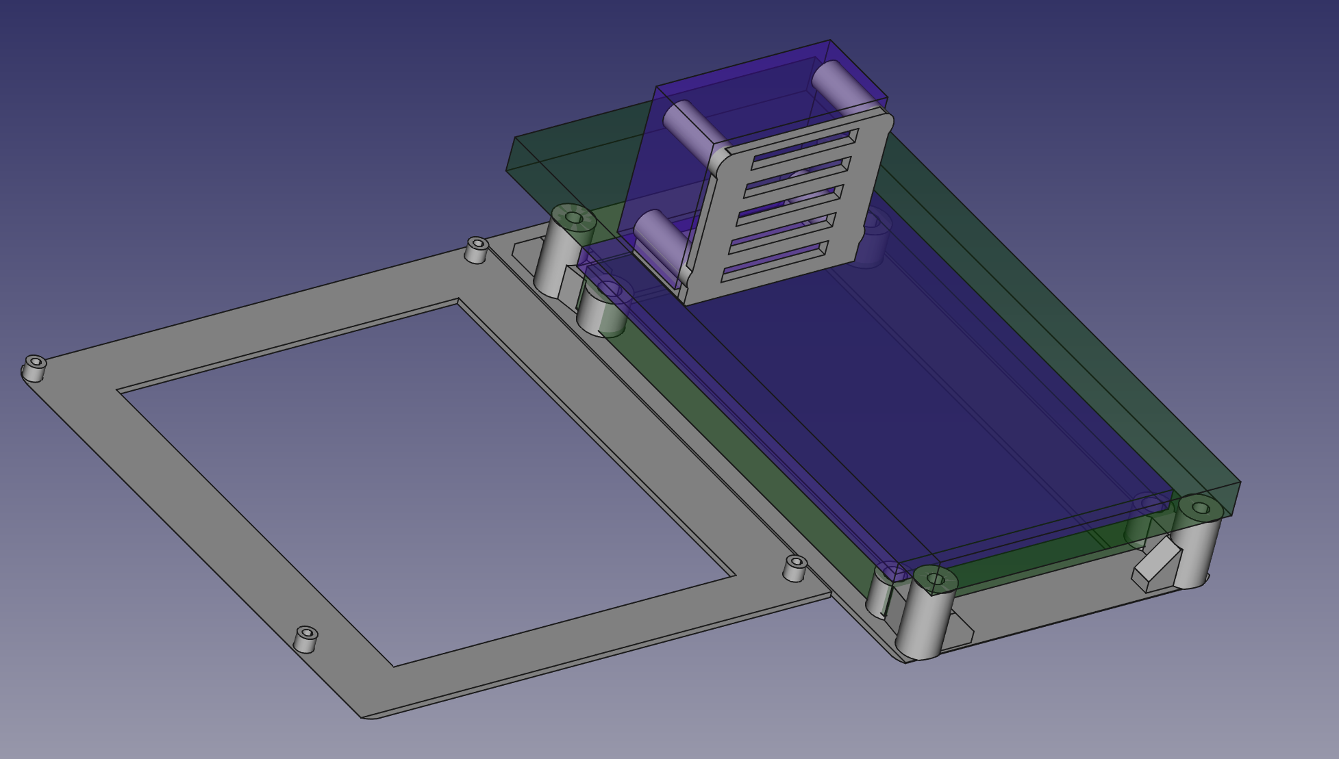
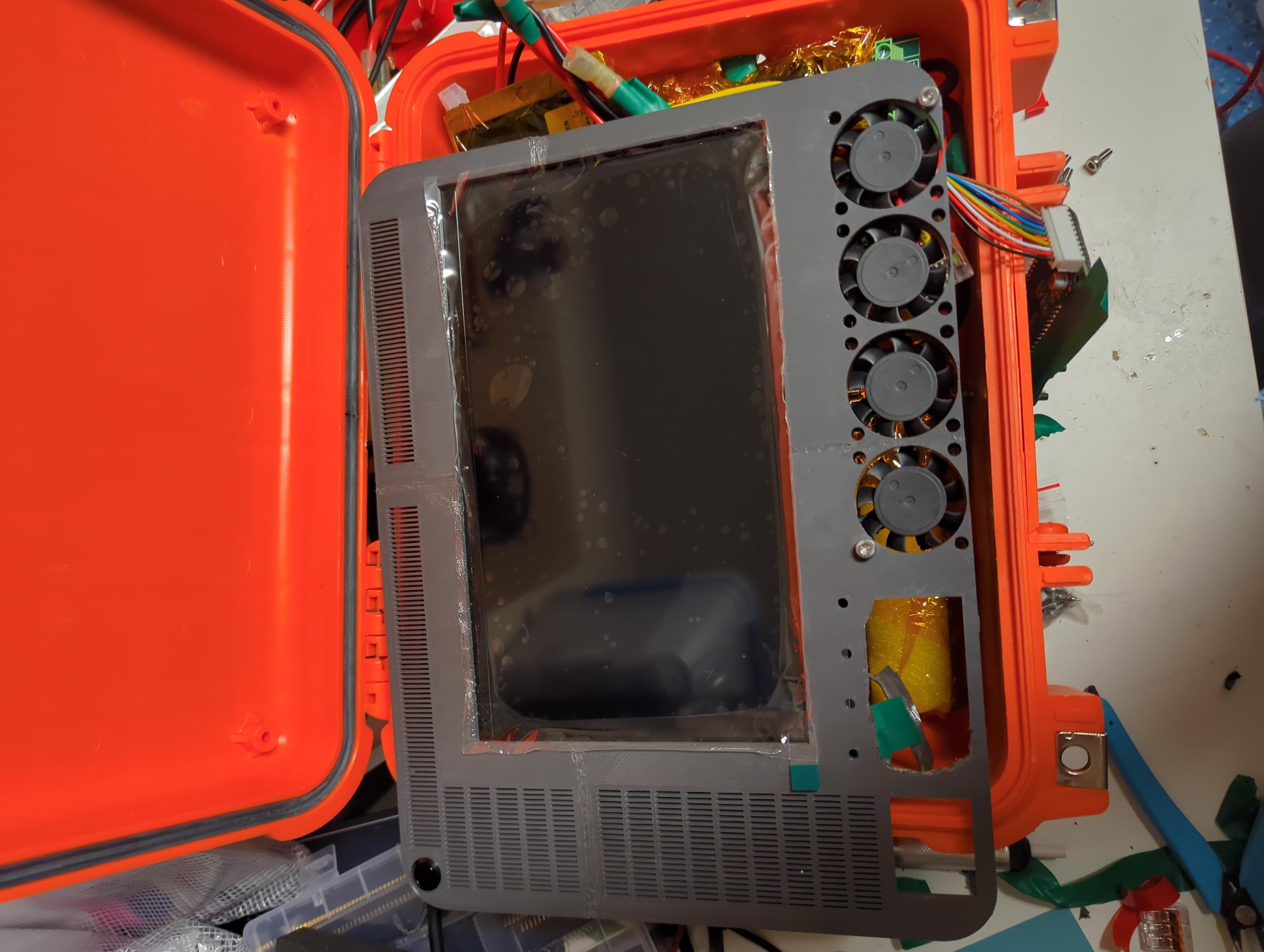
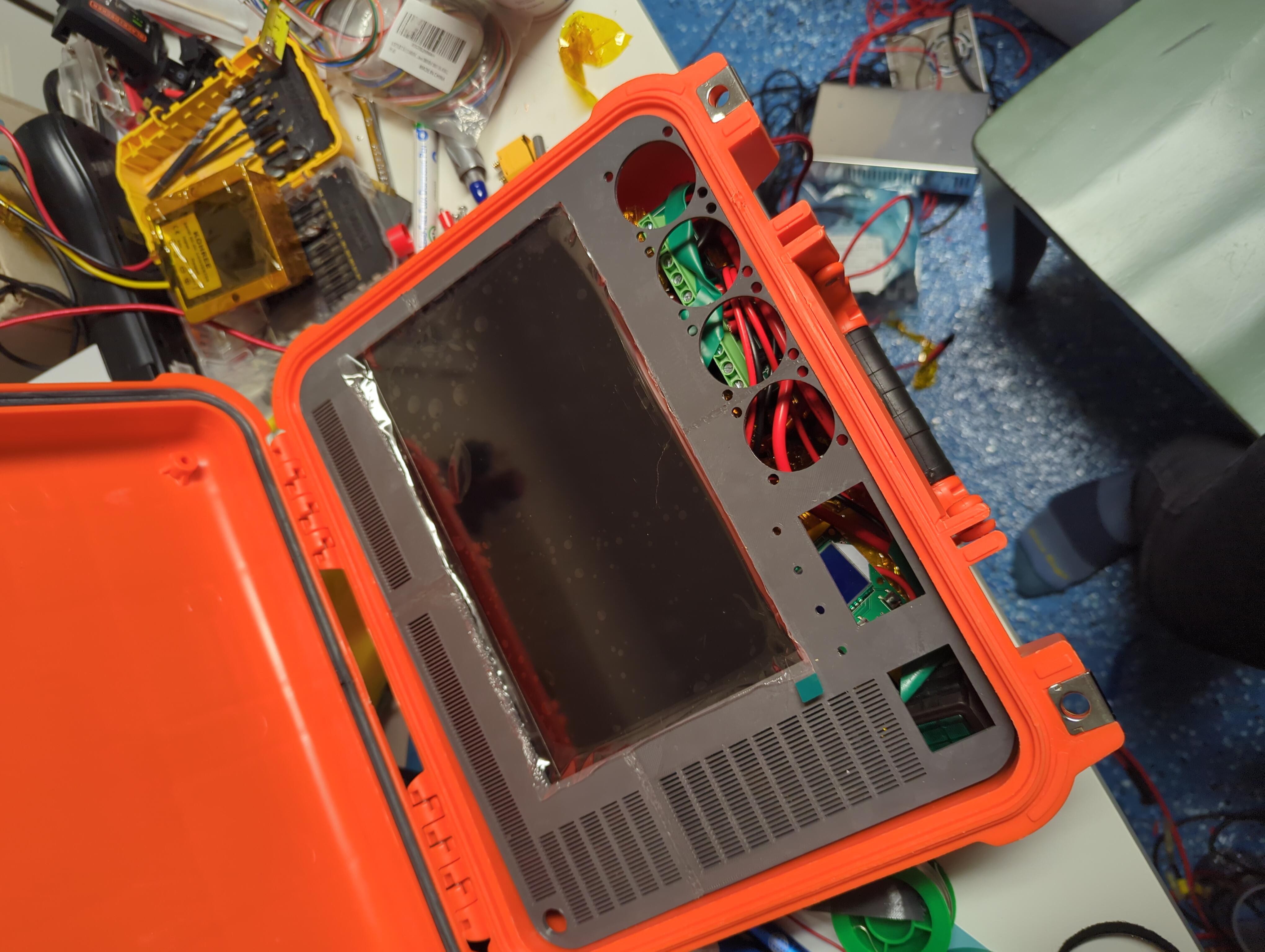
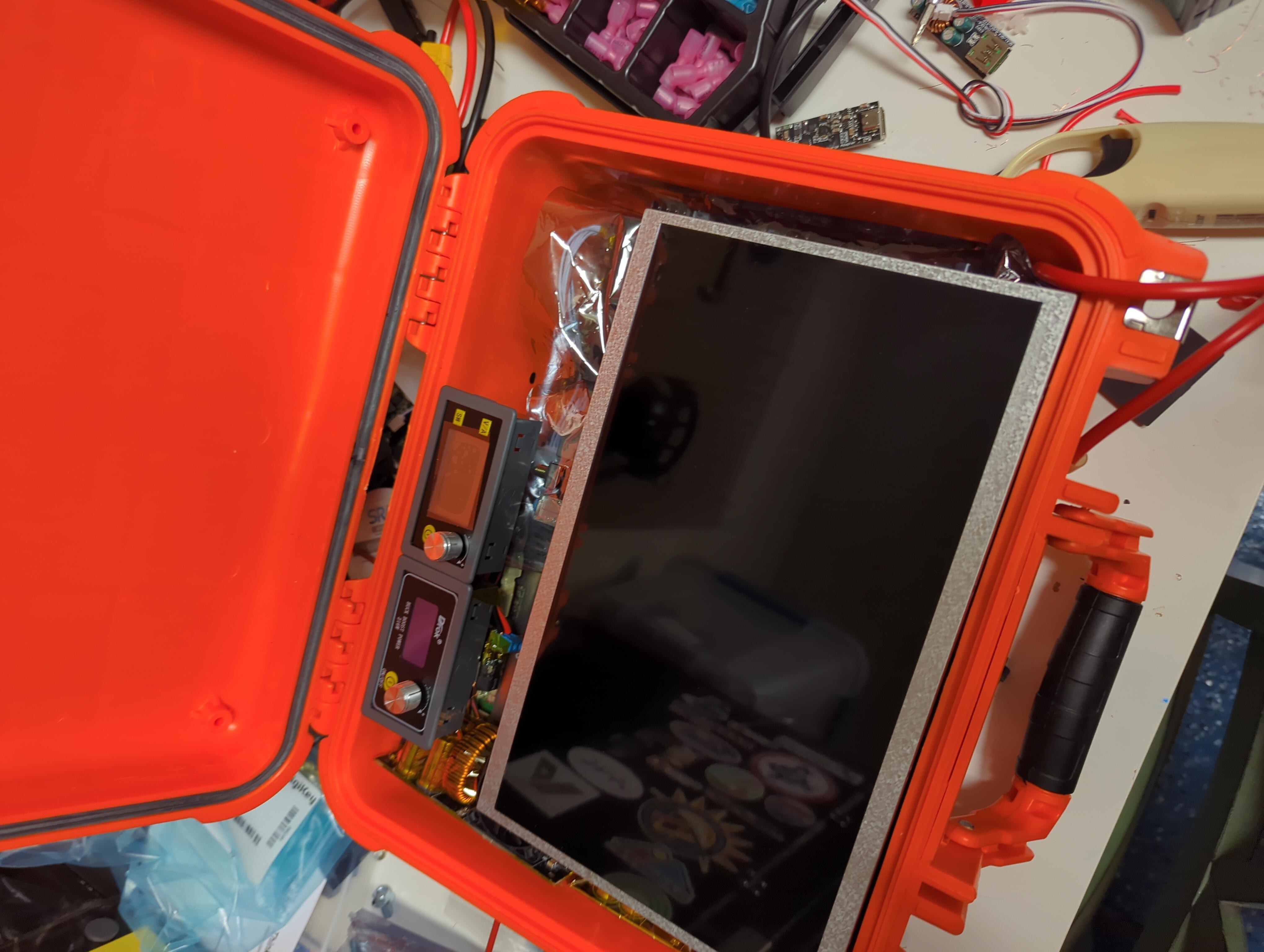
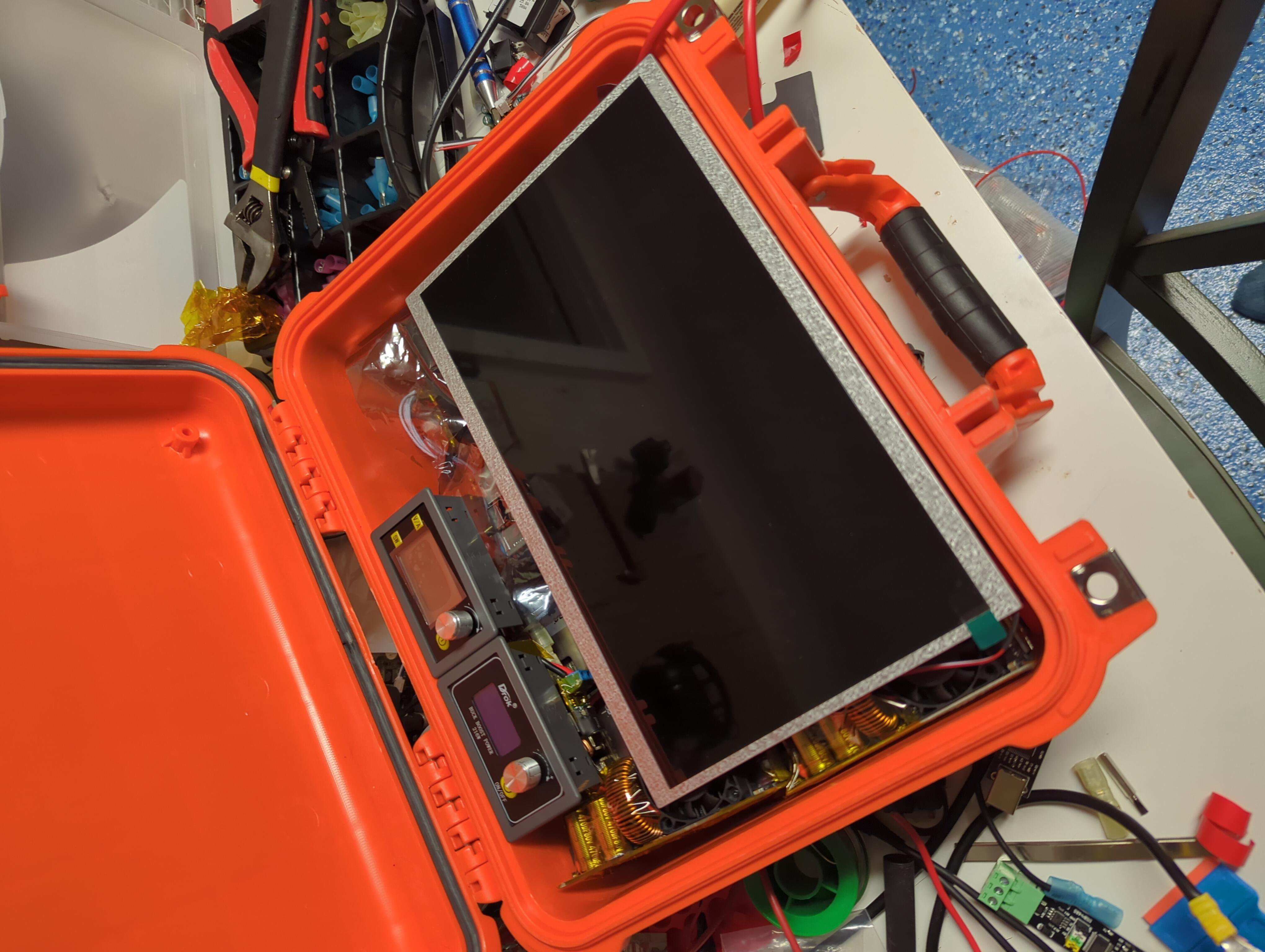
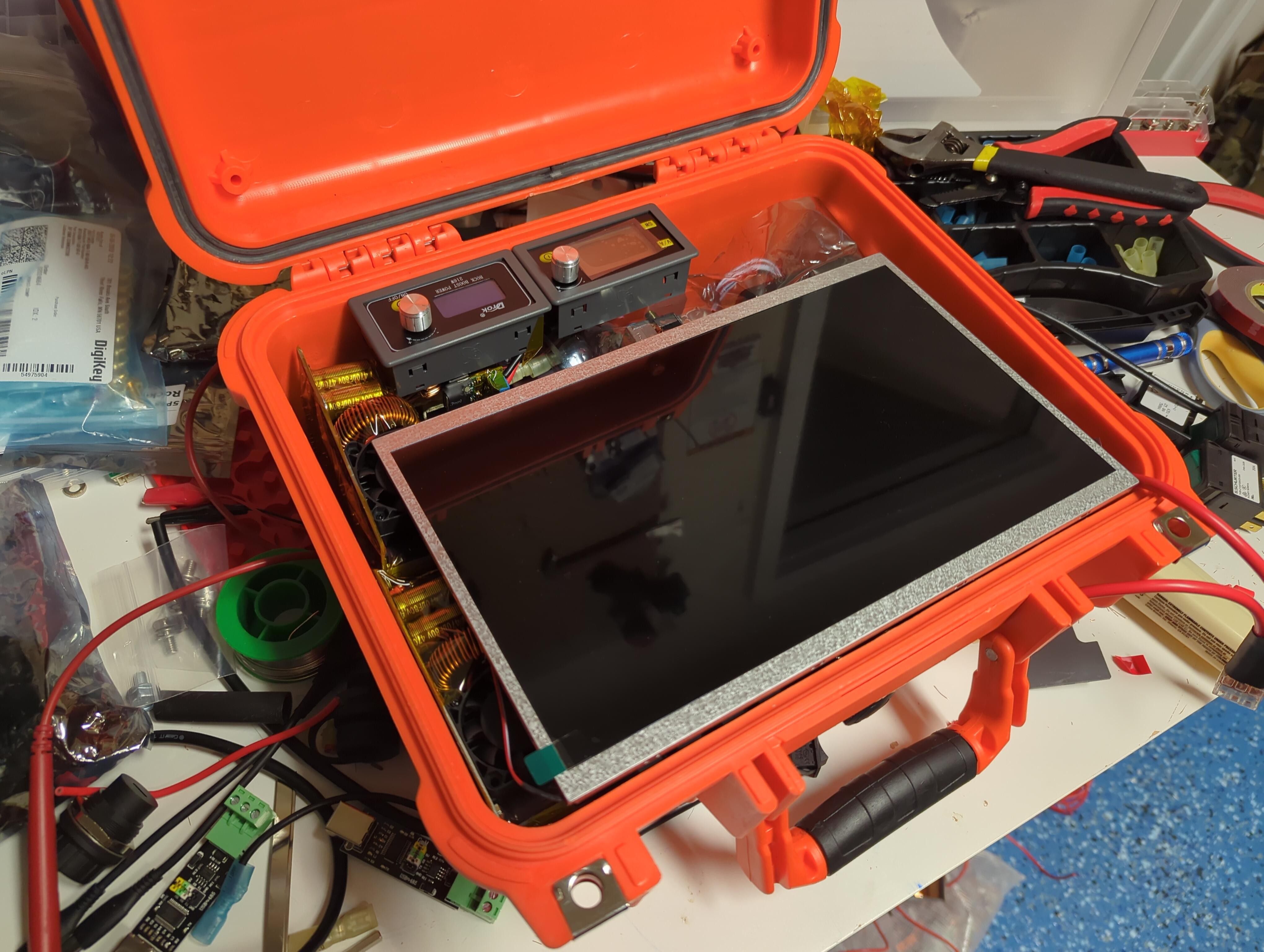
Heres a pic of the test fit with the bracket system.
TThe intention is to use adhesive to bond the printed parts to the case, then use heat set inserts and screws to mount the hardware to the brackets.
This will keep everything in place and still allow me to get in and remove or replace things if that's needed.
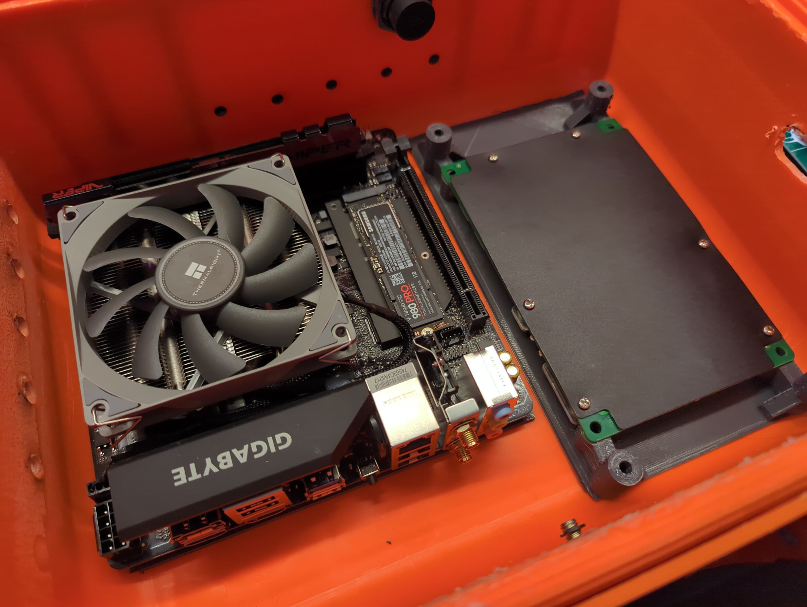
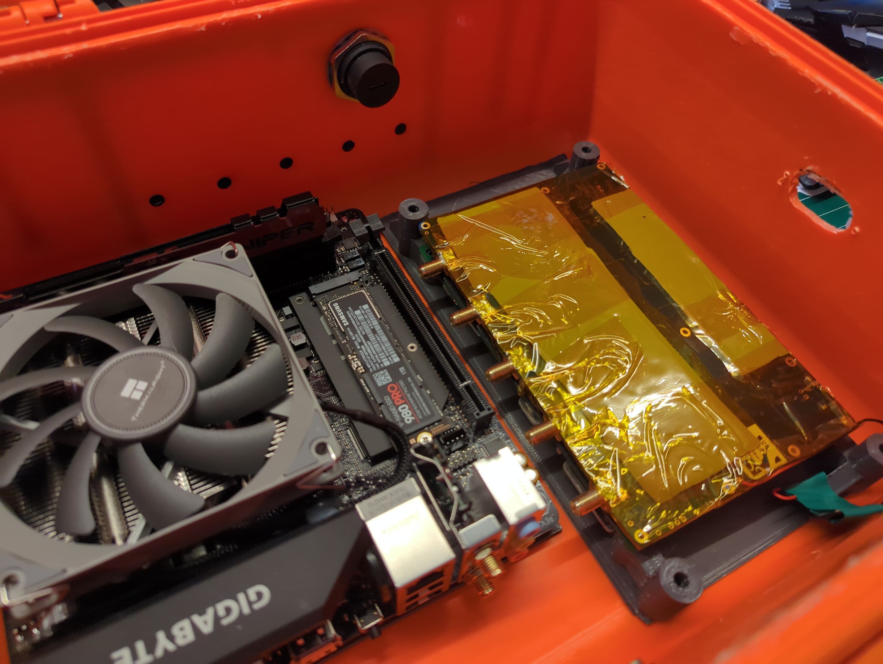
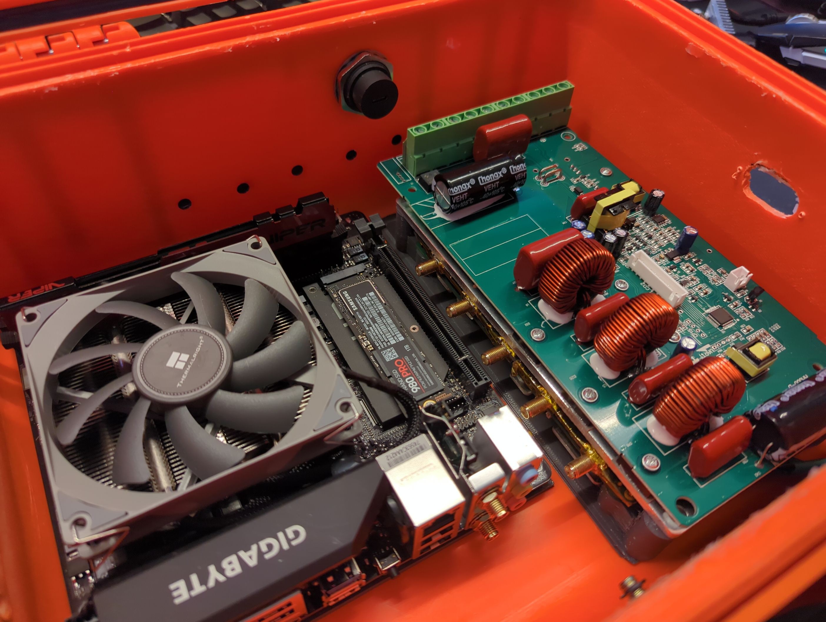
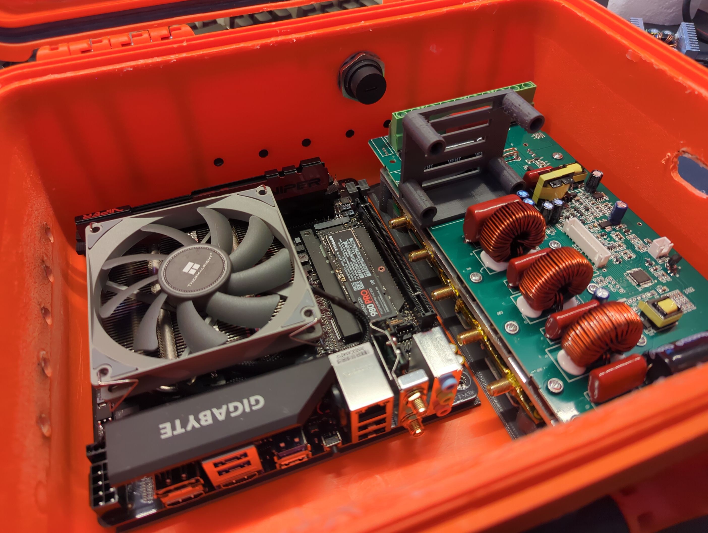
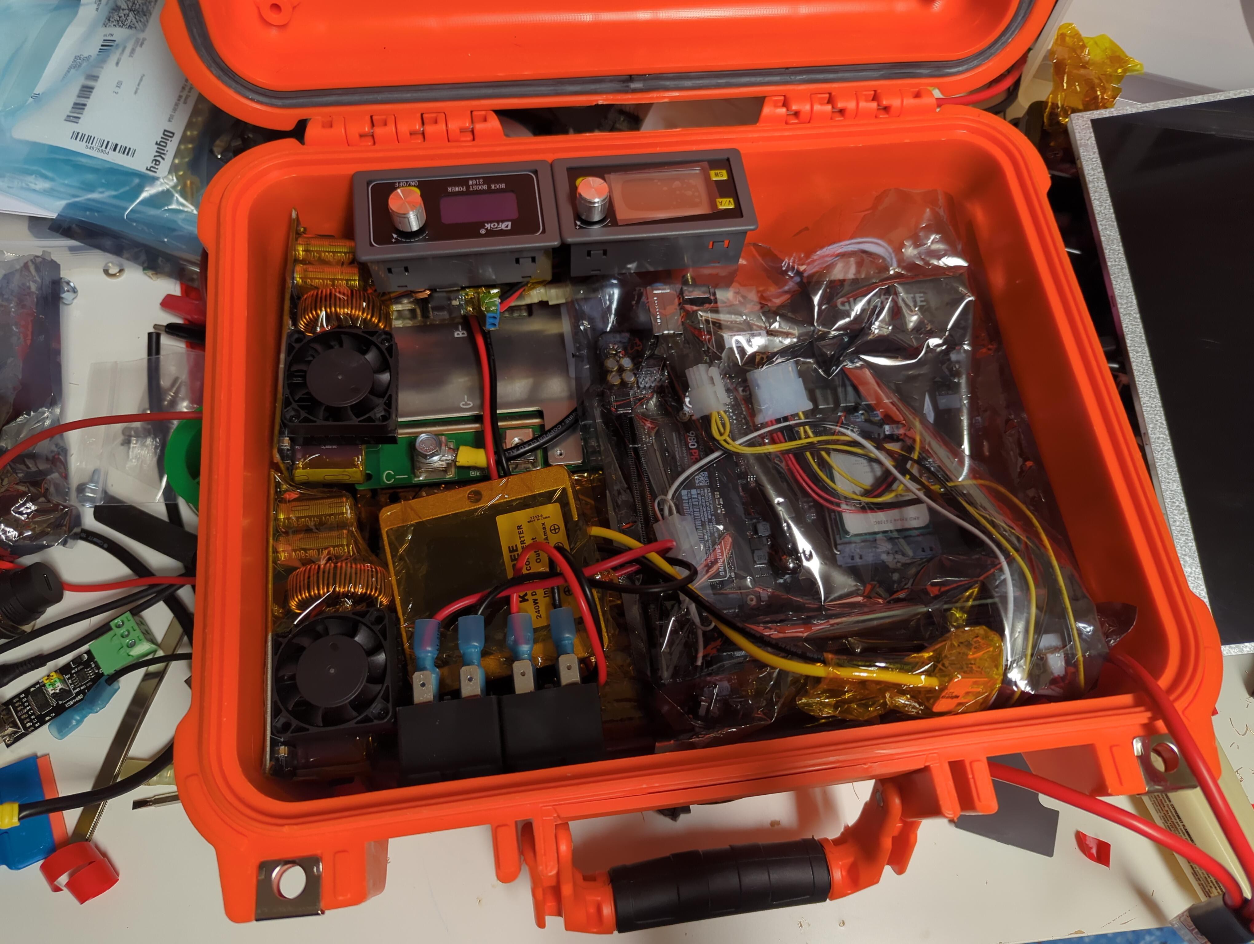
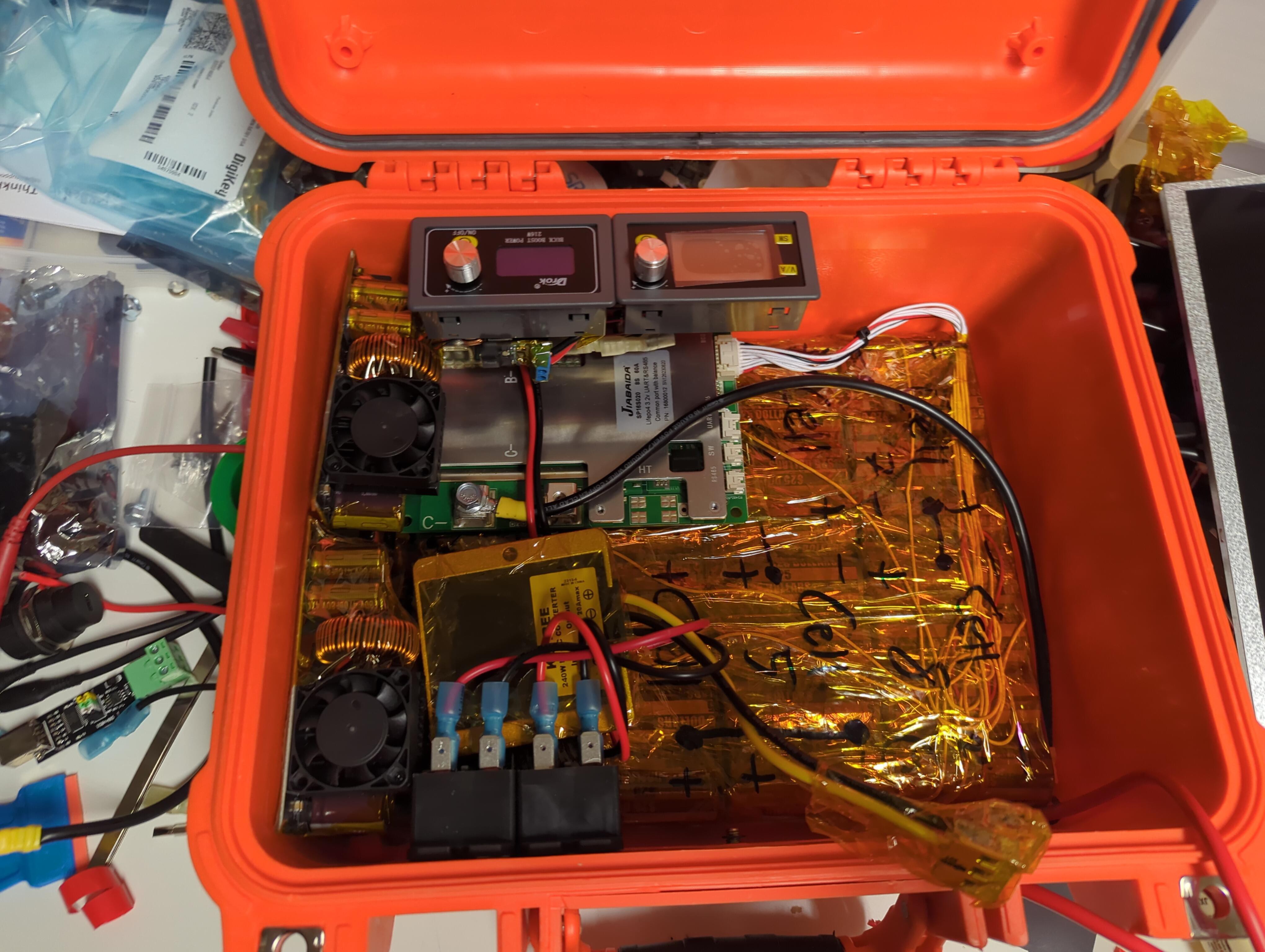
The photos show off the stack of boards one at a time so you can see the way it all fits together.
I will try to modify the existing prints by hand somehow to work.
Bare brackets The motherboard and the BMS installedKraken installed "hot" side upwards (the side with the sdr chips, in the real deal there will be a thermal pad instead of kapton tapeCharge controller, heat sink facing down24c to 12v converter not pictured as my heat insert tubes were too bulky and the heat sinks don't clear them. Bracket pictured, however, so use the power of imagination
With the reorganization idea in full swing and literally every component removed I re-measured everything and created a simple cad mockup of each board's physical volume.
I combined that, some Tetris skills, and 3 YouTube videos to calm the ADHD. The result?
I decided to mount everything directly to the case except the voltage converter, which will mount to the top of the charge controller.
Files will be uploaded after I finish printing and do a test fit to make sure I didn't mess up with the calipers.
Battery Take 3
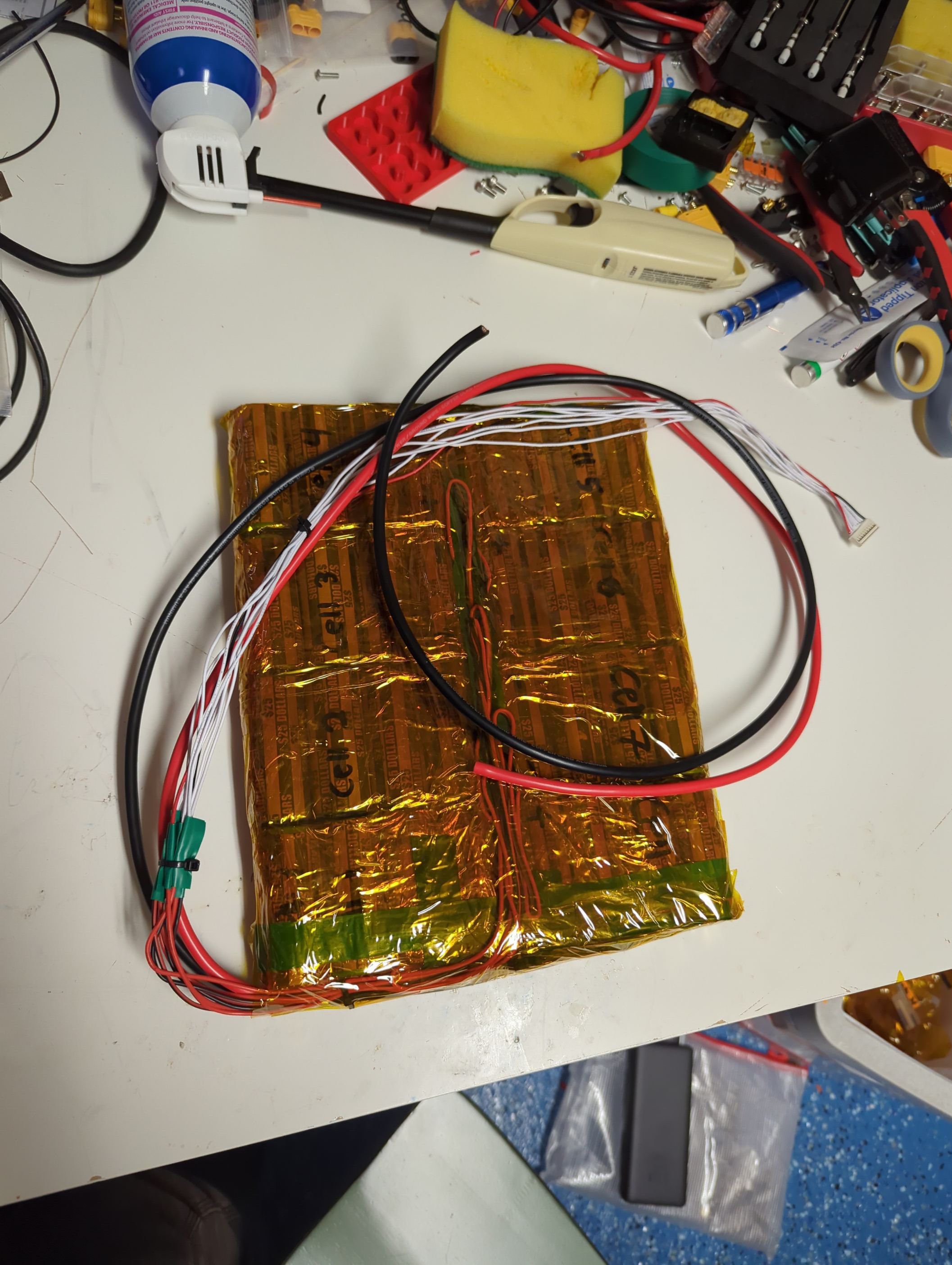
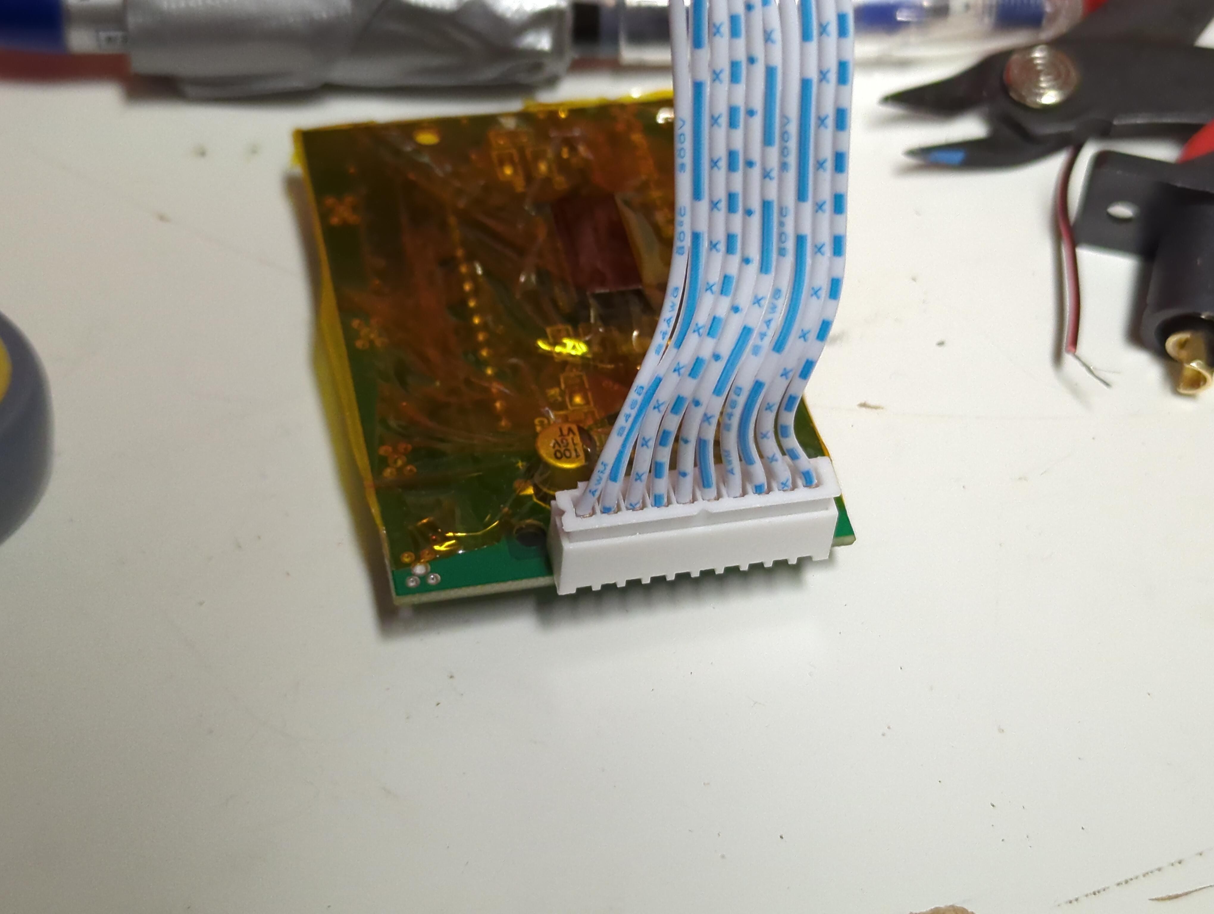
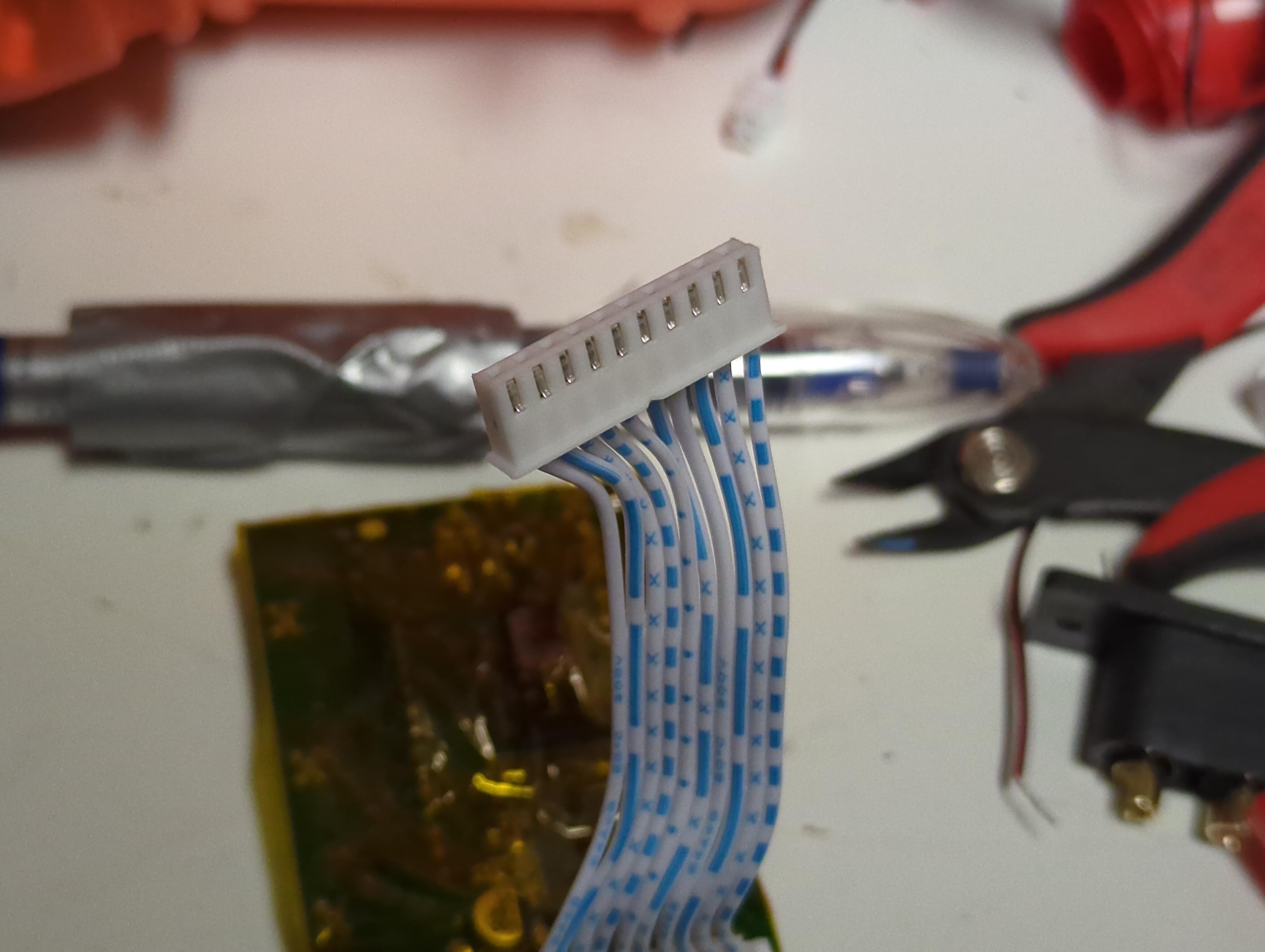
I admit I don't always think ahead far enough and I forgot that the BMS needs a wire to each cell to keep them balanced. I carefully slit open the pack casing and soldered new wire to each tab.
I closed the whole thing up and now I have an extended balancing wire harness so that the BMS can be mounted with the power cables facing the battery instead of the cable harness ports.
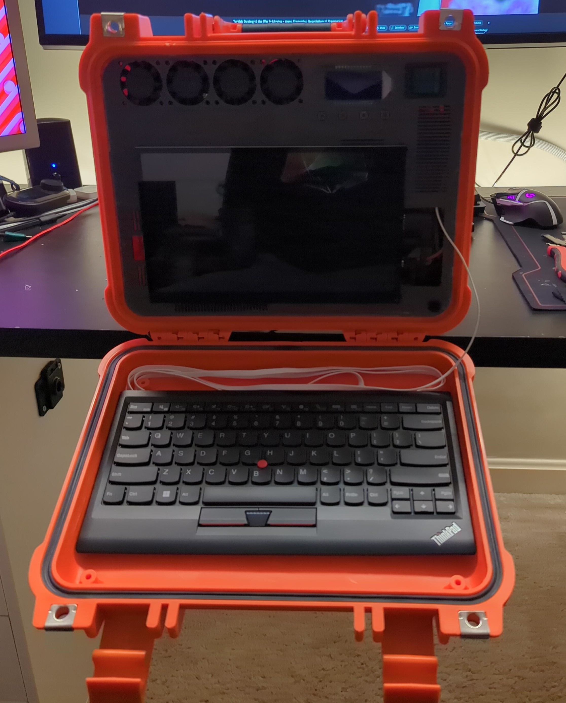
The whole case won't stand because the battery in the back is too heavy and makes the back want to lay flat, instead of lean open like a laptop.
The solution? Move the battery.
I'm moving the battery from the rear to the small front side flap of the case, aka the lid.
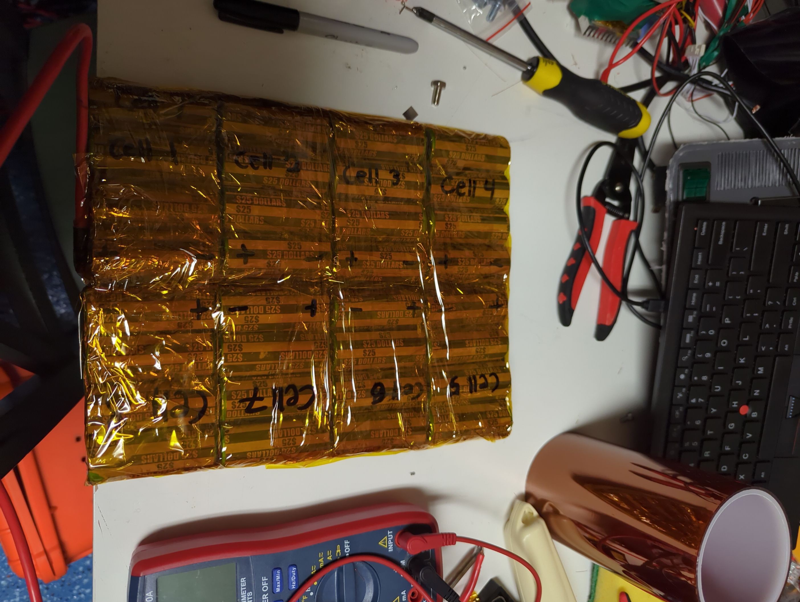
I decided to take the opportunity to tear the battery down and re-pack it.
Each "cell" is composed of 4 sony cells in parallel. Each Sony cell is wrapped in a 50¢ coin wrapper to prevent damage to the wrap. Each set of 4 is welded with nickel strip with excesses on one side, then wrapped in laptop tape.
The excess tabs are then welded together, folded over, and taped. This is done one after another to form the final battery pack.
The final pack is then wrapped in tape to provide just a little more structure.
Stranded copper wire in silicone jacket is soldered to the excess tabs that make up the positive and negative leads of the pack.
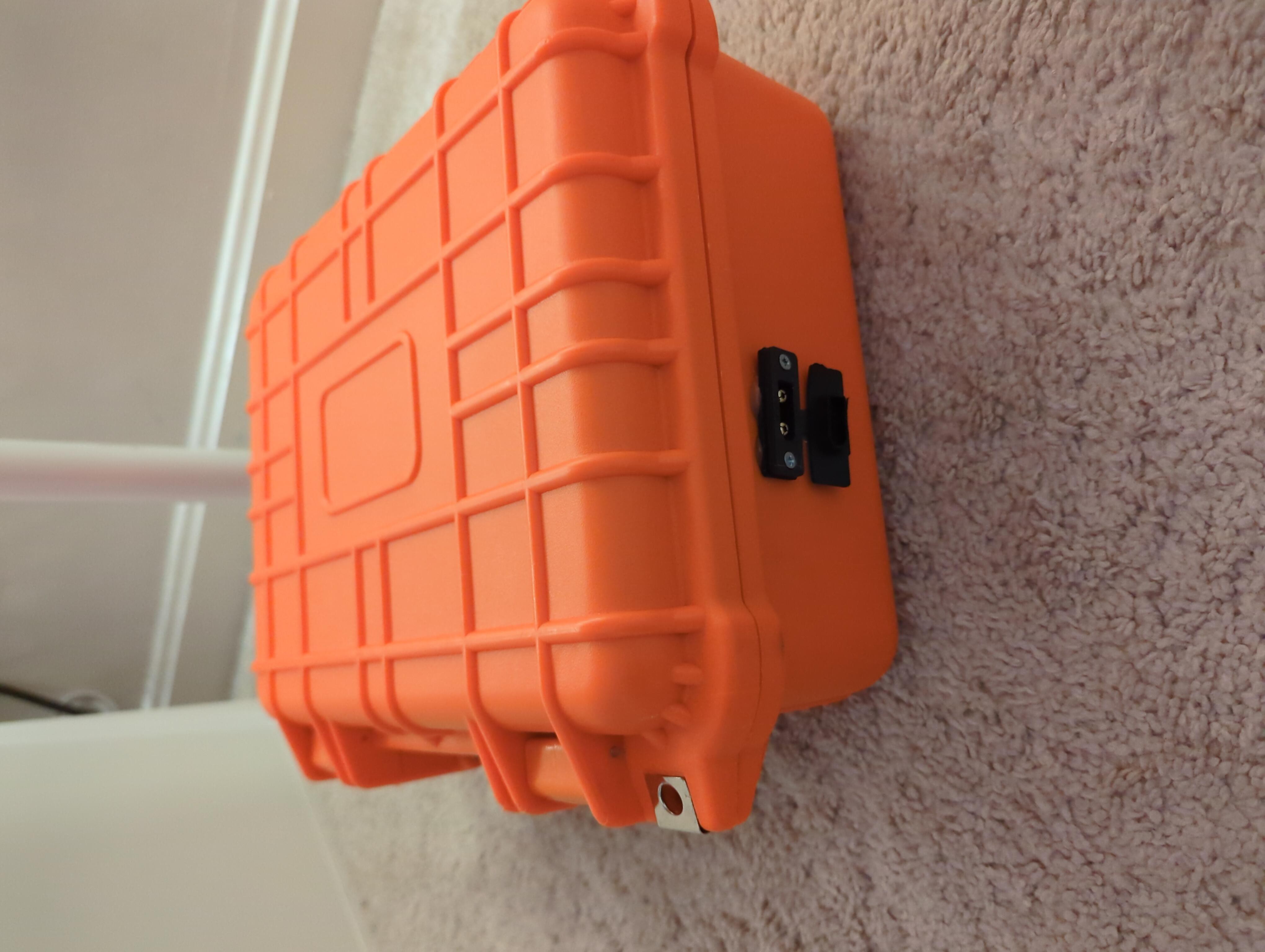
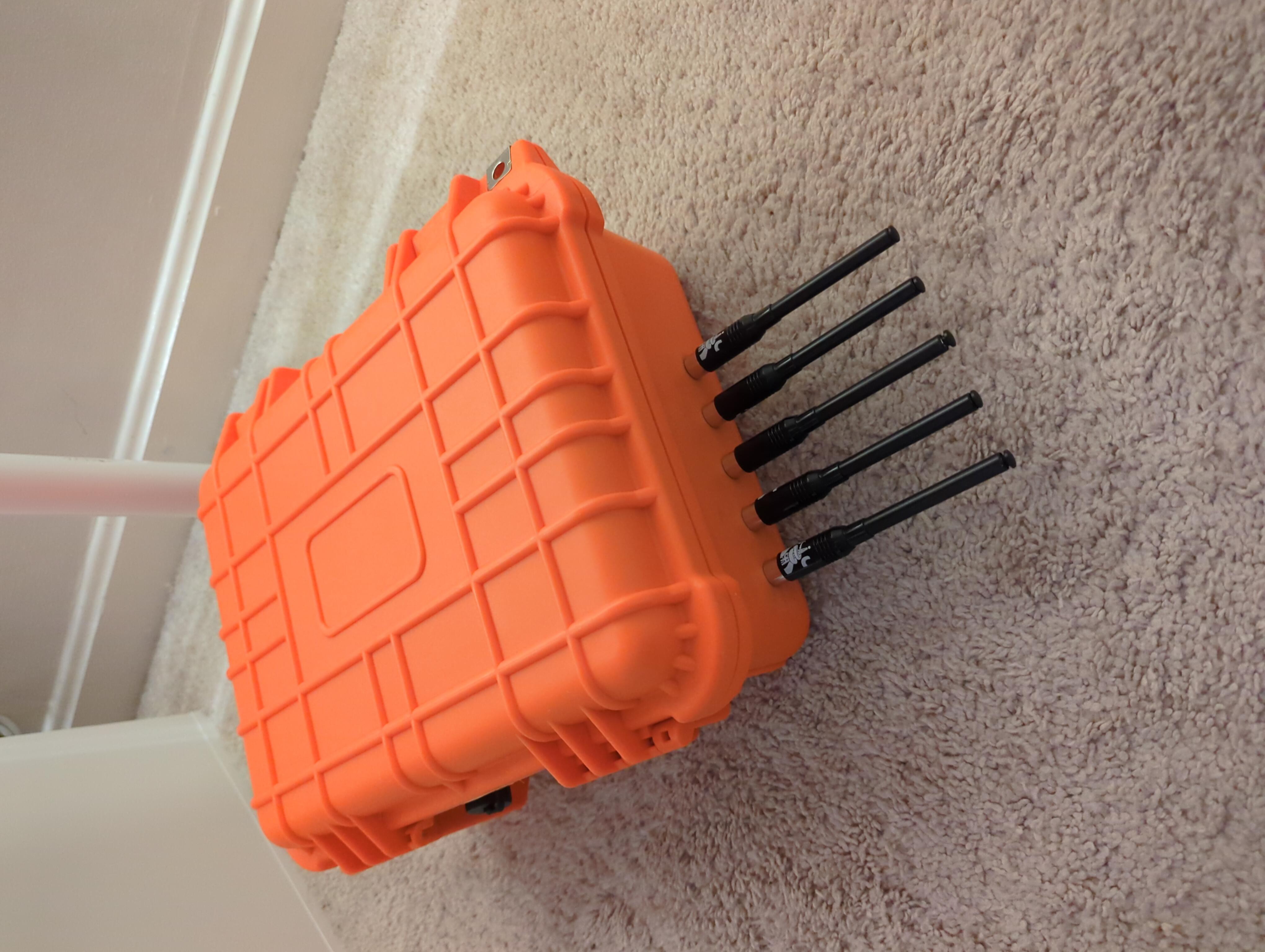
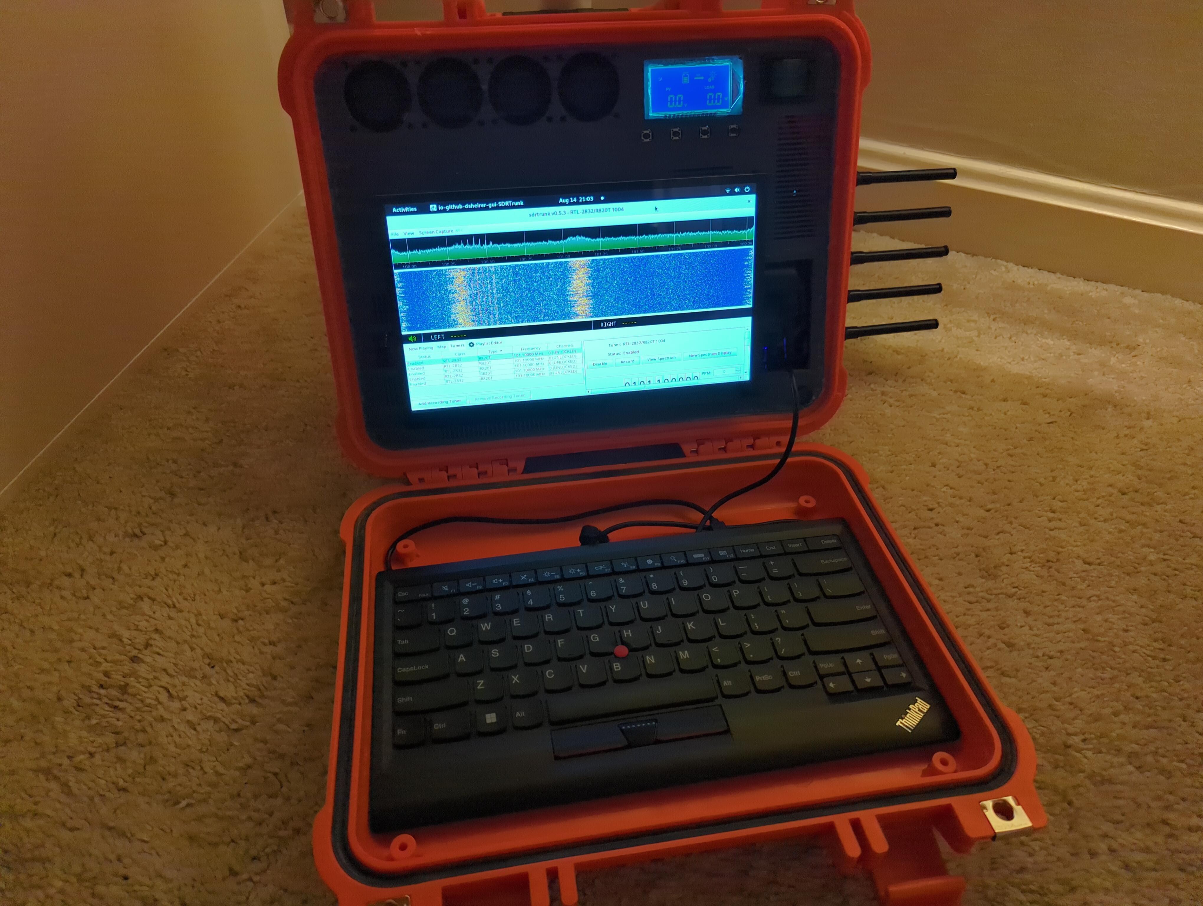
I don't have a fancy photography setup, so the closest I have is the white carpet under my white desk. So here's the worst action shots you've ever seen.
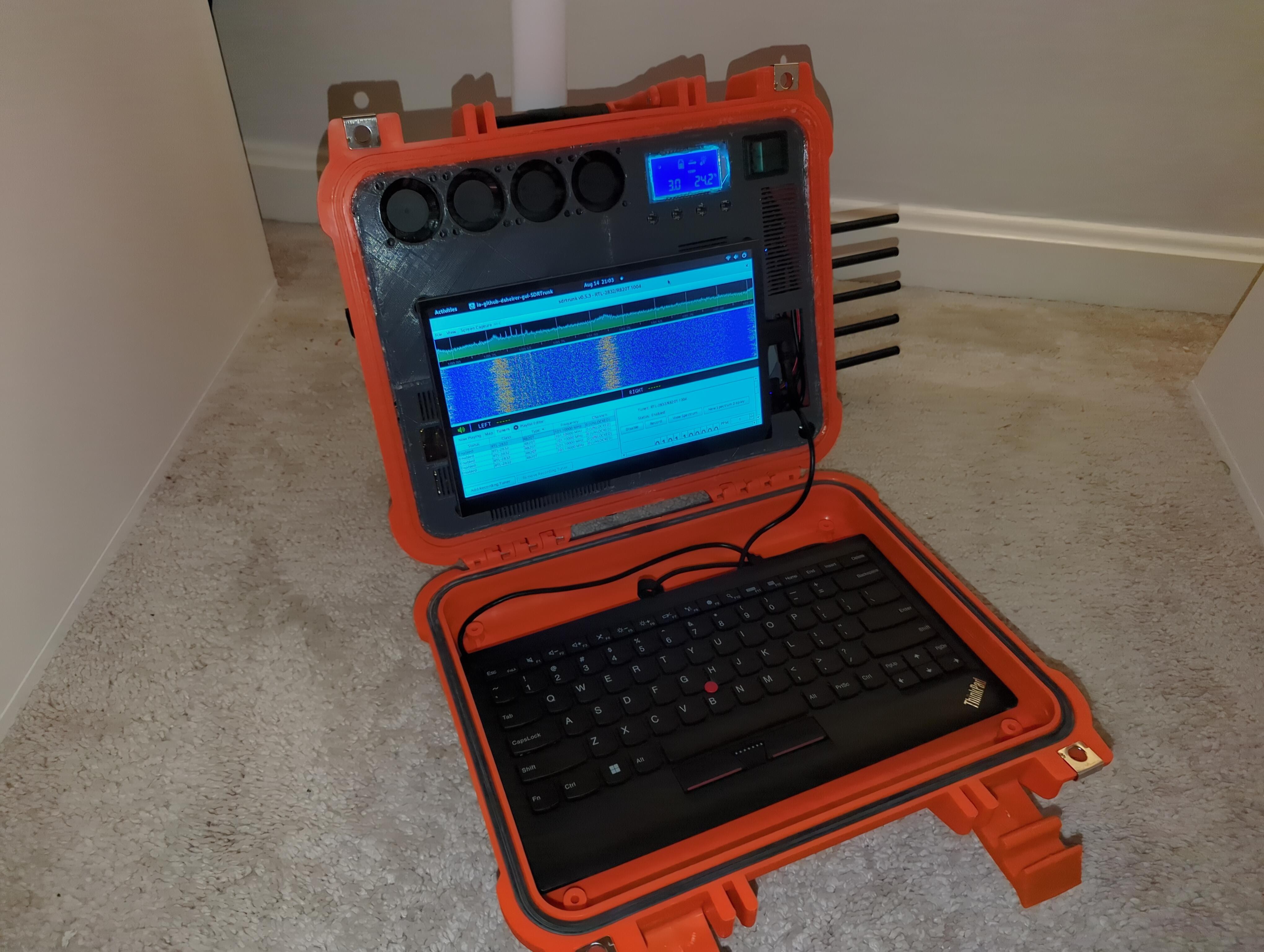
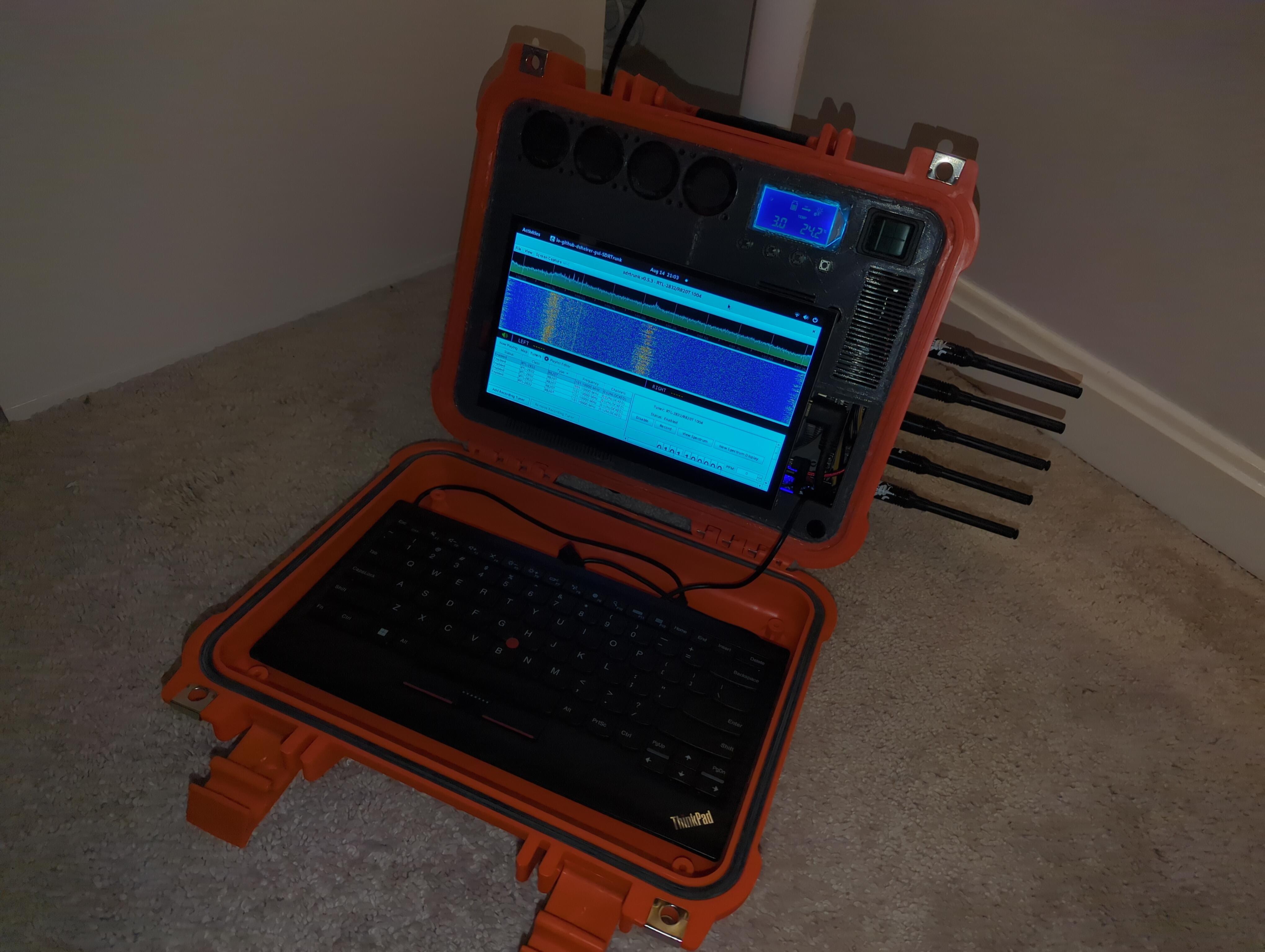
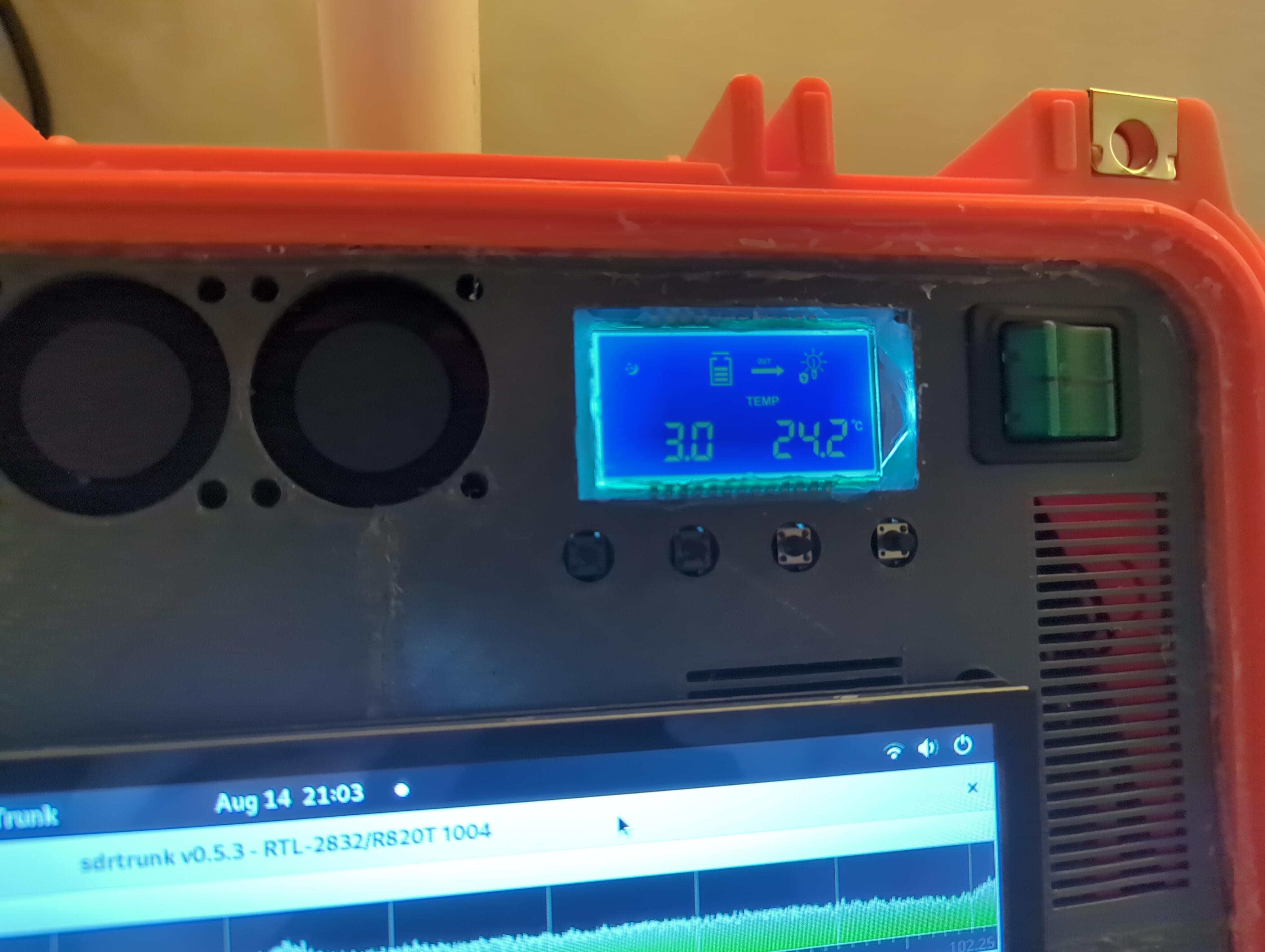
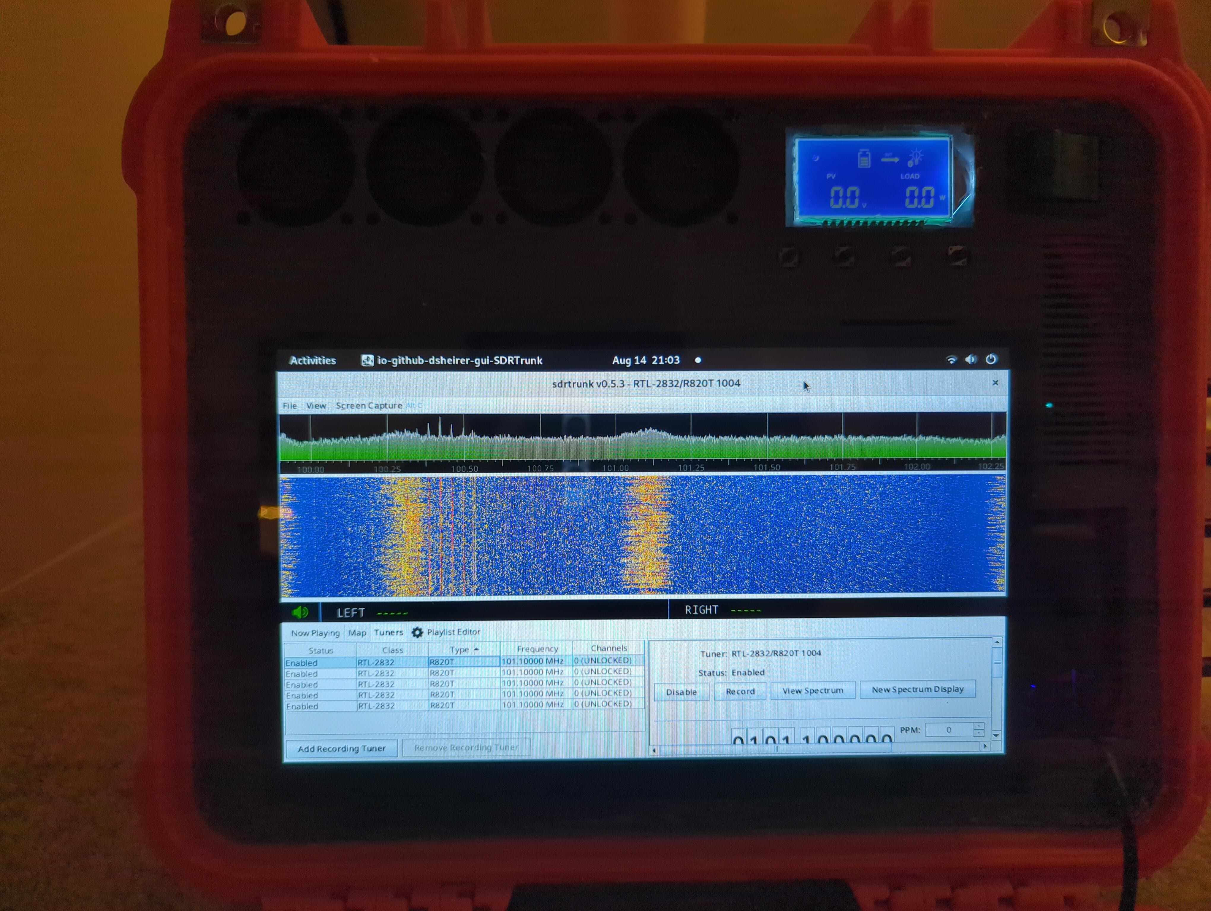
Since the old screen was not cooperating, I went with what I could find on amazon with fast shipping, to make it to the deadline of the contest.
Also because I really wanted to see it work.
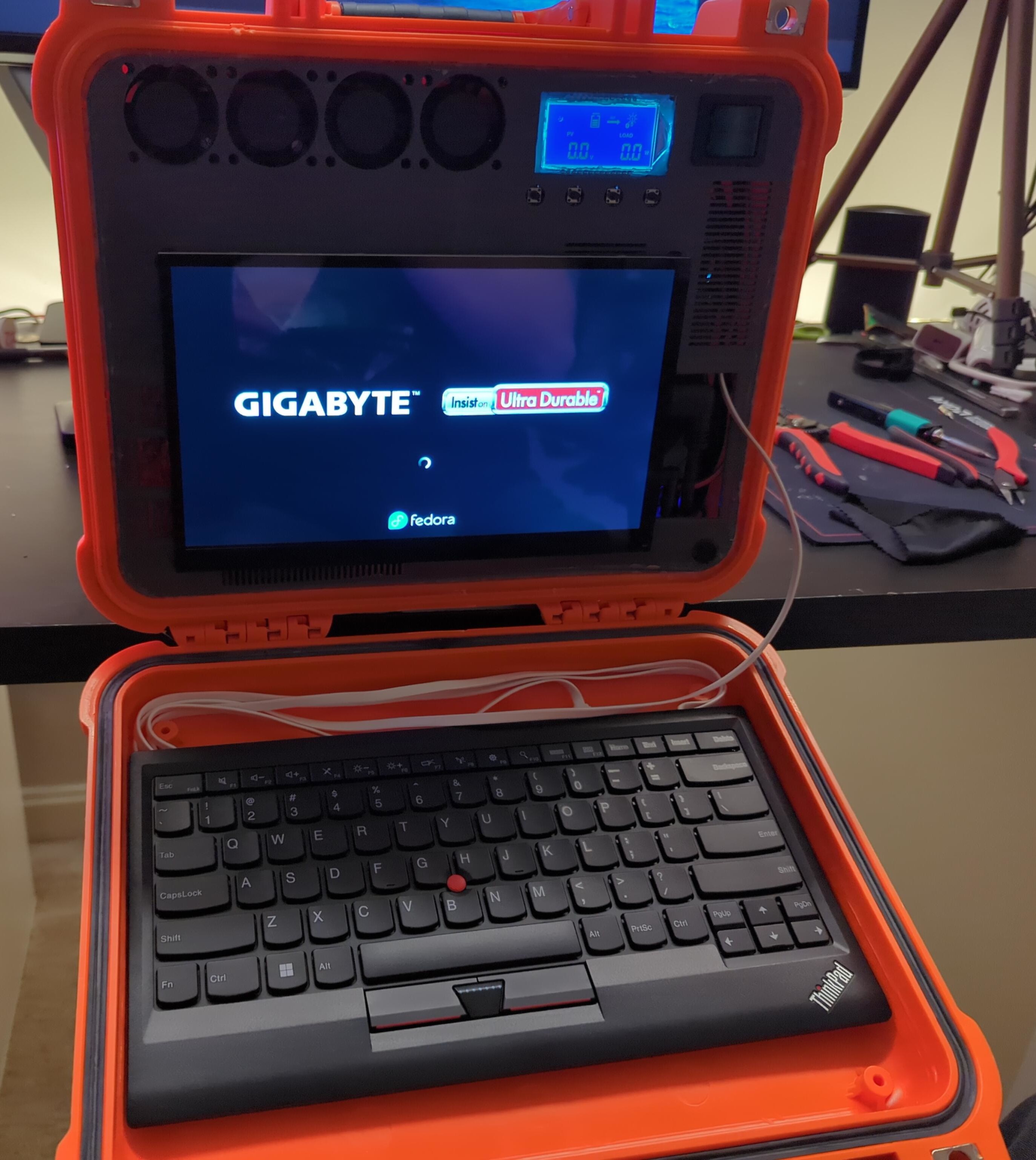
Unfortunately I spent 2 days trying to figure out why my system would boot up, show the BIOS logo and NOTHING ELSE. I was convinced that I had really messed something up, that I had shorted the board somewhere.
After talking to some friends on discord, I decided to try a new pico PSU, just in case, which turned out to be... not needed at all. Anyone need one?
It turns out the board shipped with firmware that couldn't handle the CPU, so one flash later and we're in business.
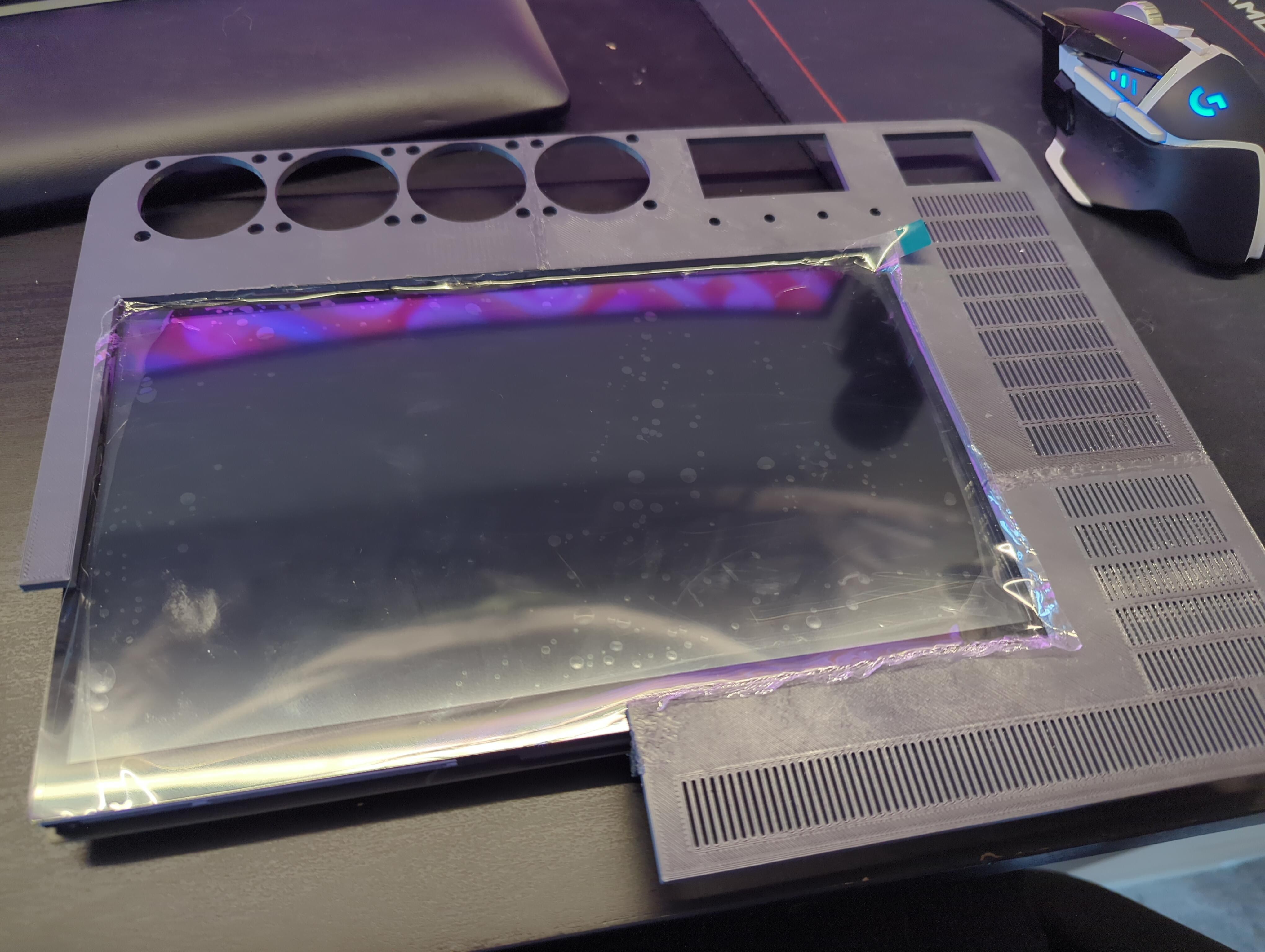
I reprinted the faceplate, pretty much a total redesign for the screen portion with the rest left untouched. there's fewer vents in this version, but more holes, so I think it evens out. In any case the idea is that the intake fans feed the CPU cooler which acts as the output fan.
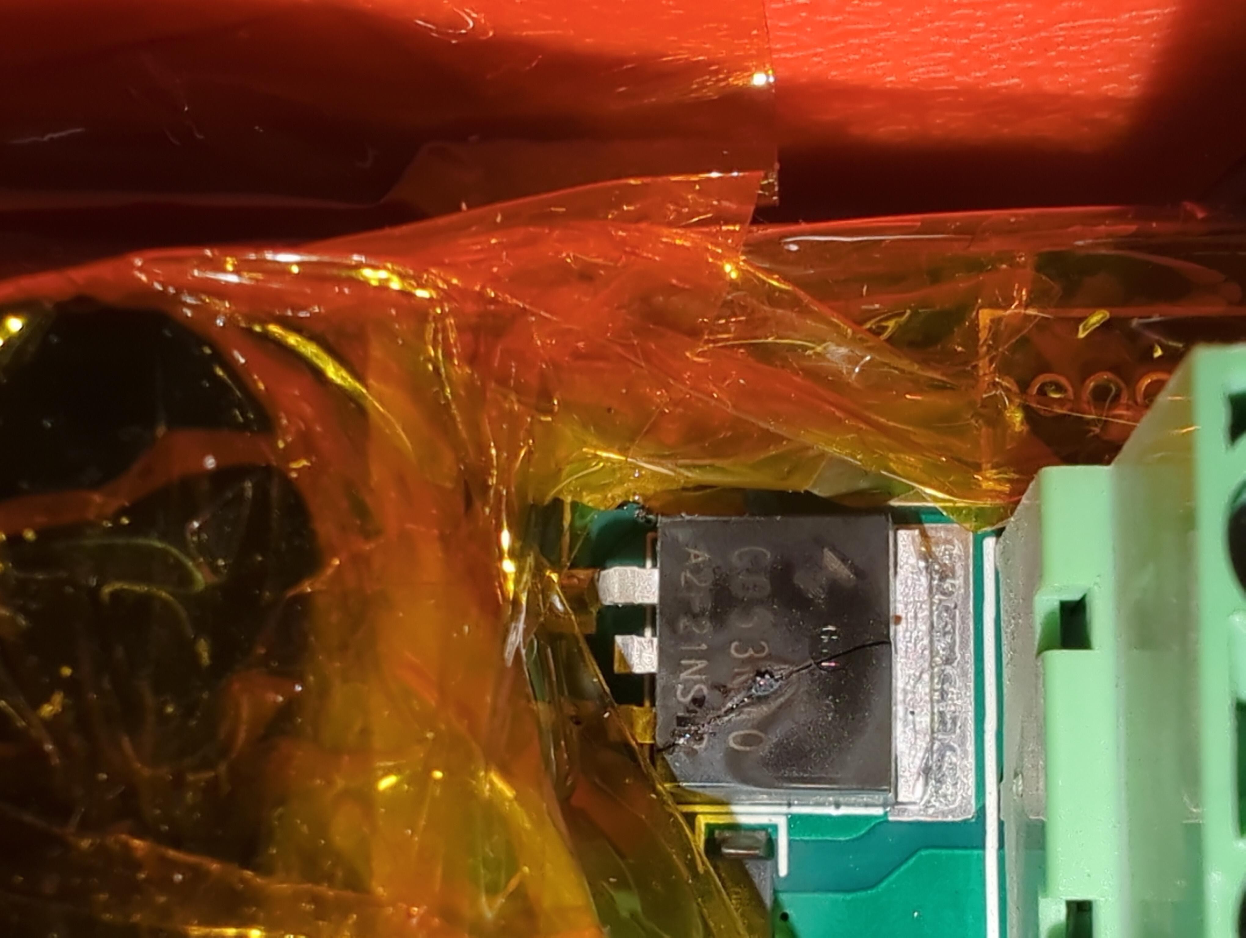
I found out the hard way that the PowMr was not putting out a small regulated DC voltage like most MPPT controllers claim to, and the output was in fact the whole 25V of the battery pack.
The cable for the screen for it is also wayyyy to short to make it out from behind my screen
At this stage I believed I needed to isolate the load from the input charge voltage.
I used three different voltage controllers, one for normal battery charging, one for the PC, and an entirely separate one for charging the battery over USB.
 Andrea