We didn't expect this, but our humble GitHub was discovered by PCBWay, and they kindly offered to sponsor several boards for our project. Since we already had some sketch of our pedal enclosure in 3D, we took all our previous schematics and developments with the stacking layout and, within a few weeks, designed new boards for this enclosure. It was a fast-paced effort, but it served as a good stress test for our team, inspiring us to pay more attention to our publications and the project as a whole.
---------- more ----------
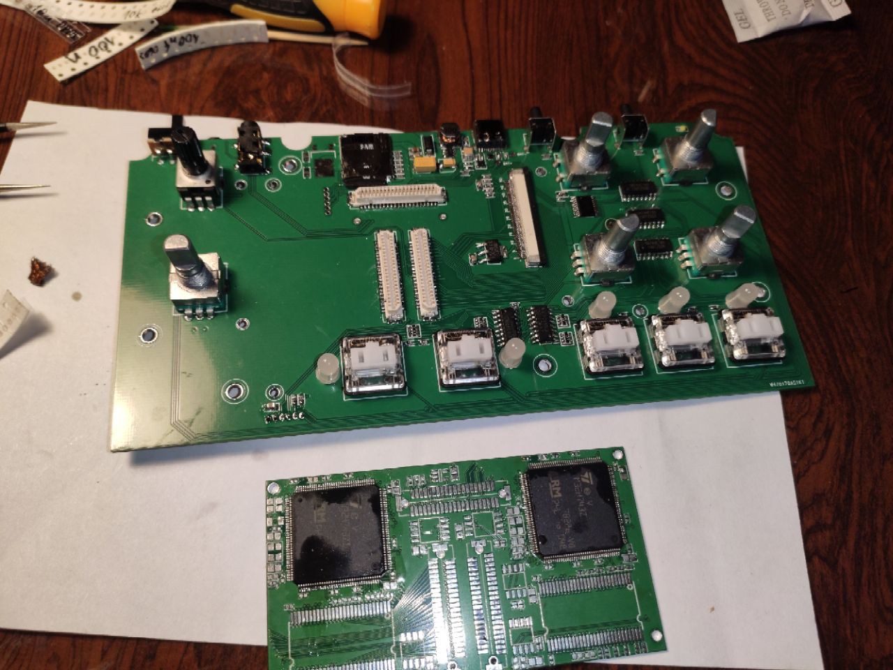
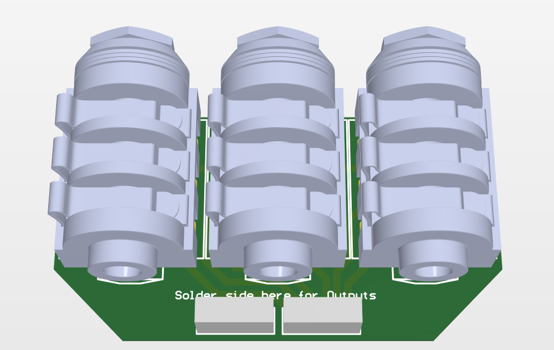
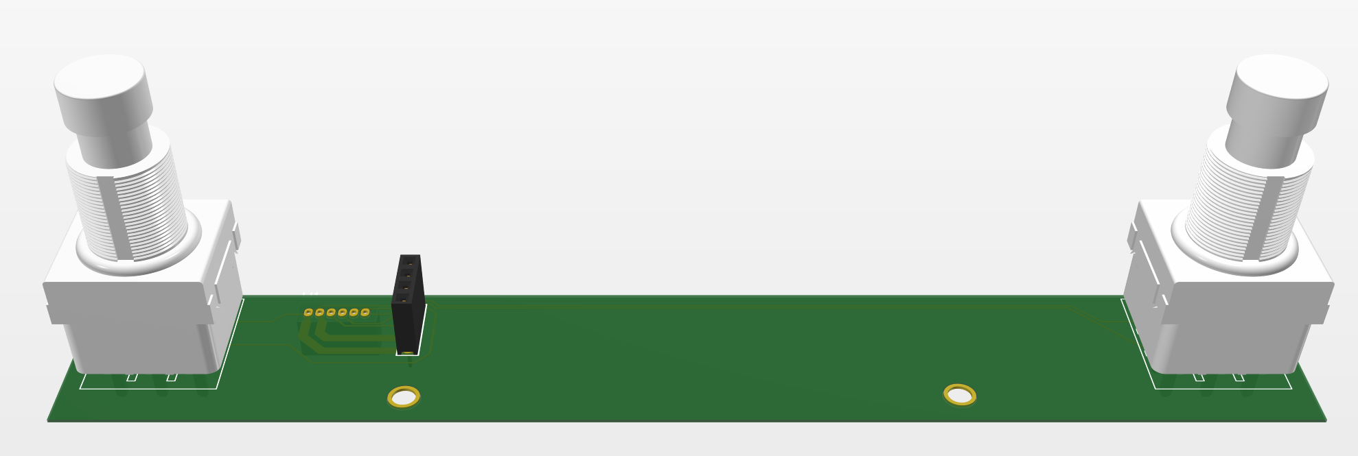
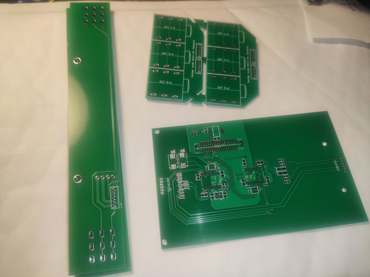
— We received the MCU boards and Main boards from PCBWay, as well as the Codec, Audio Connectors, and FootSW boards from our local PCB manufacturer.
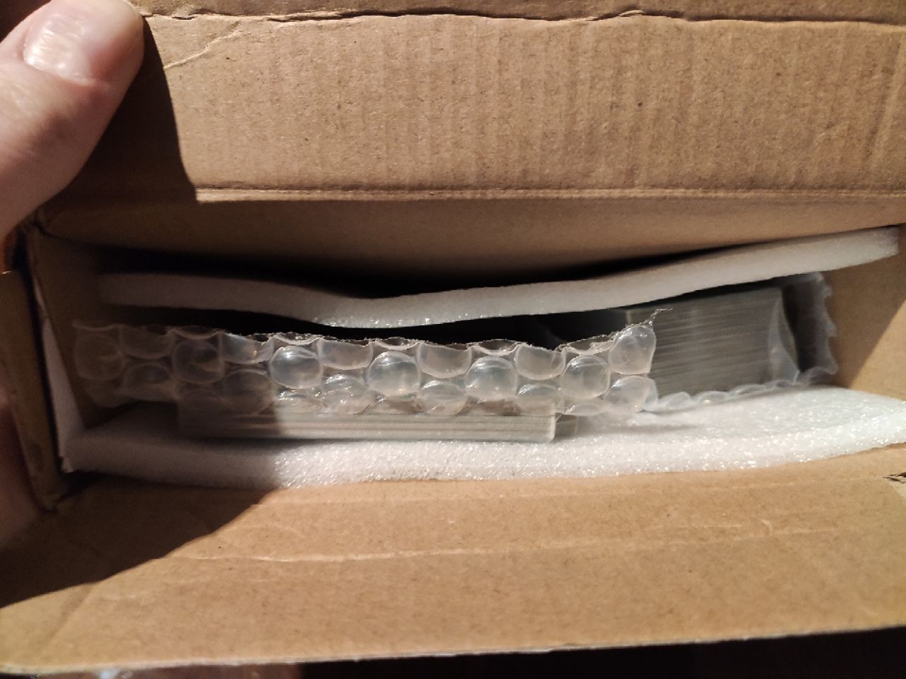
Packaging
The package from PCBWay is kind of most PCB manufacturers standard, but nice for the price - branded box, some foam inside, and most importantly, all PCBs are vacuum-sealed in bubble-wrap, which prevents them from flying around and rubbing against each other.
The package from our local PCB manufacturer (we use express build and delivery option which gives us one and a half week from order to solder) for small-scale PCBs looks like a branded A4 format envelope, covered with bubble-wrap inside.
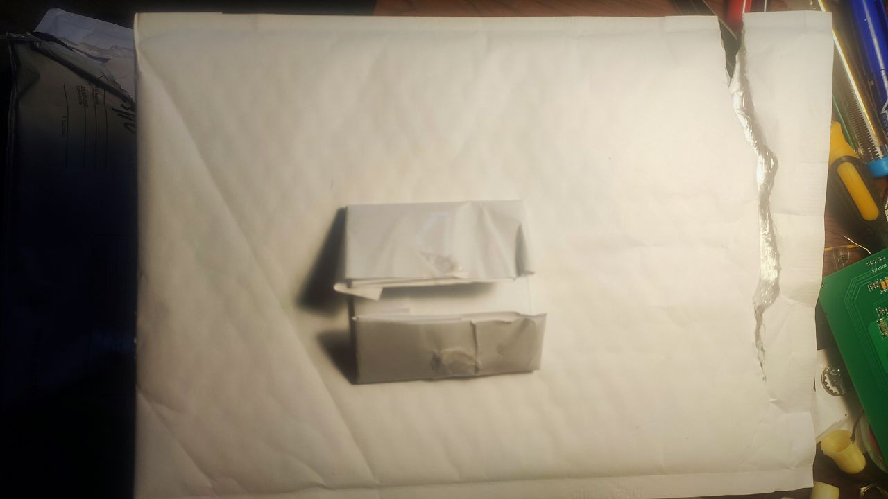
What goes inside is not always consistent and depends on board complexity and their quantity. Simplest 2-layer boards with tiny size can just be poured inside with no additional protection. In most cases though, they provide boards sandwiched between pieces of plywood, each covered with paper to prevent rubbing, which is nice. In our case, well... We just got them hand-wrapped inside some A4 paper with tape. Honestly, this is the first time I get boards in this kind of "package" from them, and it is Ok for simplicity, quantity and purpose of my PCBs, but it is not Ok for me)
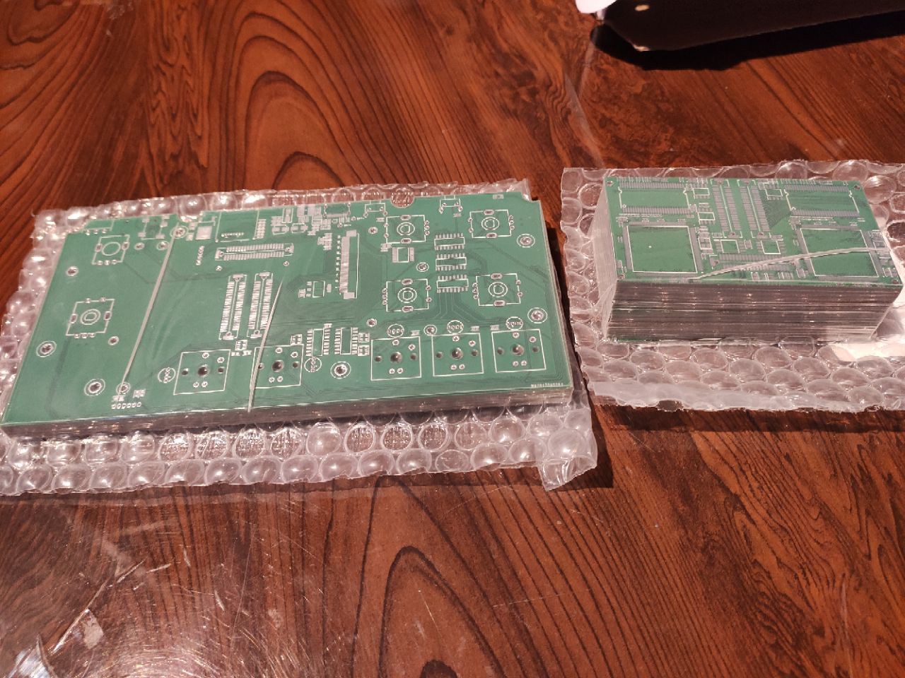
Boards
Now we can evaluate the quality of the boards and take look at them in more detail. Let's put them under a microscope! But before this, I have to say that it would be unfair to compare these two manufacturers today, because we got completely different boards from them with different specs and number of layers, but rather just observe some eye-catching details and possible differences that can be noticed.
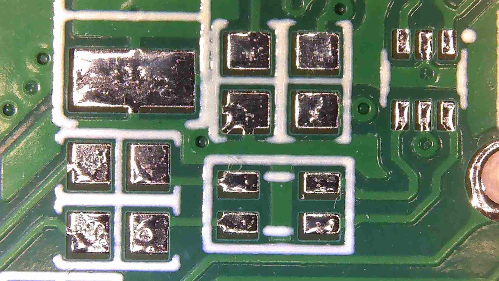
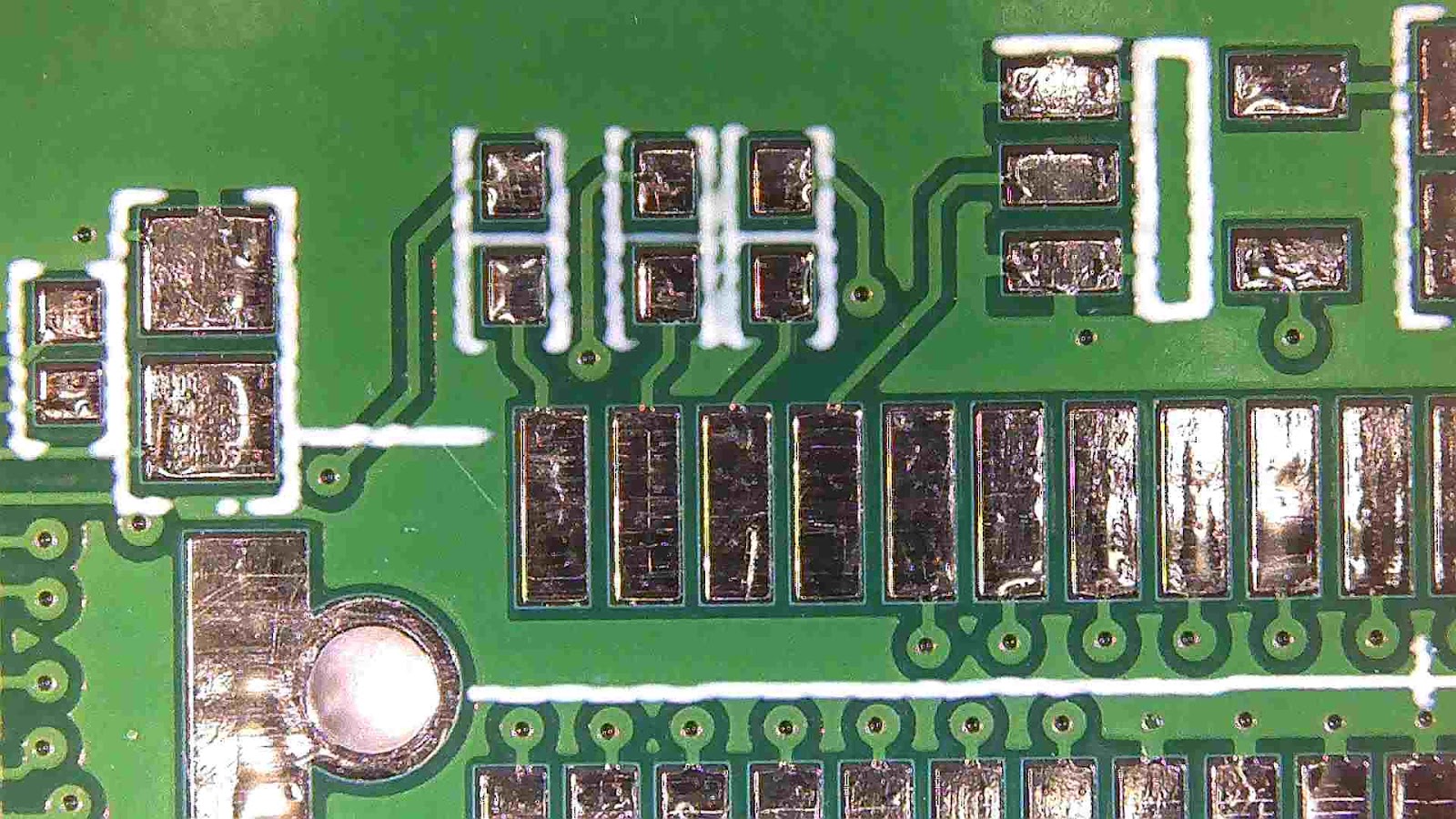
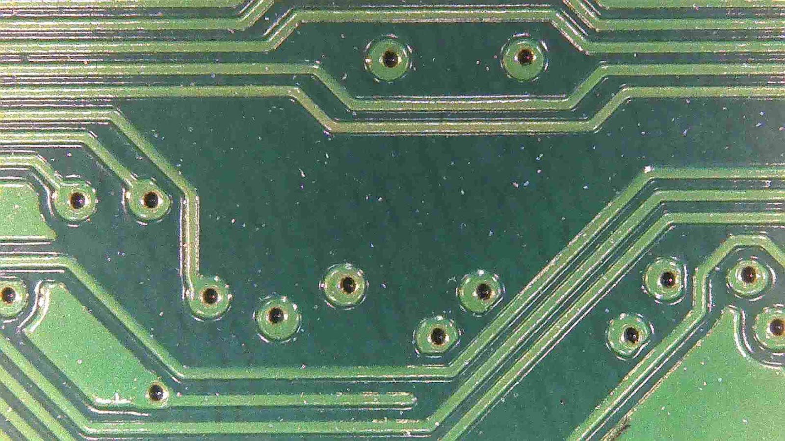
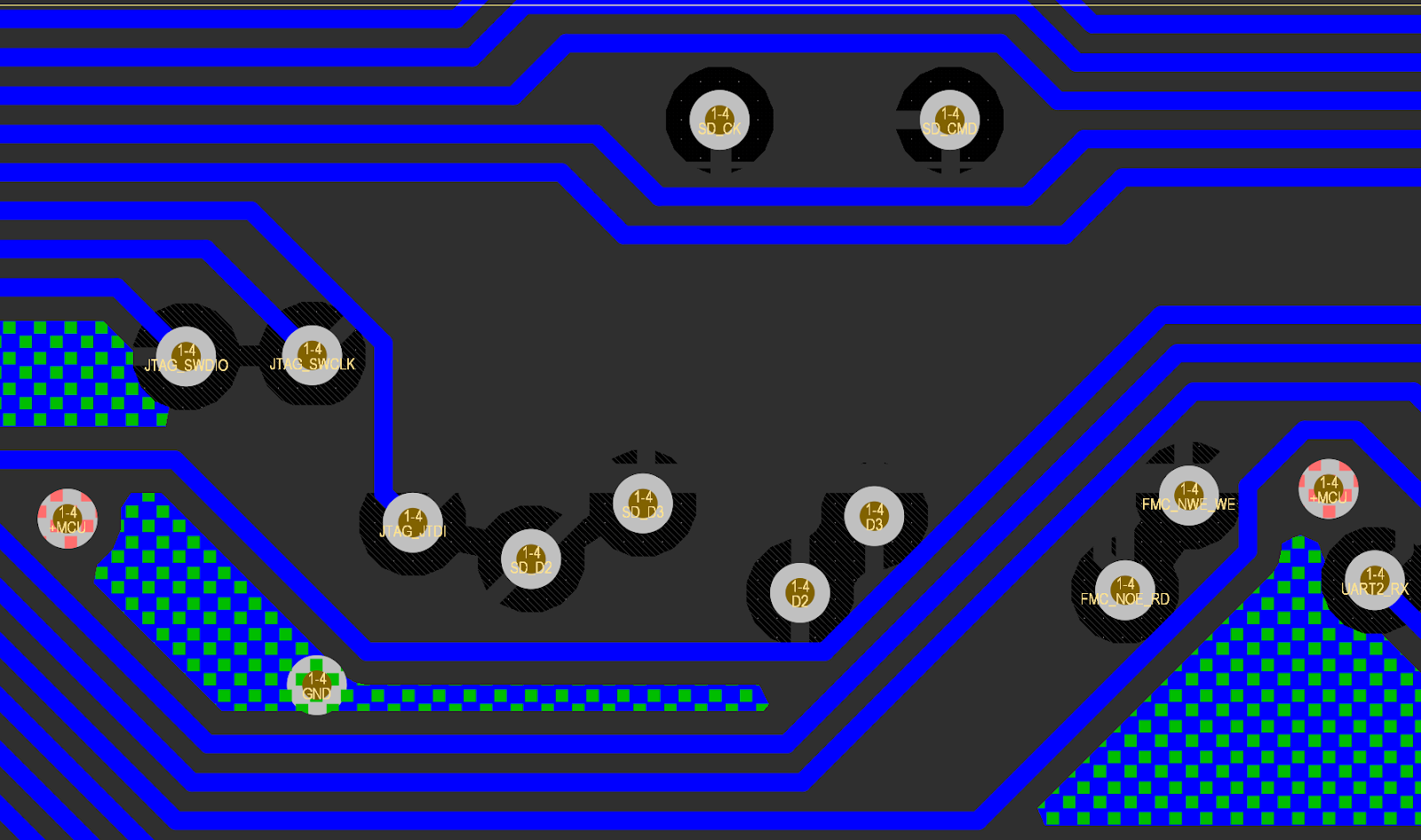
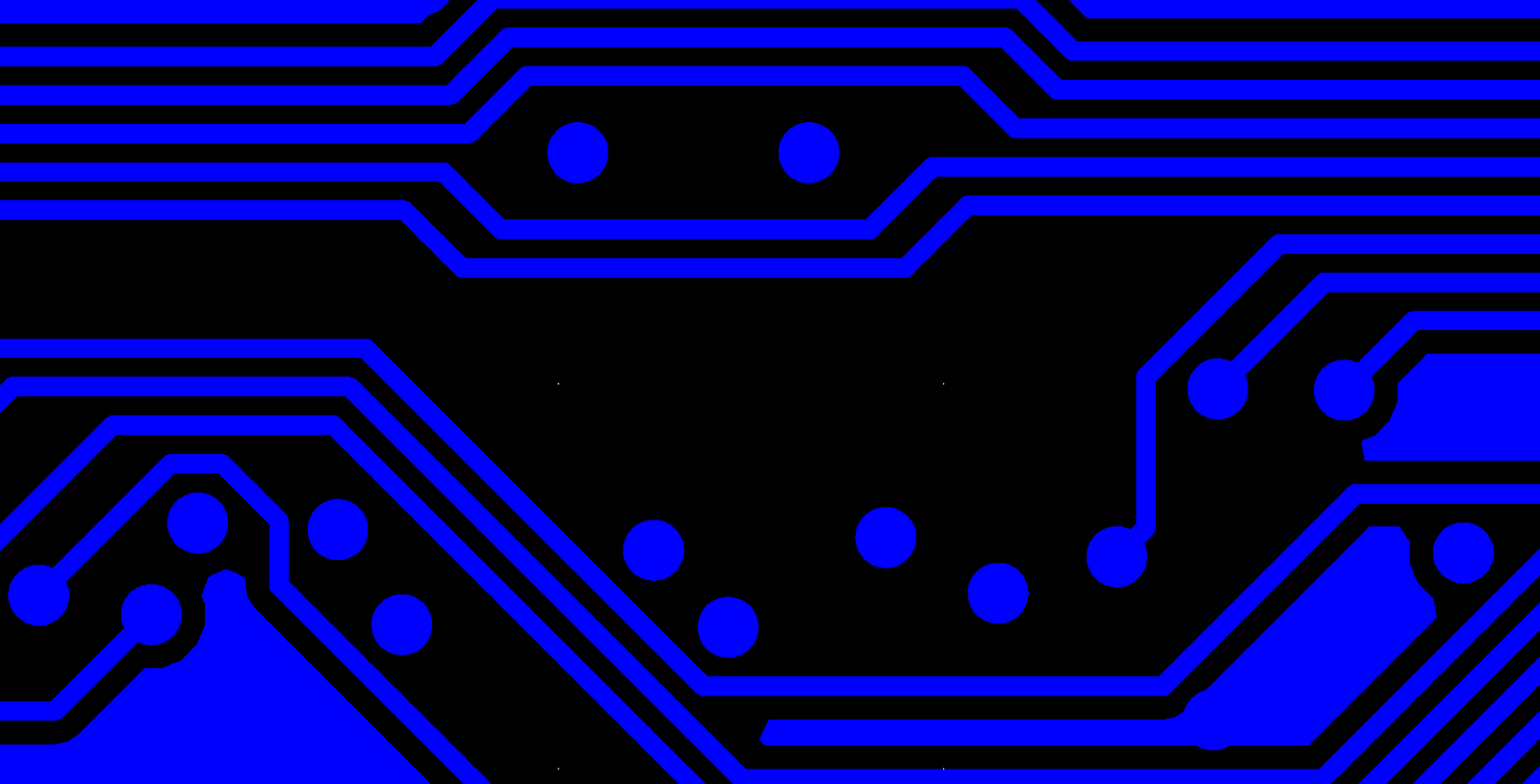
On PCBWay 2-layer boards, we can first see some solder mask misalignment with all the pads. It is not too big, but noticeable for smaller pads like on picture above. it is also fixed in size and direction along the boards and across them, all the pads fit into mask openings, so I guess it should be Ok for 2-layer lowest-tolerance boards.
The silkscreen is not the best but readable, you can notice it has some wobbliness in one direction:
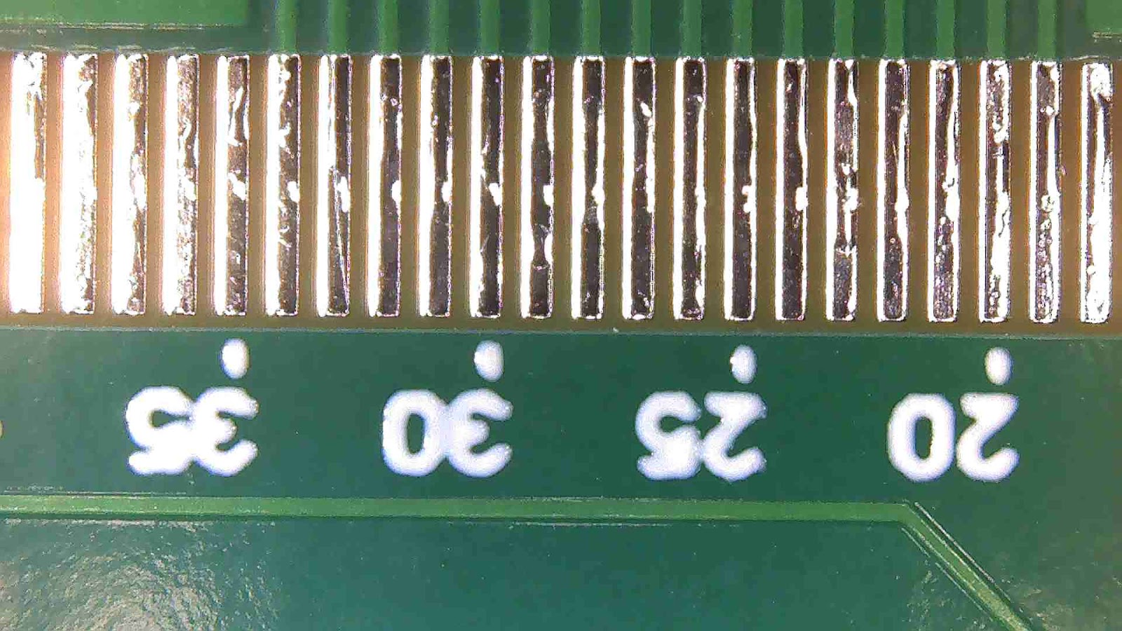
Below is the smallest silkscreen text I use (25 mil height / 5mil stroke), which came out nicely:
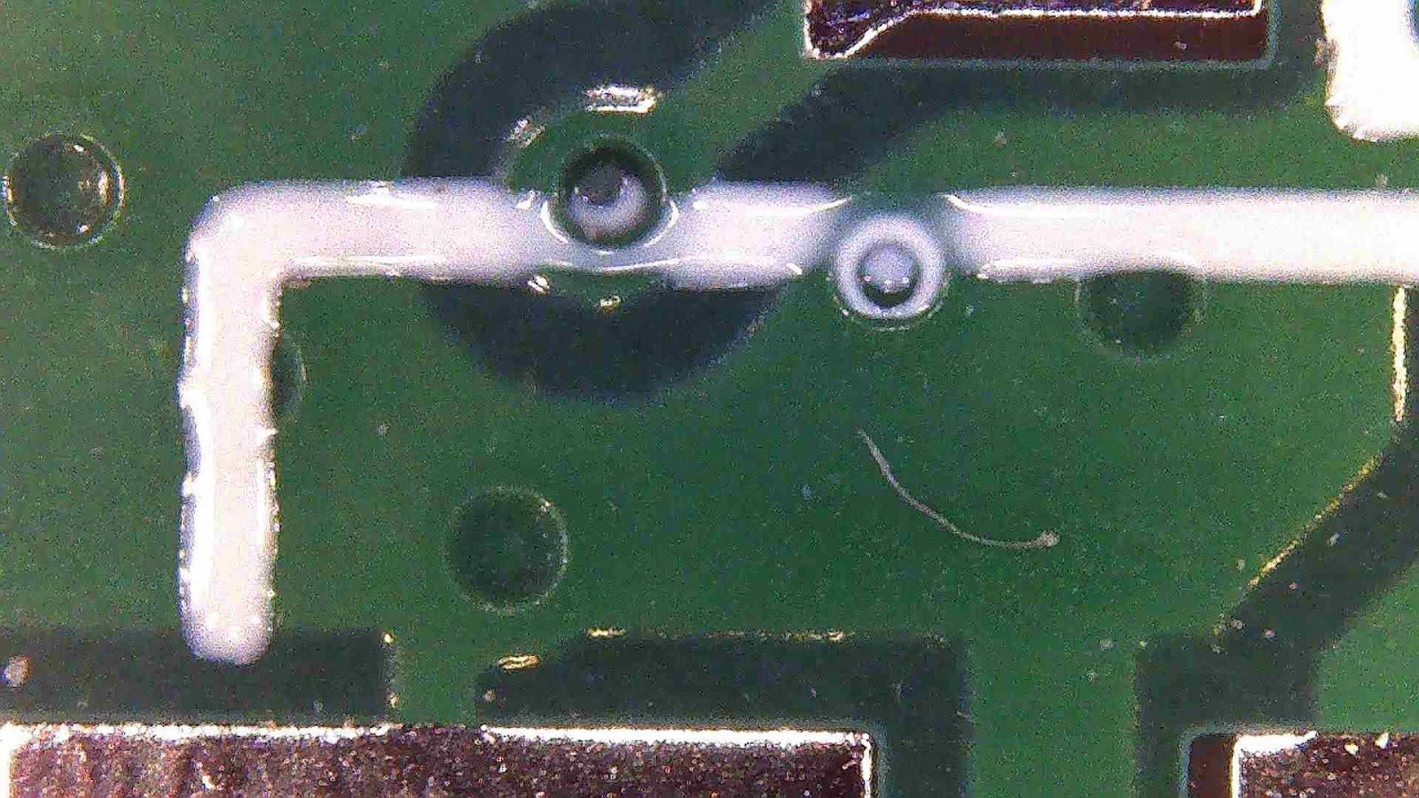
VIAs are well covered by the mask, and some of them are even filled with it. Here's also an example of silkscreen crossing the VIA:
This is a higher tolerance 4-layer board - solder mask tolerance is also higher, but still a bit misaligned.
Interestingly, I noticed that some VIAs have a slightly different shape than in my CAD. They seem to have been enlarged wherever possible and then trimmed to ensure minimal clearance is met. This gives more room for drill holes, as they always have some positioning error. Most likely, this is the result of post-processing my gerbers by the technicians or their automatic software, as on the MCU board, I used the smallest possible VIA sizes of 0.4/0.2 mm. On the main board with bigger and easier to manufacture VIA size 0.6/0.3 mm, they all look round.
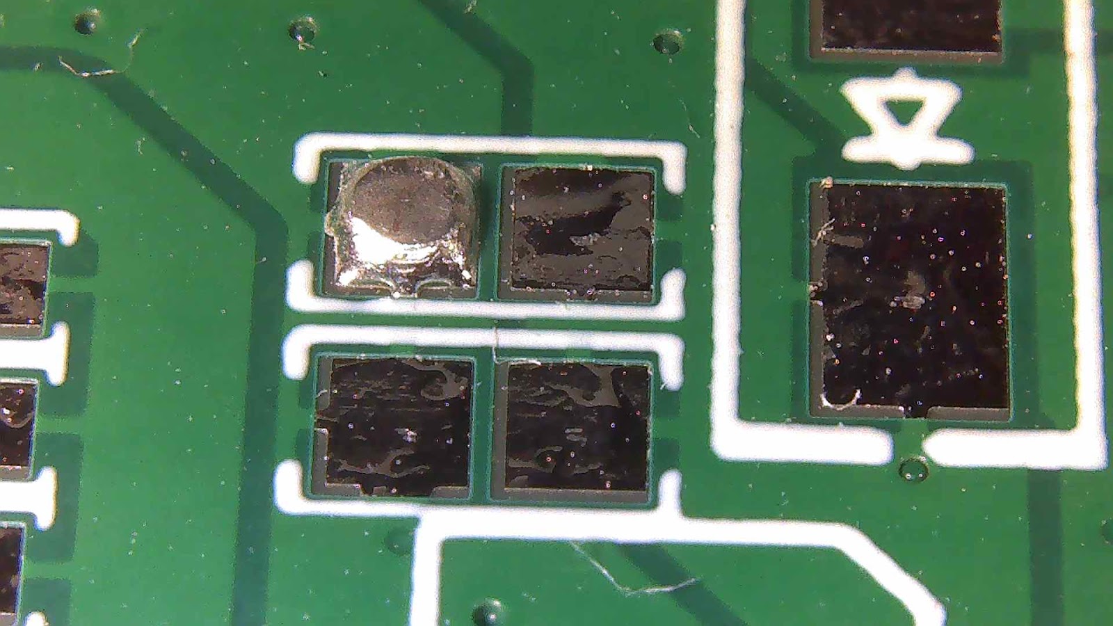
Oops, a soldering mishap! It's not a big deal for me since I solder everything manually, but for automated assembly, it would be a serious issue:
Although, out of all the boards, this only happened on one. I hope it's just a drawback of the inexpensive manufacturing process, and for serious serial orders, more careful control is in place.
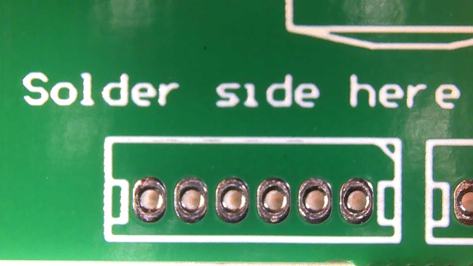
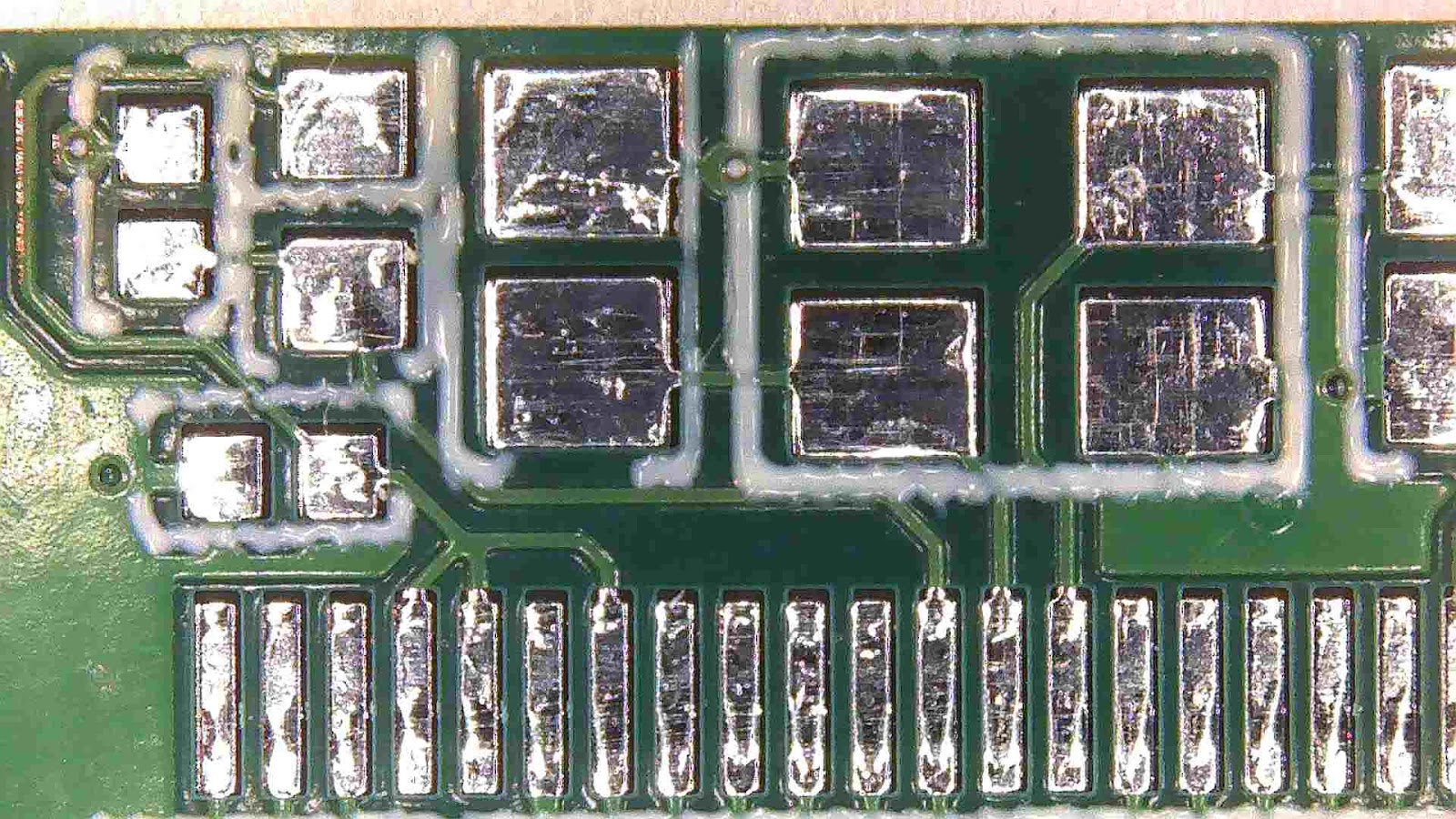
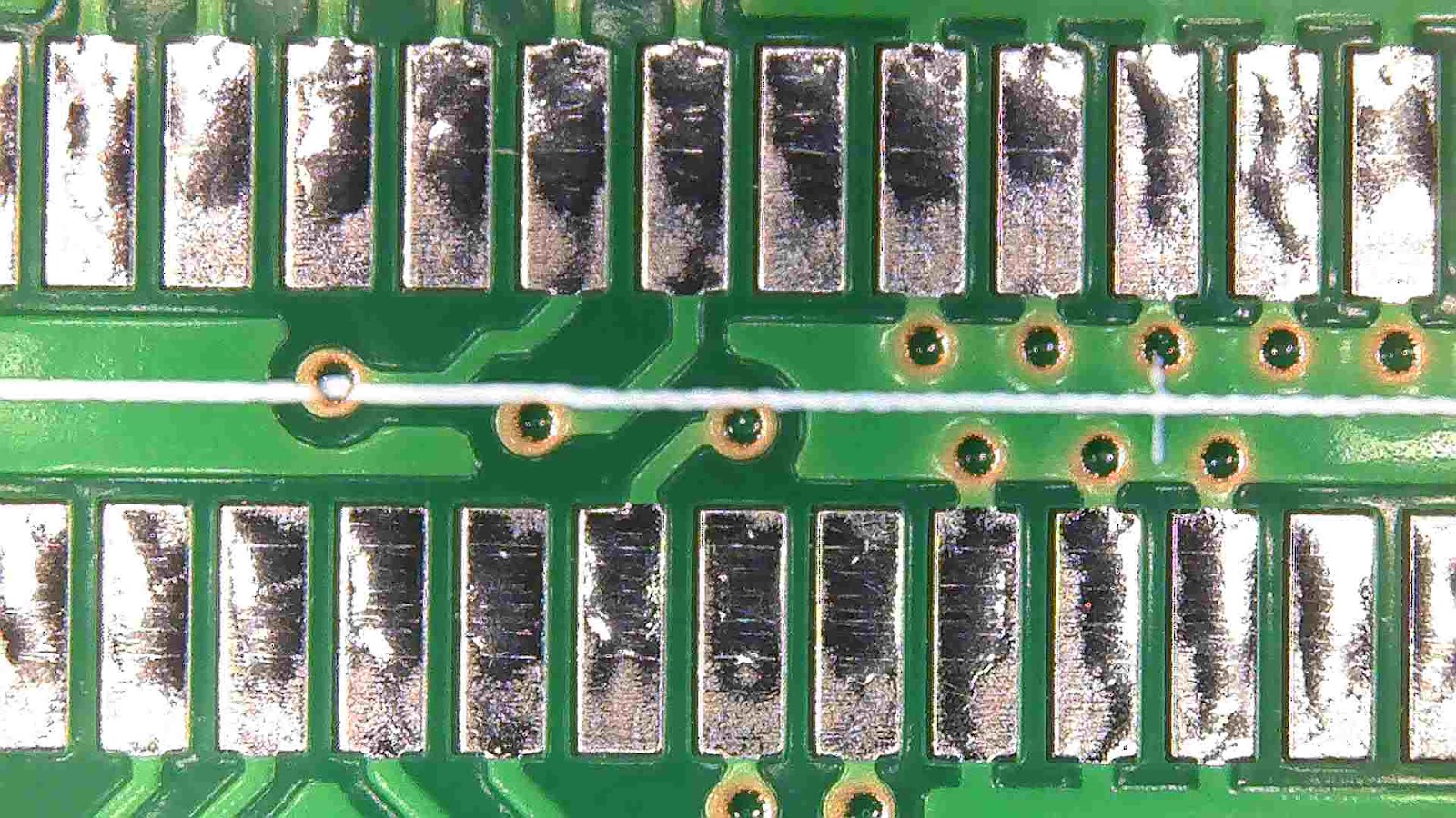
As for our local manufacturer, we can see that their standard solder mask is kind of more liquid and thin, which allows to make much smaller mask opening and wider sliver, but in expense of poor VIA cover:
The silkscreen is good, the line wobble is still there, but is barely noticeable:
Here is the text with 40 mil height and 8 mil stroke:
Other than that, I haven't noticed anything special - just simple 2-layer boards, as one would expect, but with huge labour and engineering fee for their simplicity, as a downside.
Conclusion
All in all, aside from differences, both manufacturers satisfy our need for good quality PCBs for our project. All traces and pads on all boards seem fine, and solder mask and silkscreen issues do not affect boards functionality. PCBWay's boards are good value for the price, and are just what we need for our project.
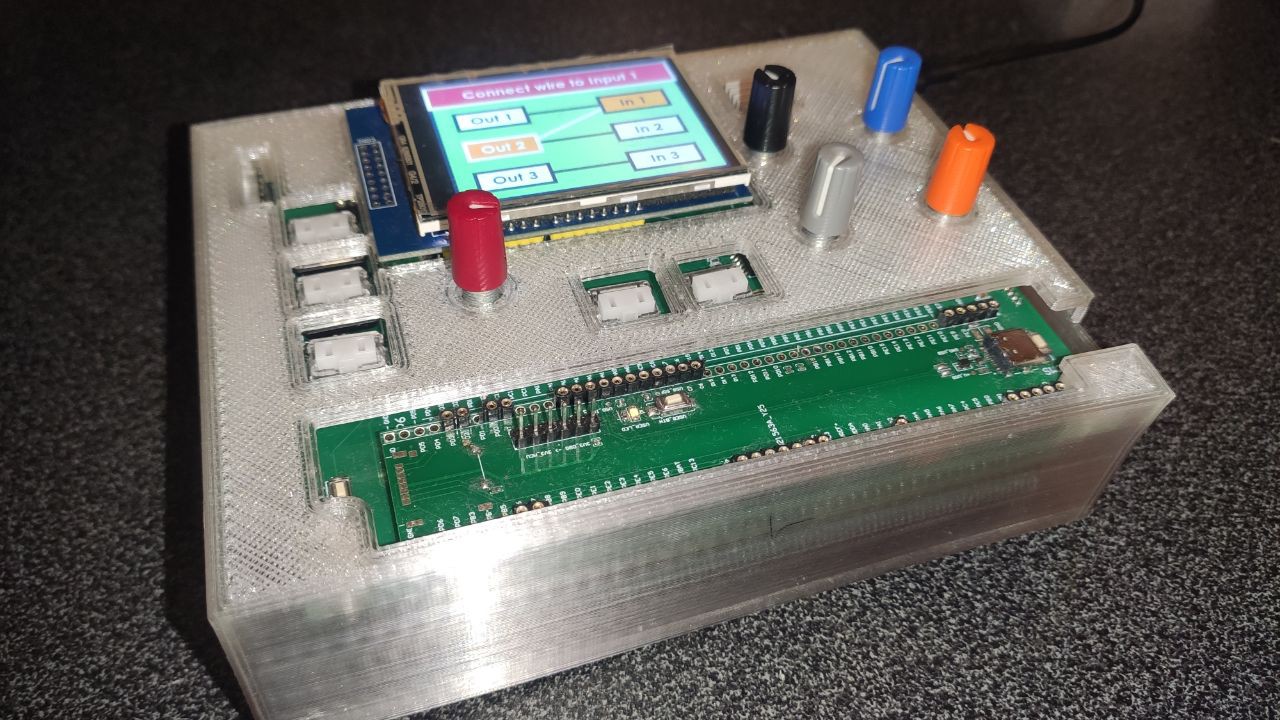
As Predtech4 shares, he finally managed to get the SD card to work on our prototype. As a result, almost all important parts of our first prototype have been tested: we now have a fully functional audio system, established interaction between UI and Audio microcontrollers, display output is functioning, and our GUI, created with TouchGFX, works seamlessly. From the shortcomings, RATelectro made a poorly performing power supply unit that overheats and needs to be revised. Additionally, we haven't yet finalized the battery scheme and charging.
---------- more ----------
Our status:
Currently, we are preparing to create a prototype that resembles a pedal more closely. This prototype will be enclosed in a casing to retest our electronics and their layout within this casing. It will also have the appearance of a more or less finished device that can be handed to someone for testing and feedback.
For now, we've decided to divide our electronics into the following boards:
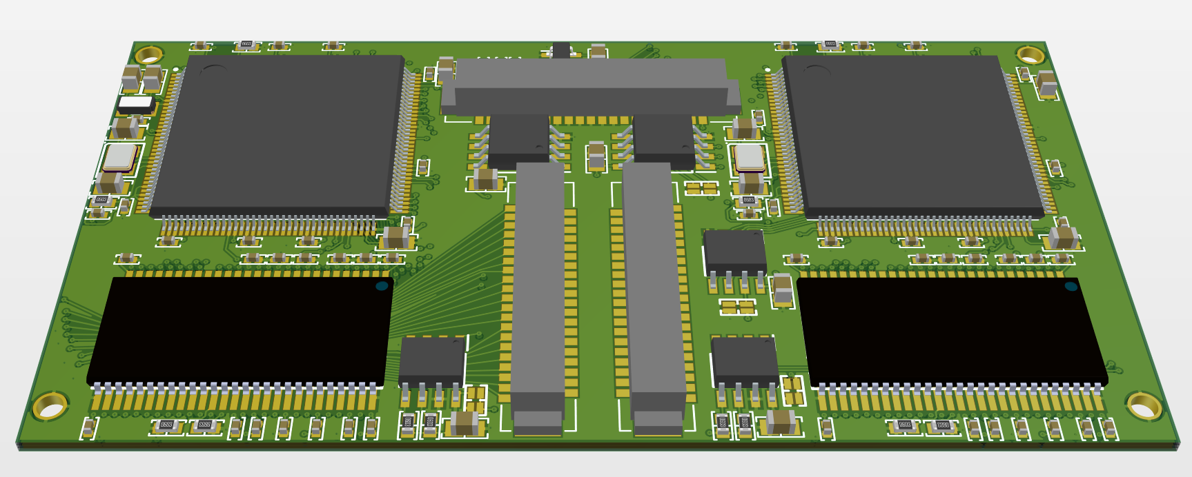
MCU board:
This board houses the UI and Audio MCUs, as well as SDRAM and optional chips like QSPI FLASH, PSRAM, and EEPROM. This board connects to everything else via mezzanine connectors.
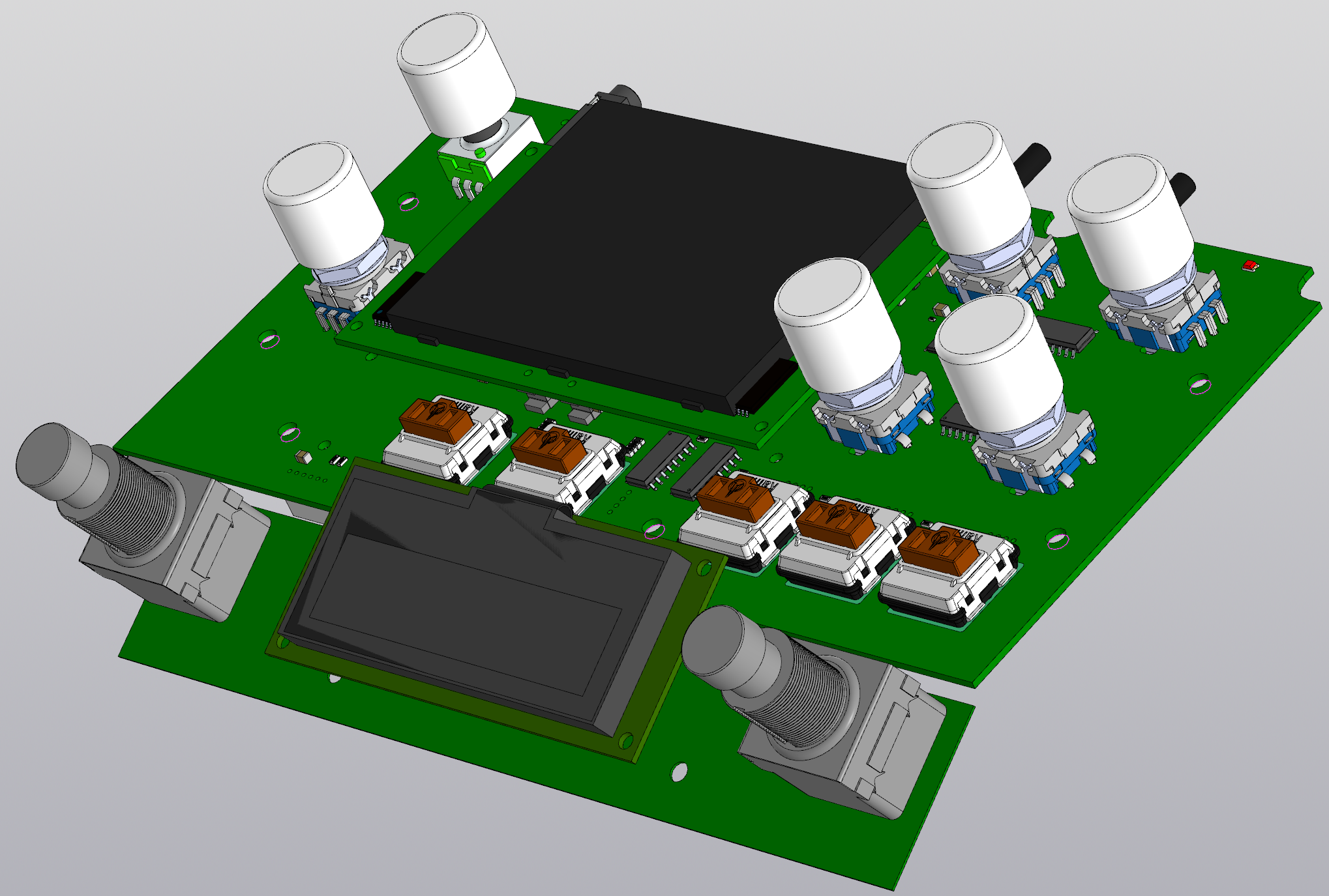
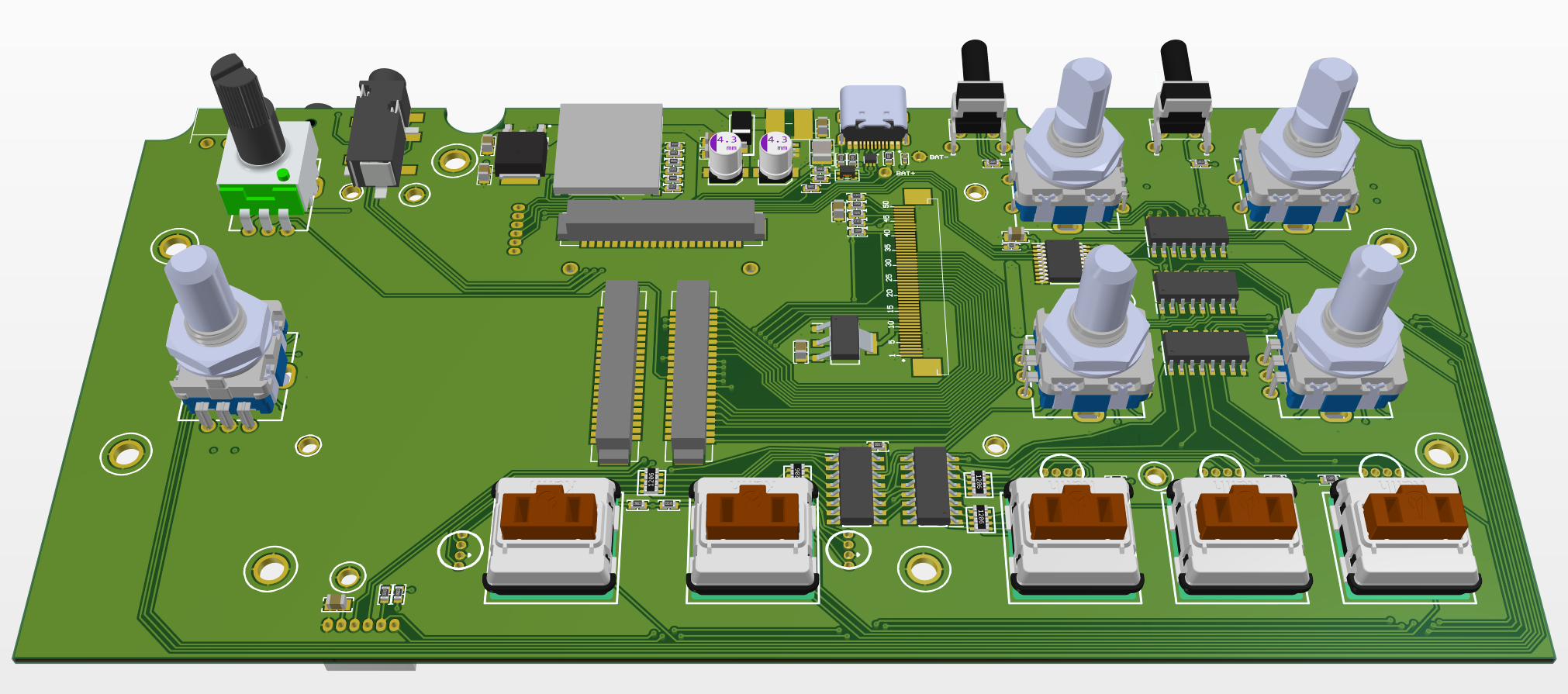
Main board:
This board contains all the connectors on the rear panel, as well as encoders, LEDs, and buttons. It links the MCU board to the codec board and includes the power supply block and an LCD connector.
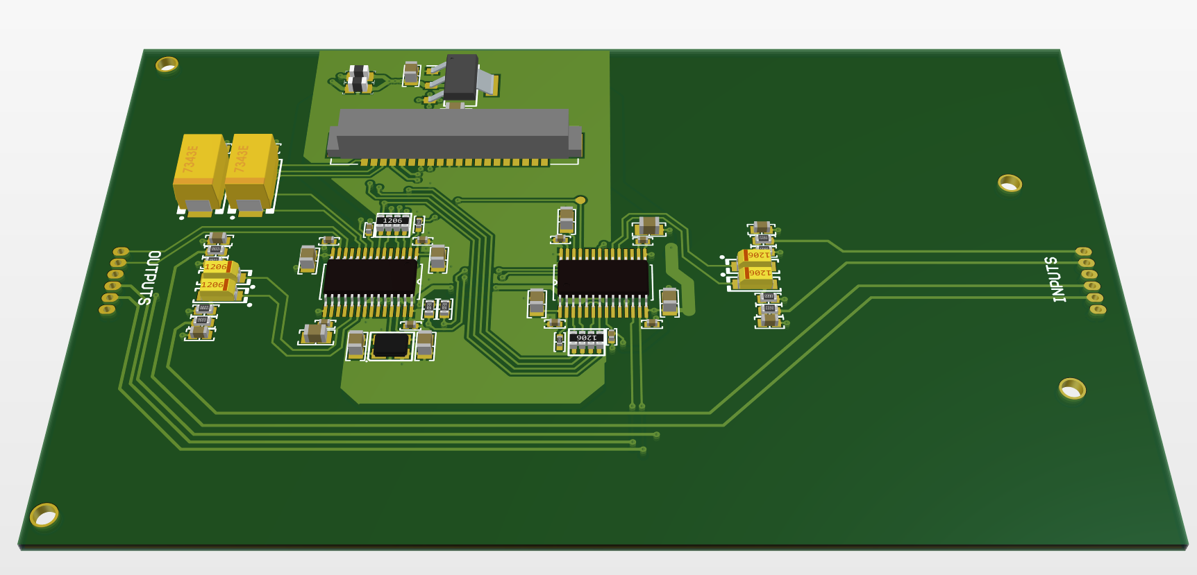
Codec board:
This separate board houses the audio frontend and a dedicated power source for analog circuits.
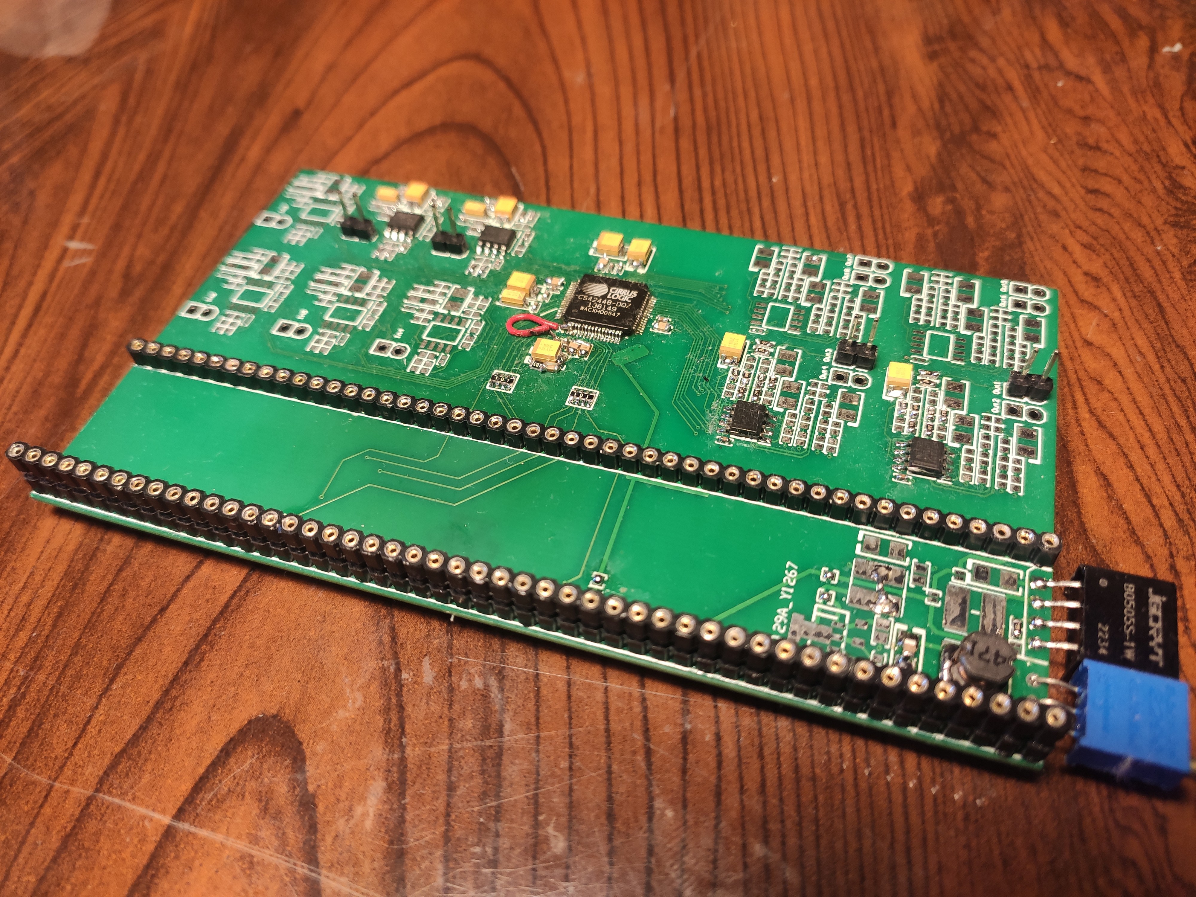
Lately, I've been working on the proto board of a cs42448 codec, which would allow us to have 6 audio inputs and 8 audio outputs. It's a very convenient and cool chip, but as I understand, it has been discontinued, although it can still be purchased in some places.
I designed a board for our stacking prototype and wrote a basic code to configure it through I2C. I set up the SAI in TDM mode for STM32, but so far, I haven't been able to hear any sound.
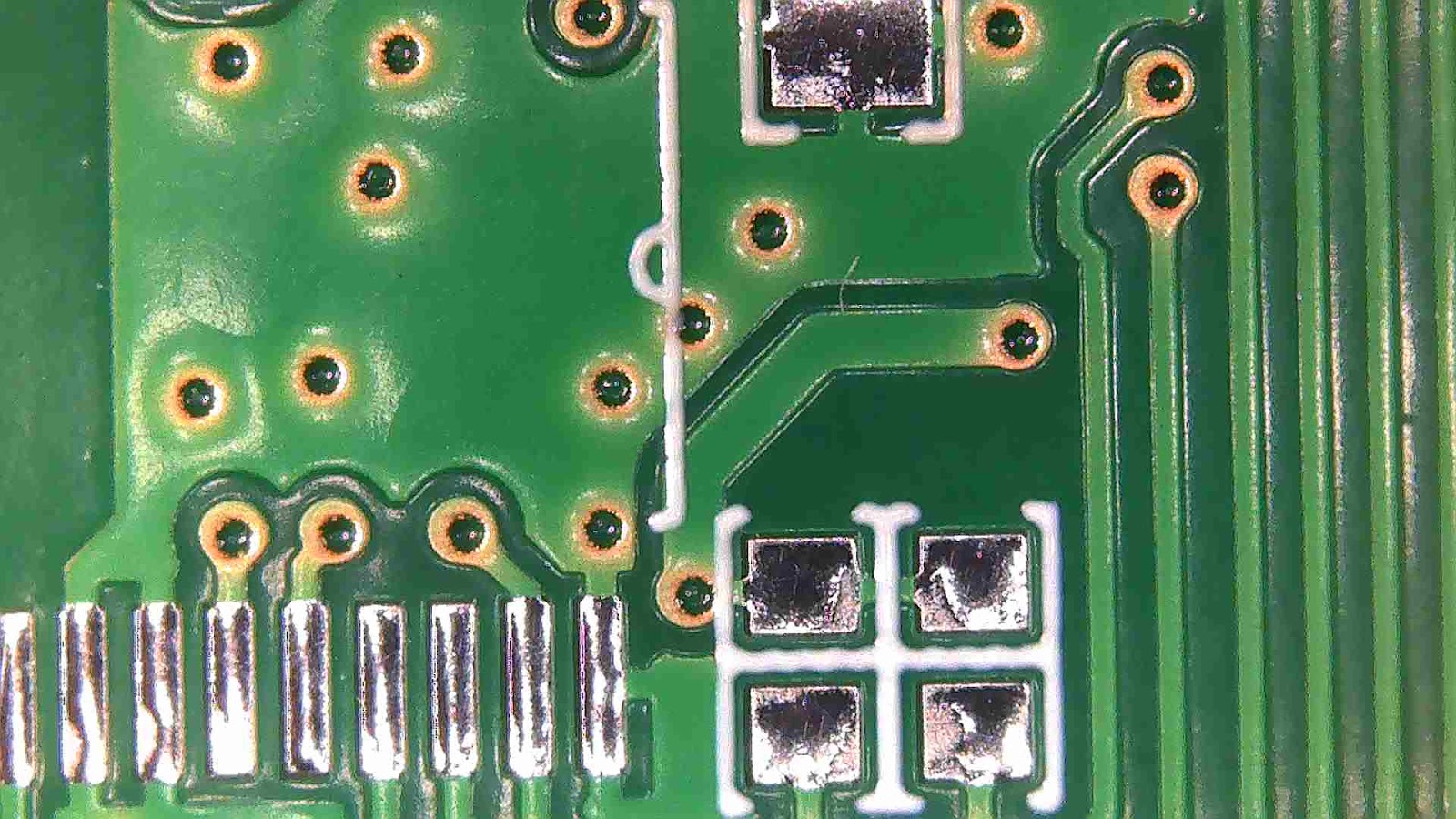
Here we go again, red wire and traceless SMD soldering
I feel that it might be worth exploring other more popular solutions, even if they involve a more complex connection to STM32 (something like three SAI simultaneously (or 2 SAI + 2 I2S channels), but that would only give us 6 channels on output, and we would like 8 channels to have a separate stereo channel for headphones). As I mentioned earlier, most likely, for headphones, I'll use a simple stereo SPI DAC, possibly with a built-in amplifier.
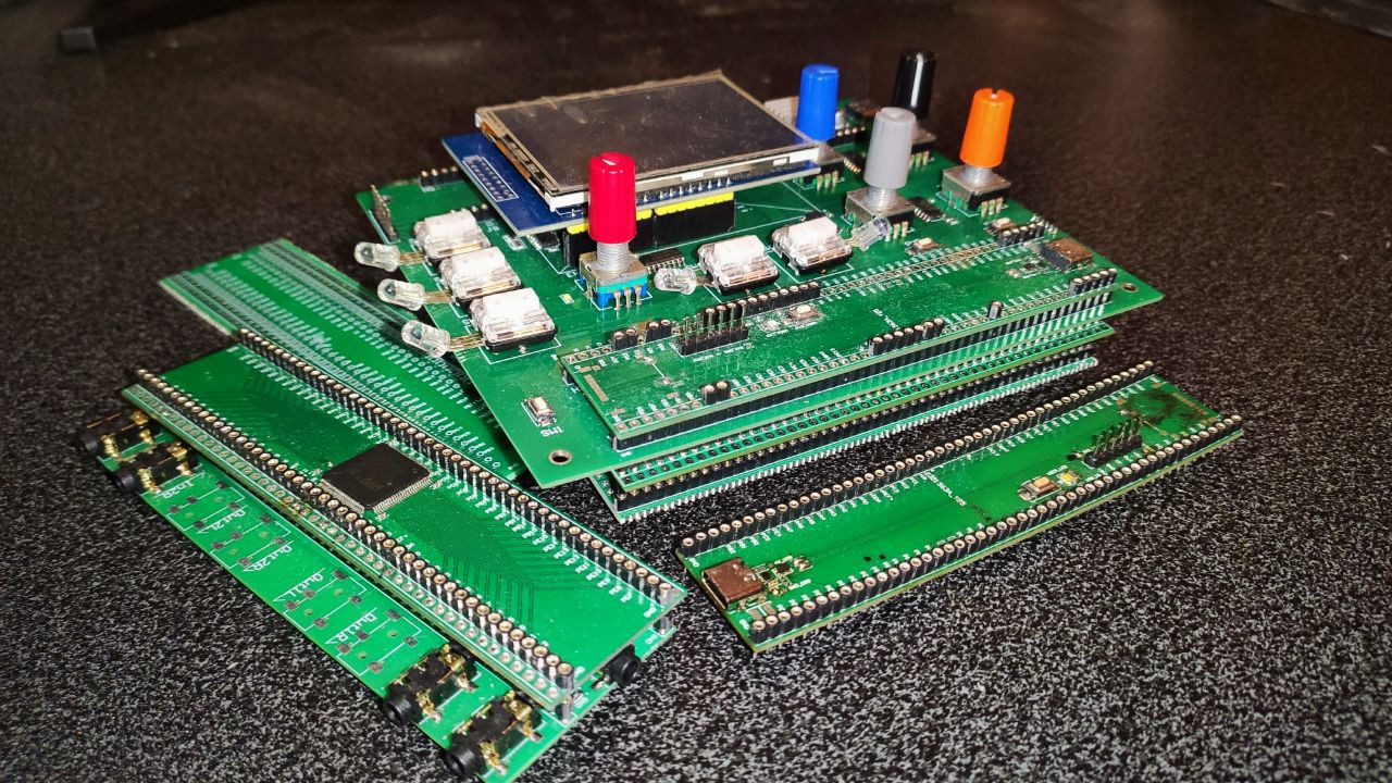
Given our past experiences creating various layouts and prototypes for audio devices, we've developed a keen awareness of our bug-prone areas in hardware (primarily my responsibility, hehe). Consequently, we've decided to adopt a segmented approach, creating a "sandwich" structure. This allows us to troubleshoot efficiently – in case of failure, we only need to redesign the specific board where the issue was identified.
Moreover, this strategy optimizes vertical space utilization, a critical consideration for compact devices like our pedal. Making these boards segmented also accelerates development a bit, providing more routing space and reducing the required number of layers, accommodating a greater number of components.
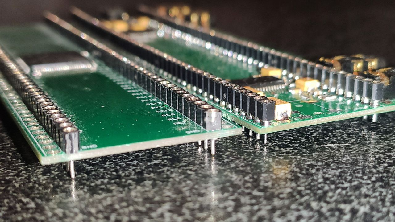
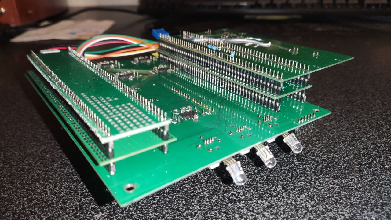
Initially, we divided our device into even more boards, assigning each board to a specific function. Stacked circular headers facilitated the connection of this array of boards:
On this old prototype, we tested the functionality of most essential circuits that will be integrated into our later designs. We also placed it into some sort of case to carry it around.
So now we are ready to sketch out the first design of a more pedal-like case, and more practical PCB layout that would fit into.
During our experiments, we found it more convenient to split our computing hardware into two parts. The first part, which we call UI, handles everything that interacts with the user – processing button presses, knob turns, LED indicators, and displaying information on the screen.
Since this microcontroller (MCU) is connected to the display, we decided that it would run the entire pedal operating system – all menus, user interaction with audio parameters, the file manager with the SD card, and everything related to power on/off.
The second MCU, which we refer to as AUDIO, focuses solely on audio processing and is connected to the UI via UART for command exchange and via SPI for audio data exchange (for example, to retrieve an audio sample from the file system on a memory card or vice versa, to write it there).
Firstly, this approach significantly boosts performance, as audio and user interface processing are well-separated and differ greatly in speed. Secondly, even if we decide to radically change one part, the other can remain the same. For example, we could swap audio MCU with DSP, which would be transparent to UI MCU since we are leaving the UART+SPI protocol the same.
For the MCU, we decided to go with what is most familiar to us and has maximum functionality, and what is available for purchase – for us, it's the STM32H743ZIT. It comes with a DRAM controller, a large amount of built-in FLASH memory to simplify development, and an FMC interface for connecting most displays. We also opted to use the same MCU model for both processors to simplify development.
As for the audio frontend, we chose the popular WM8731 audio codec and connected two pieces to get 4 inputs and 4 outputs (or 2 stereo inputs and 2 stereo outputs). This codec is easy to work with, and we have already used it in previous projects, making it a safe and reliable option for us. However, to achieve 6 inputs and 6 outputs, plus a stereo headphone output, we will explore more suitable alternatives in the future. Or maybe we simply add the third WM8731 and some simple SPI / I2S stereo DAC for separate headphone output.
Hi Hackaday! We're Roman, Dima and Alex, and we're making FXcursion – a versatile, compact audio multi-tool in a guitar pedal form factor. This project was born from our love for electronic music and hardware design.
Originally, we had plans to make an electronic synthesizer, but it was a bit over our heads, so we decided to release something simpler first. This is a scaled-down version of our initial vision – an effects pedal with a simple user interface, basic audio input/output, and some processing in between.
FXcursion can perform basic tasks across various usage scenarios, and eliminate the need for separate mixer, FX pedal, looper, and recorder or USB-Audio interface, which together occupy a lot of space, require mains power or just need a lot of cables and connections if used at the same time. It still is interoperable with any other hardware components, so you can combine it with whatever hardware you have and use FXcursion for the rest of the tasks.
Ultimately though, we want FXcursion to be not just a single product, but a versatile hardware audio platform that can be freely utilized for learning and experimentation by both us and the wider community. In the meantime, we hope to make something you will love and that will help you discover better sounds and be a better musician overall. Follow us on our journey :-)
 Ale
Ale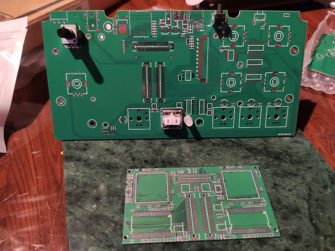
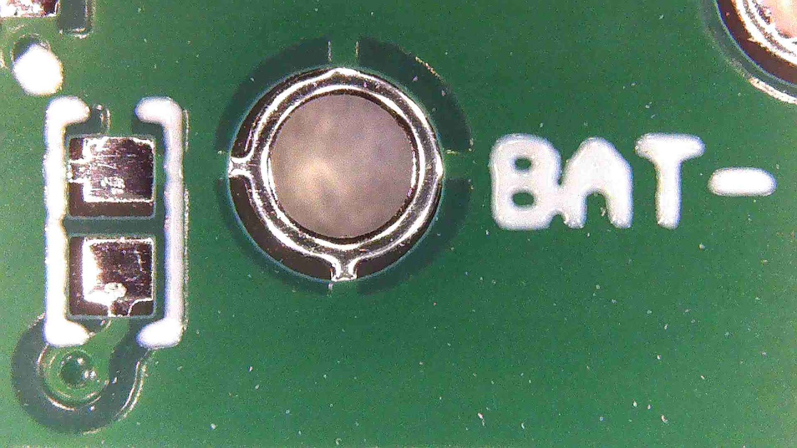

 Here is the text with 40 mil height and 8 mil stroke: