 Human Controller
-
1Caution
Be very careful that NFT images are public and cannot be deleted!
Put masking tape on the lens of the camera module until the blockchain camera is completed. Even after the blockchain camera is completed, put masking tape on the lens when not in use.
Strictly speaking, data stored in IPFS may be deleted if left alone. However, the person who stored it cannot actively delete it.
-
2Installing the App & Deploying the DApp
TOOLS
- PC
- MicroSD Card Reader
- Wi-Fi
- USB Type-C - AC Power Supply
COMPONENTS
- Raspberry Pi 4 Model B 2GB
- SanDisk microSD 32GB Extreme Pro U3 V30 A1
- OSOYOO Raspberry Pi Touch Screen 3.5"
- Raspberry Pi Camera V2
- Adafruit Flat Flex Cables for Raspberry Pi Camera - 200mm (You can use a flat flex cable that came with the Raspberry Pi Camera V2. However, when it is connected to the Raspberry Pi along with a touch screen, the wires tend to break.)
Install the Blockchain camera App on your Raspberry Pi. Deploy the NFT minting DApp (Decentralized application) on the blockchain. Refer the blockchain camera GitHub repository for those instructions.
-
3Printing the parts with a 3D printer
TOOLS
- 3D Printer
COMPONENTS
- 3D Printer ABS Filament
FILES
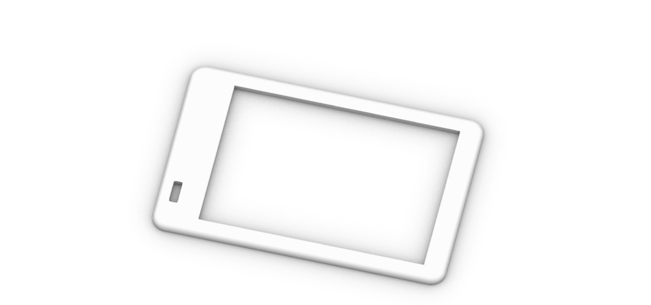
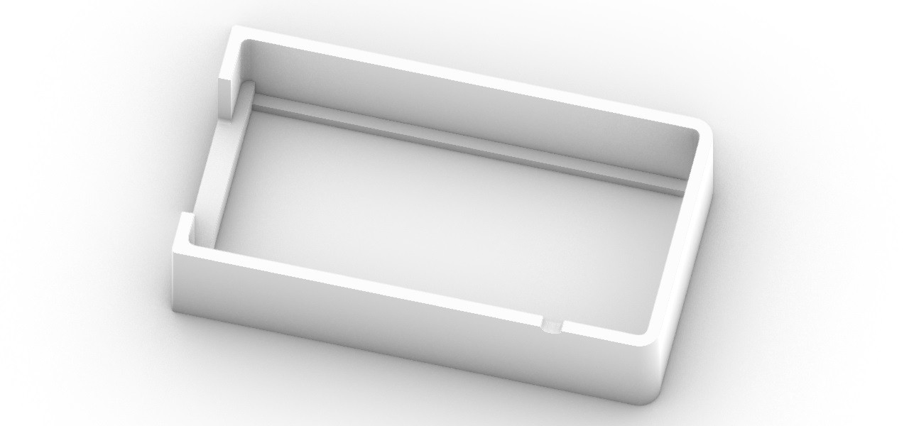
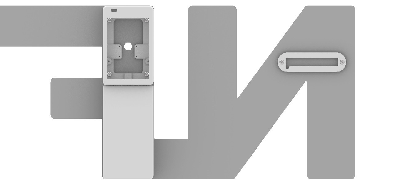
- RPi_Case_Top_v11.stl
![]()
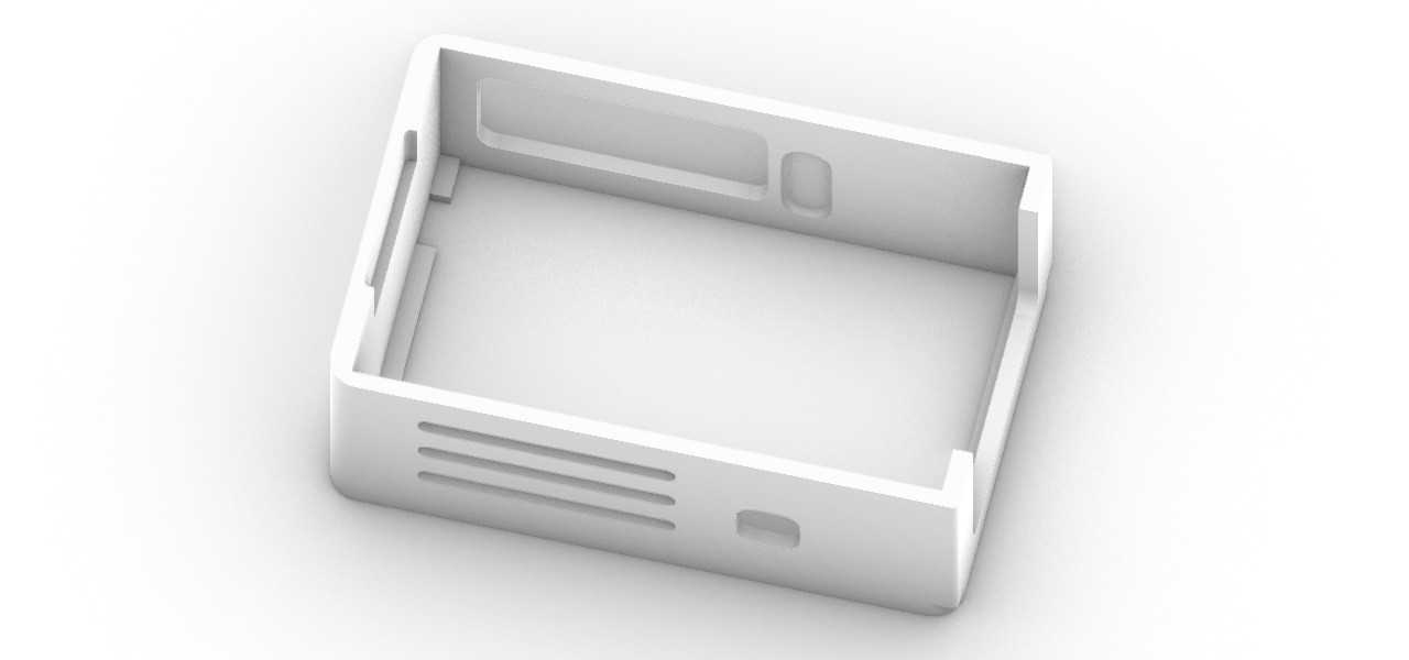
- RPi_Case_Side_v12.stl
![]()
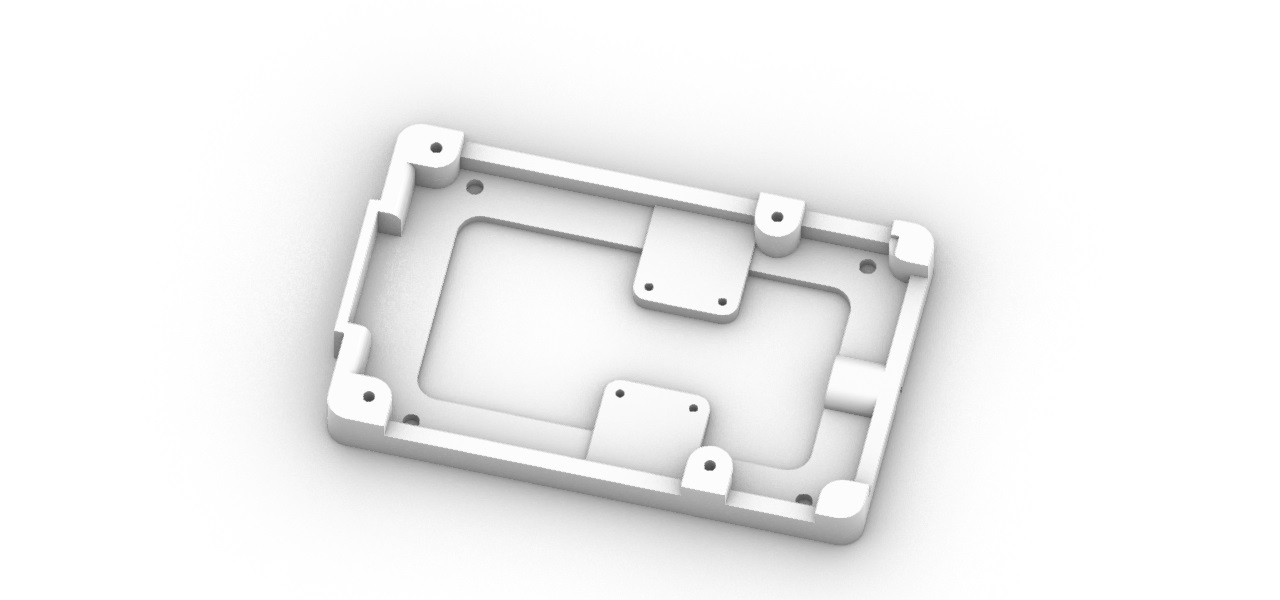
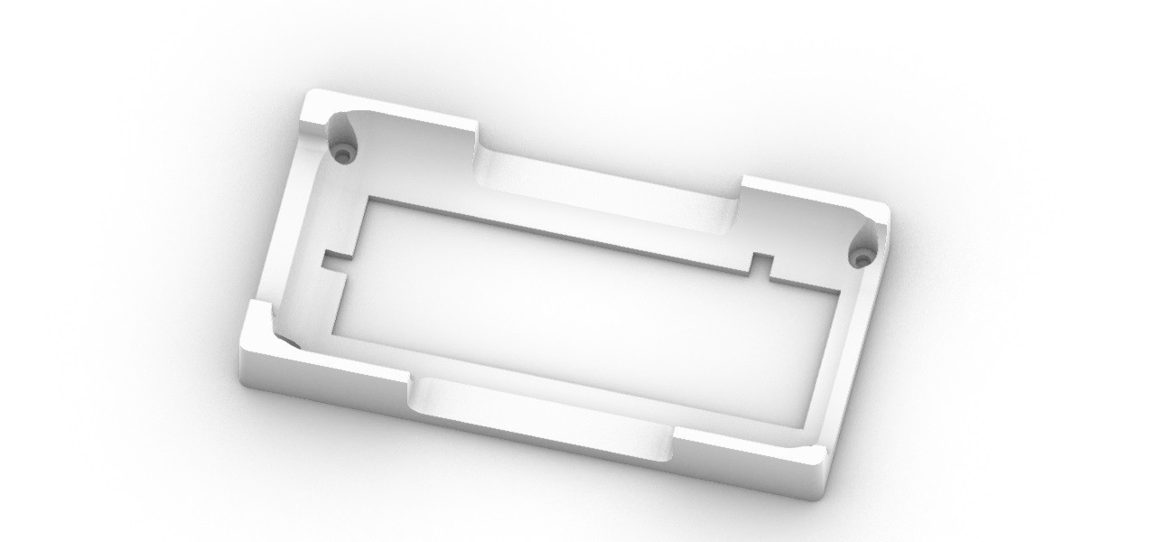
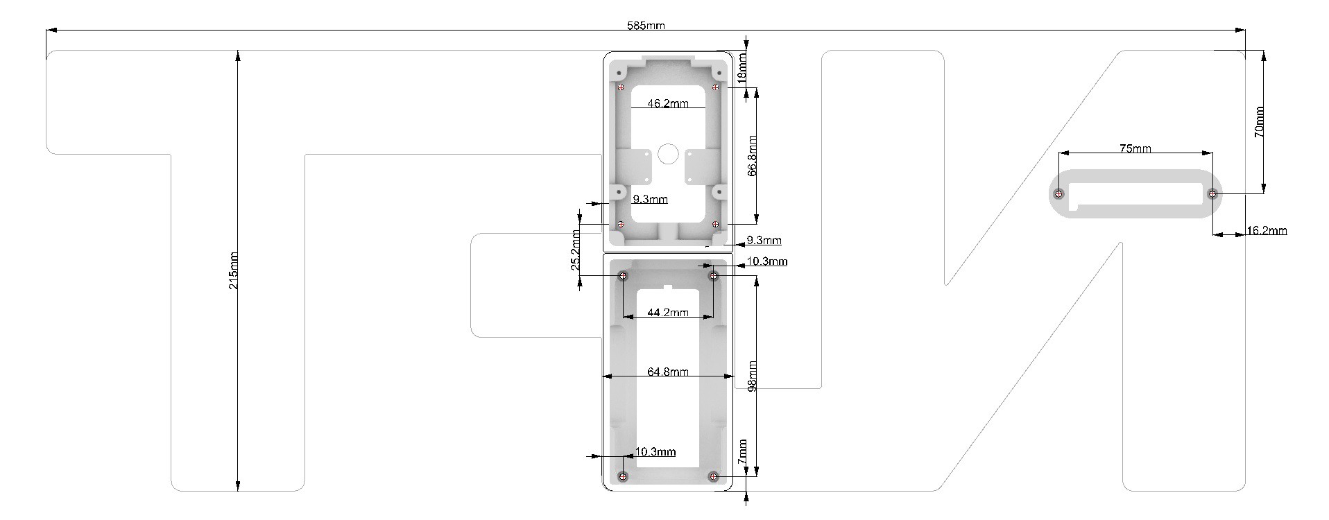
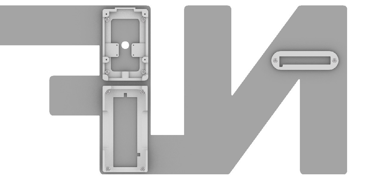
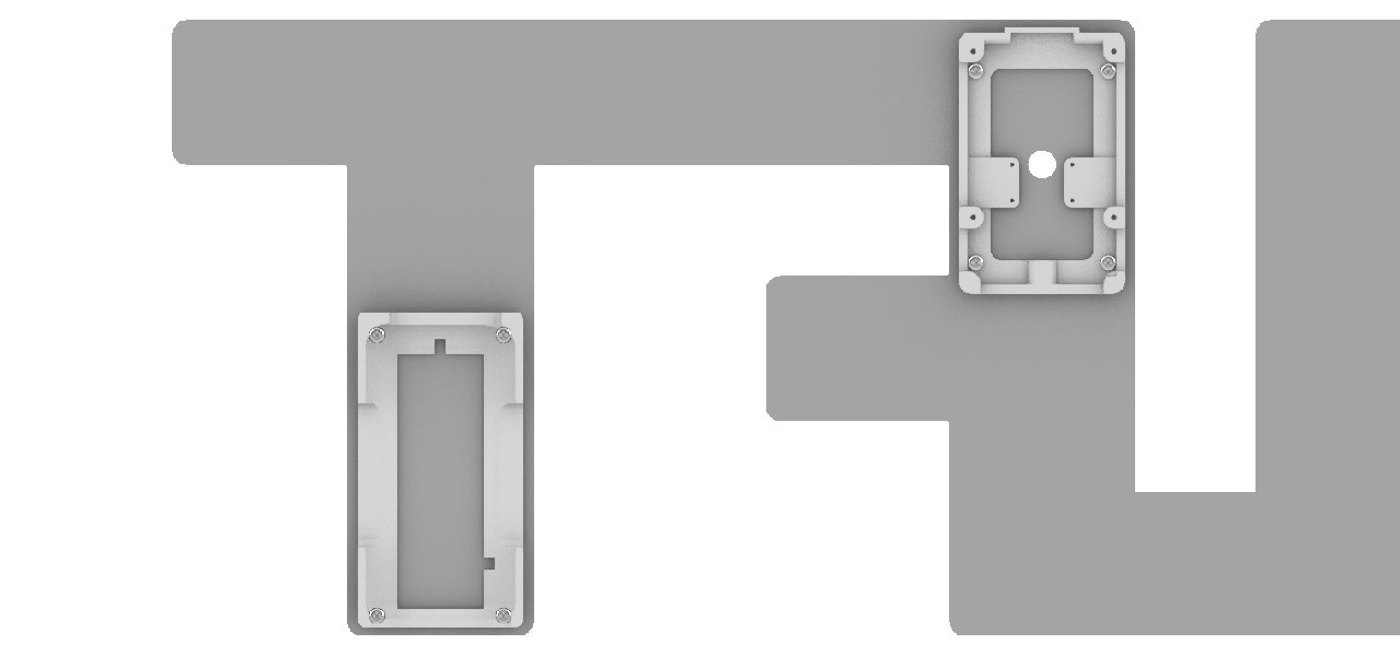
- RPi_Case_Base_v13.stl
![]()
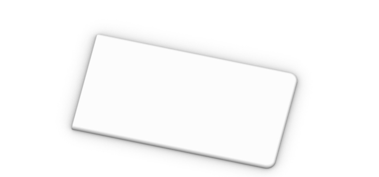
- Power_Bank_Holder_Top_v11.stl
![]()
- Power_Bank_Holder_Side_v11.stl
![]()
- Power_Bank_Holder_Base_v13.stl
![]()
- Shutter_Button_Plate_v11.stl
![]()
- Shutter_Button_Side_v11.stl
![]()
- Shutter_Button_Base_V11.stl
![]()
- USB_Connector_Top_v11.stl
![]()
- USB_Connector_Bottom_v11.stl
![]()
Print all STL files.
For reference, the 3D printer I used is the Afinia H480. The print settings for each STL file are as follows. I only set the Z Resolution to 0.15mm for the parts I want to print accurately.
Z Resolution : 0.15mm, Fill : #1 (Solid), Quality : Normal
- RPi Case Top
- Shutter Button Plate
- Shutter Button Side
- USB Connector Top
- USB Connector Bottom
Z Resolution : 0.25mm, Fill : #1 (Solid), Quality : Normal
- RPi Case Side
- RPi Case Base
- Power Bank Holder Top
- Power Bank Holder Side
- Shutter Button Base
Z Resolution : 0.25mm, Fill : #4 (Big hole), Quality : Normal
- Power Bank Holder Base
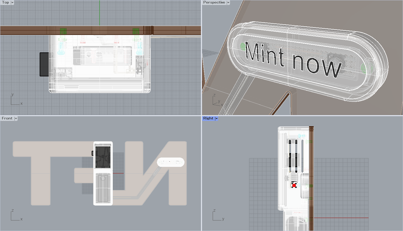
You can modify the original 3D-CAD file with the Rinoceros 7.
- Blockchain_Camera_v13.3dm
![]()
-
4Prosessing of the 3D printed parts
TOOLS
- Glue
- Hand Tap M2
- Hand Tap M2.6
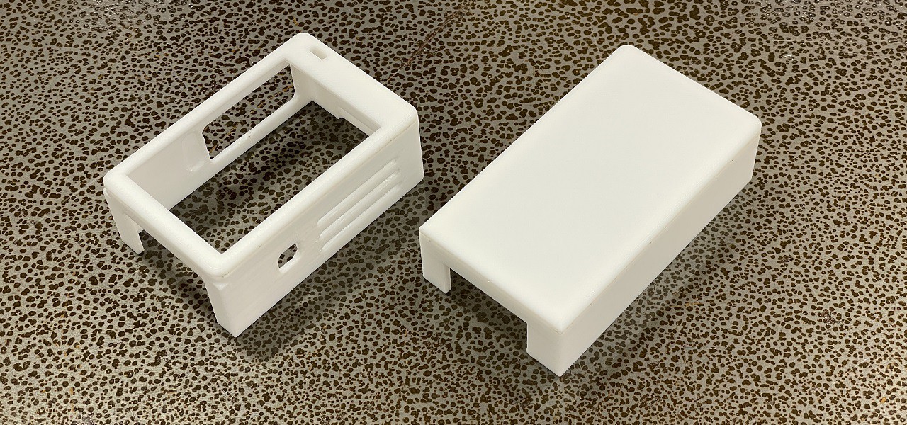
Glue the RPi Case Top and RPi Case Side together. And glue the Power Bank Holder Top and Power Bank Holder Side together.
![]()
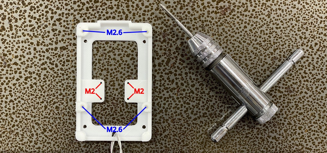
Make M2 and M2.6 threaded holes with hand taps in the RPi Case Base. You can fasten the screws without tapping. However, tapping makes it easier to fasten the screws, and the screw holes will last longer.
![]()
Make M2 threaded holes with hand taps in the USB Connector Top.
![]()
-
5Building the NFT board
TOOLS
- Laser Cutter
- Cutter Knife
COMPONENTS
- Lauan Board 600x230mm 5.5mm thick
- Vinyl Sheet 600x230mm 0.1mm thick x2
FILES
- Blockchain_Camera_Board.ai
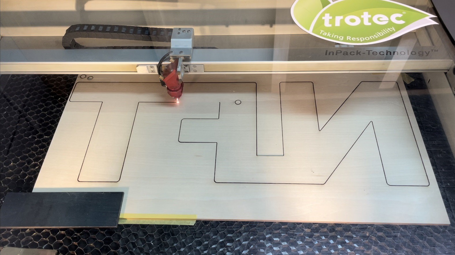
Cut the lauan board with a laser cutter.
![]()
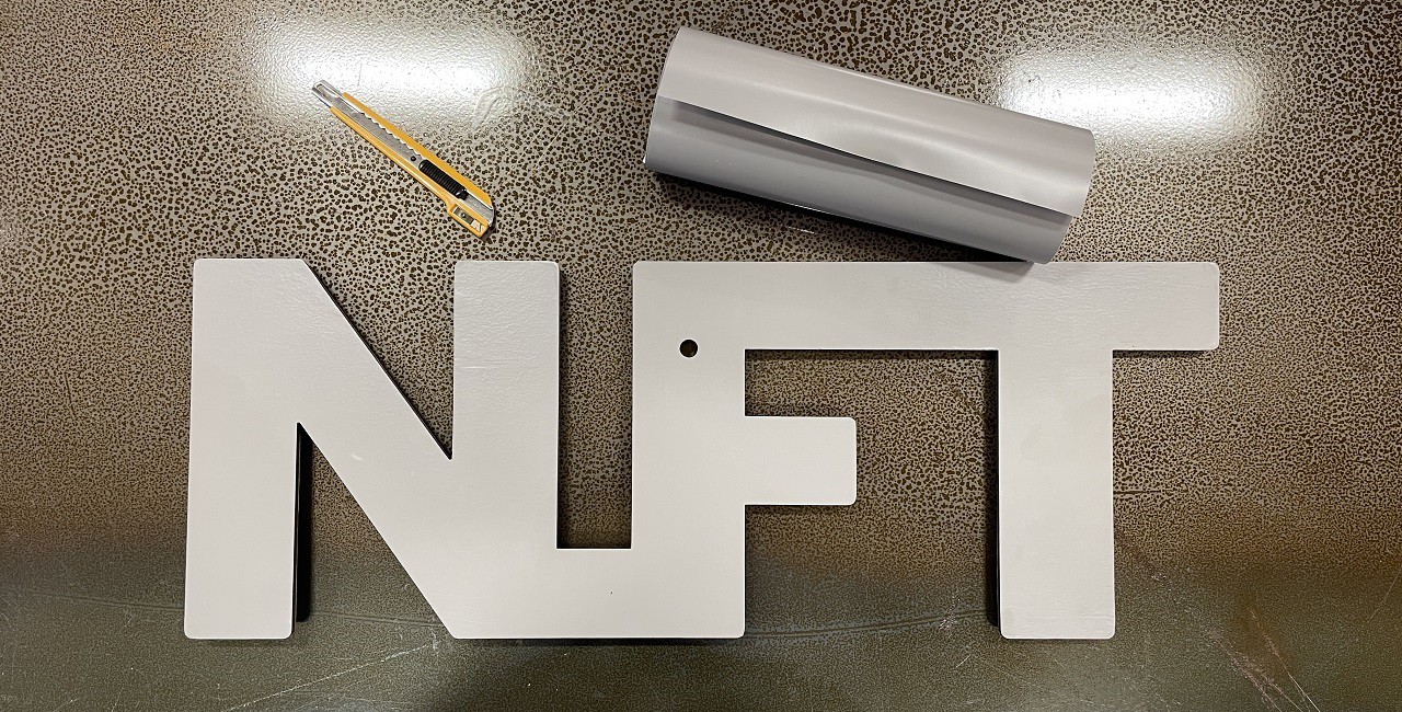
Put vinyl sheets to both sides of the lauan board.
![]()
-
6Screwing the base parts
TOOLS
- Awl
- Phillips Screwdriver
COMPONENTS
- Self-tapping screw M3x6 x10
Mark the 10 screw positions with an awl.
![]()
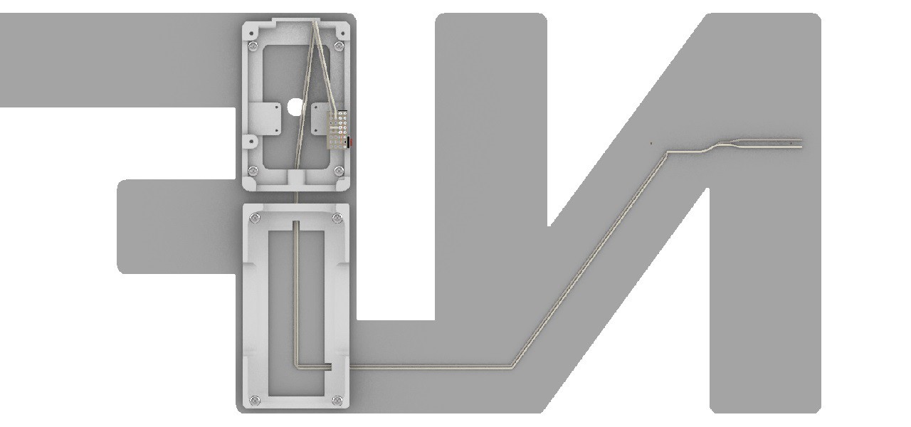
Screw the base parts to the board with 10 self-tapping screws M3x5.
![]()
The Raspberry Pi case and the power bank holder must be inside the board.
![]()
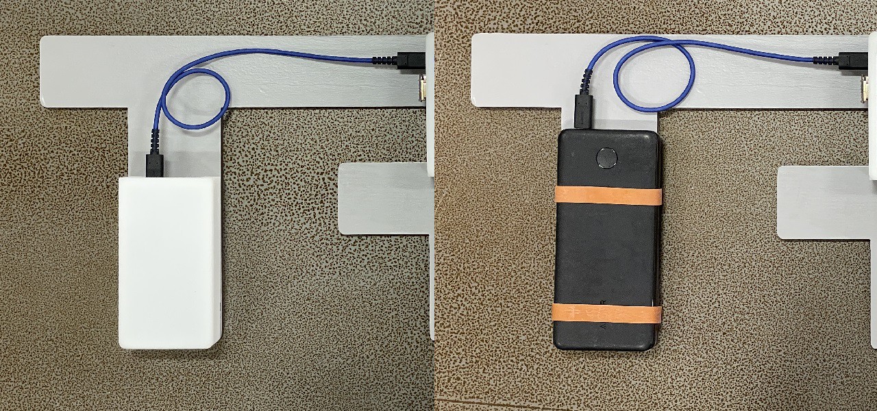
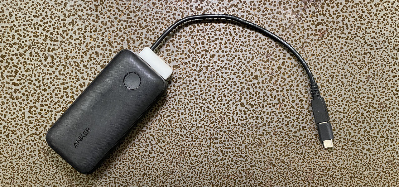
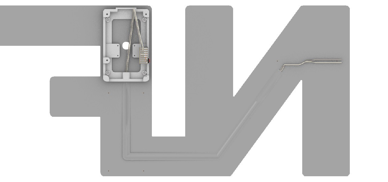
If you don't want to modify the USB Type-A connector of the power supply cable, screw the power bank holder to the left side. Modifying the USB Type-A connector is a relatively difficult task.
![]()
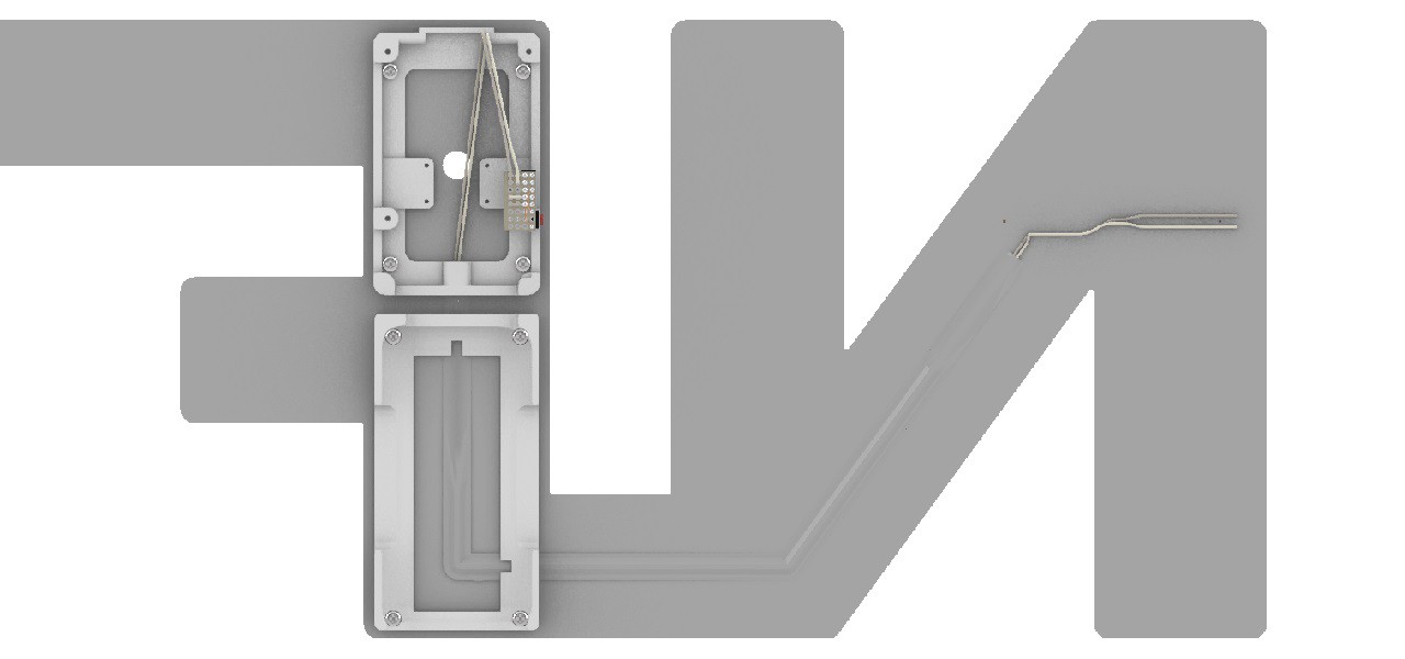
However, It is difficult to hold the T with a hand. There is also an idea that allow you to use various power banks without attaching a power bank holder.
![]()
-
7Modifying the USB Type-A connector of the power supply cable
TOOLS
- Nipper
- Wire Stripper
- Electrical Tester
- Tweezers
- Soldering Station
- Solder
- Phillips Screwdriver
- Kapton Tape
COMPONENTS
- Micro USB / USB Type-A Flat Cable 150mm PG-MUC01M07
- BUFFALO Conversion Adapter micro B to Type-C Black BSMPCADC100BK
- USB Female Type-A Connector
- Machine Screw M2x6 x2
If you chose not to modify the power supply cable in the screwing the base parts step, proceed to the next step.
Modify the power supply cable connector to a space-saving type. This step is difficult. It requires detailed work. And the cable sheath inside the power supply cable is prone to melting. Of course, never short-circuit the power supply cable.
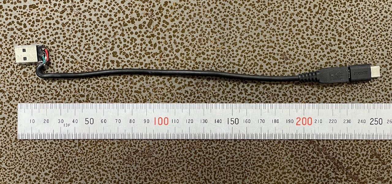
You may choose USB Cable Type-A to USB Type-C. Since I was initially using Raspberry Pi 3B for this project, I used a USB Cable Type-A to Type-B cable.
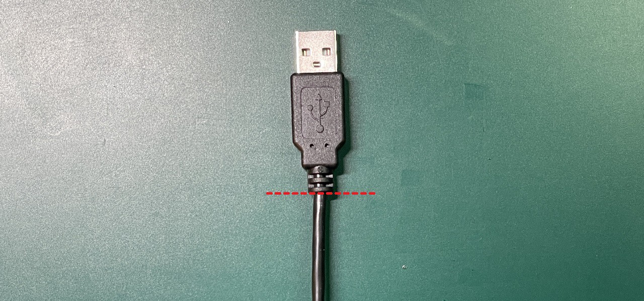
Cut off the USB Type-A connector of the power supply cable.
![]()
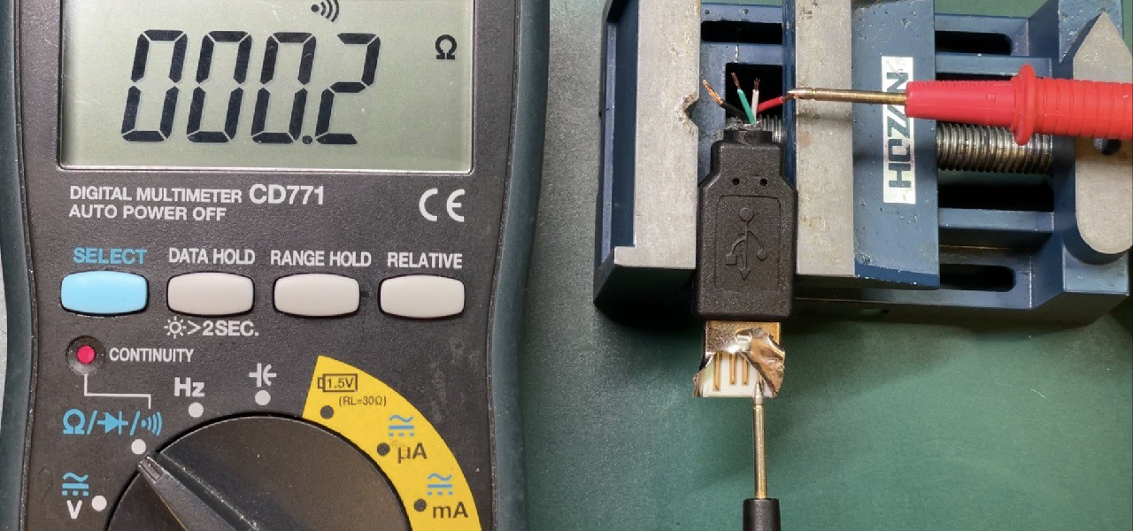
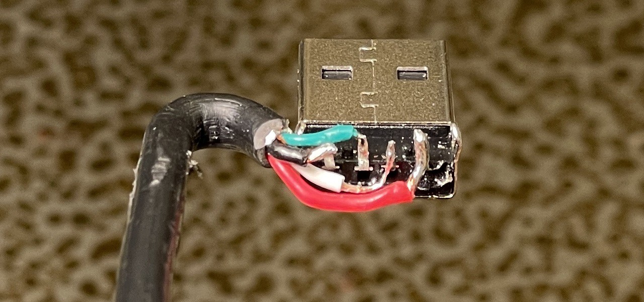
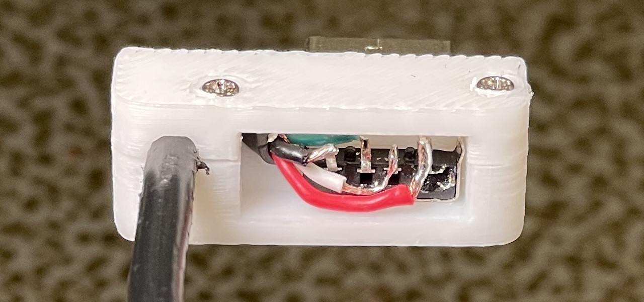
Check the cut-off USB Type-A connector and cable assignment with an electrical tester.
![]()
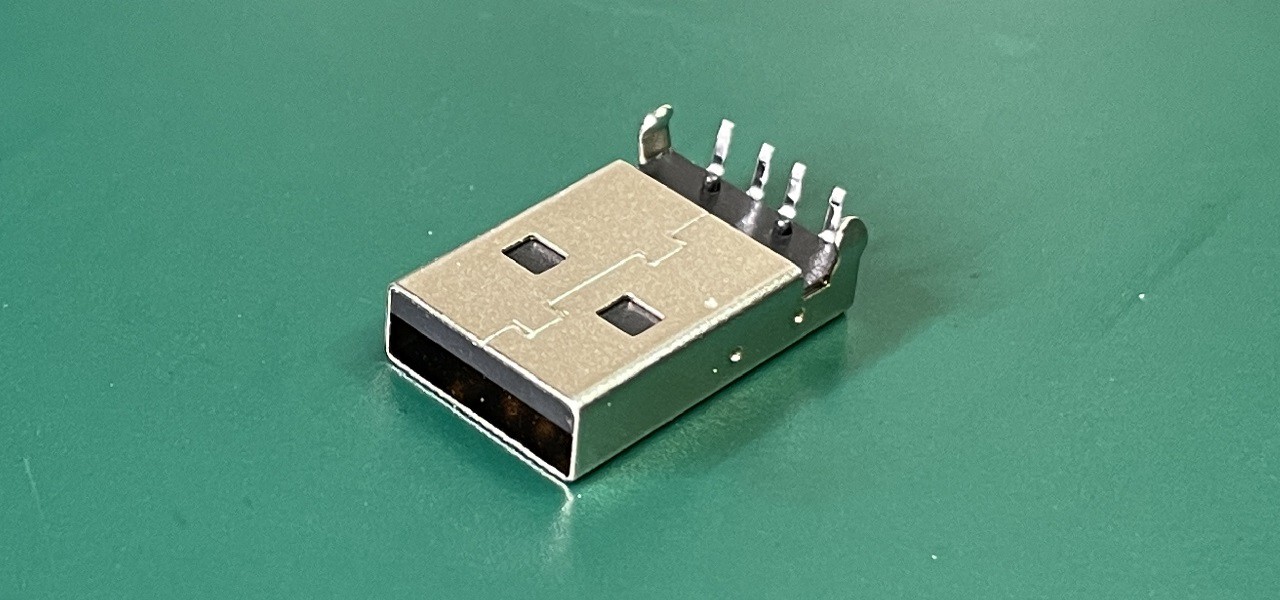
USB Female Type-A Connector
![]()
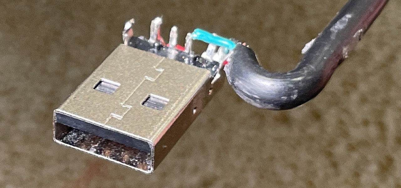
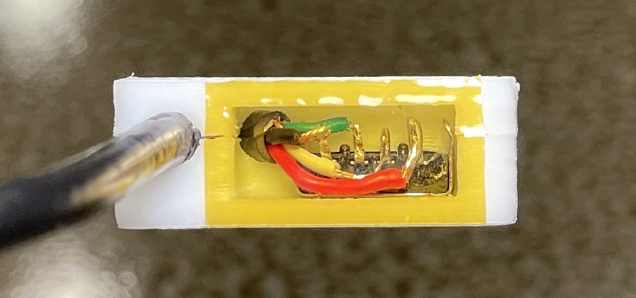
Solder the cable to the new USB Type-A connector with the same assignment you checked earlier
![]()
![]()
It is easy to connect the power supply cable to the Raspberry Pi if the USB Type-A connector and USB Type-B connector are not twisted around each other as shown in the image below.
![]()
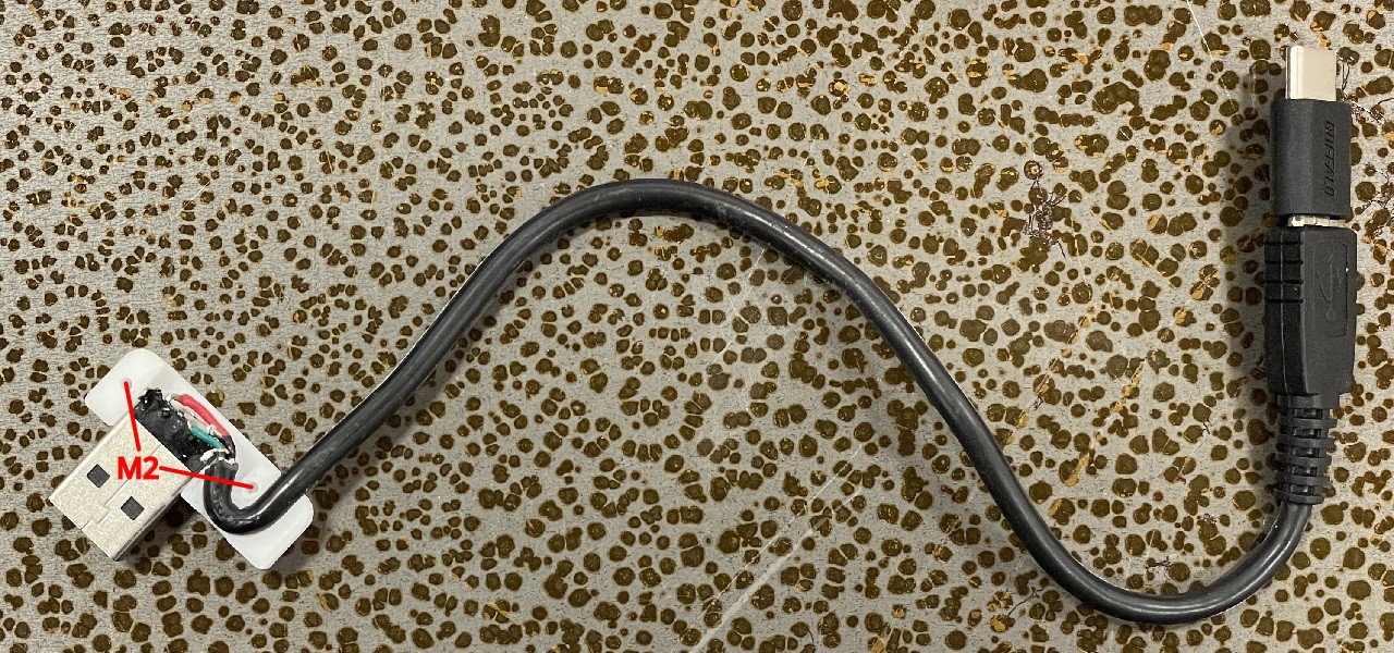
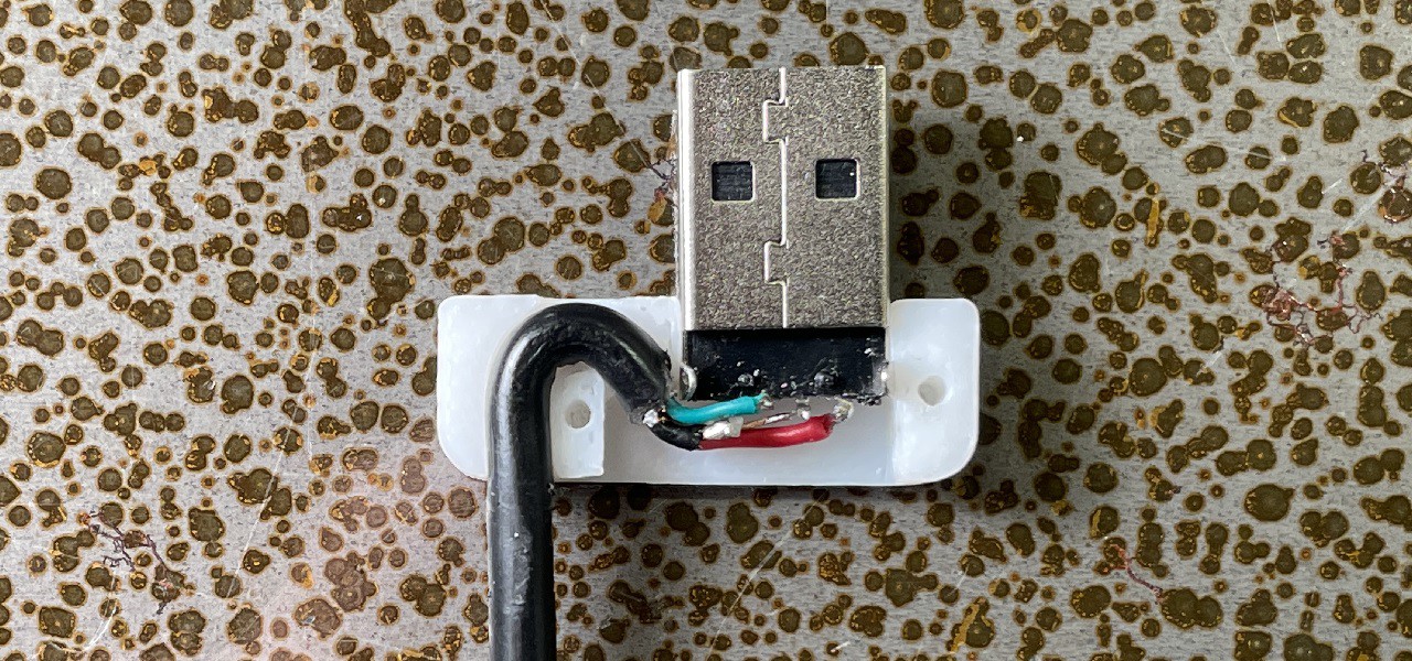
Sandwich the USB Type-A connector with the 3D printed parts. Then fix them with 2 machine screws M2x6.
![]()
![]()
Seal the hole with tape such as Kapton tape.
![]()
![]()
-
8Installing the camera, Raspberry Pi and touch screen
TOOLS
- Phillips screwdrivers
COMPONENTS
- Raspberry Pi Camera V2
- Adafruit Flat Flex Cables for Raspberry Pi Camera - 200mm
- OSOYOO Raspberry Pi Touch Screen 3.5"
- Machine Screw M2x4 x4
- Machine Screw M2.6x6 x4
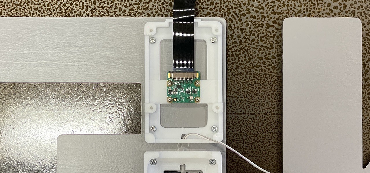
Secure the camera with 4 machine screws M2x4.
![]()
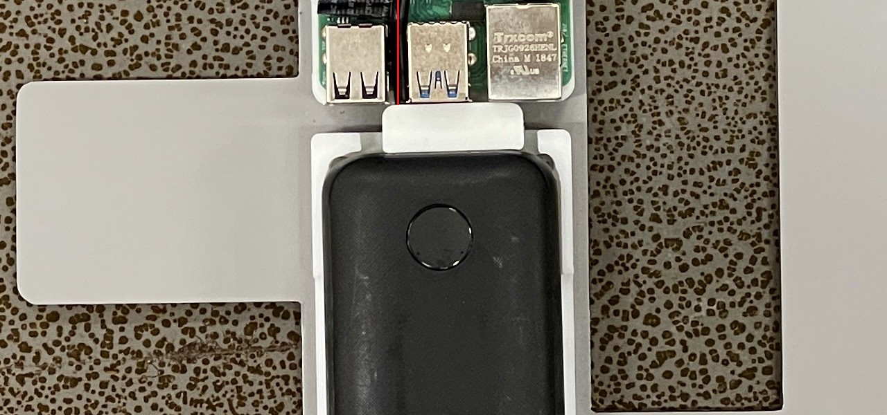
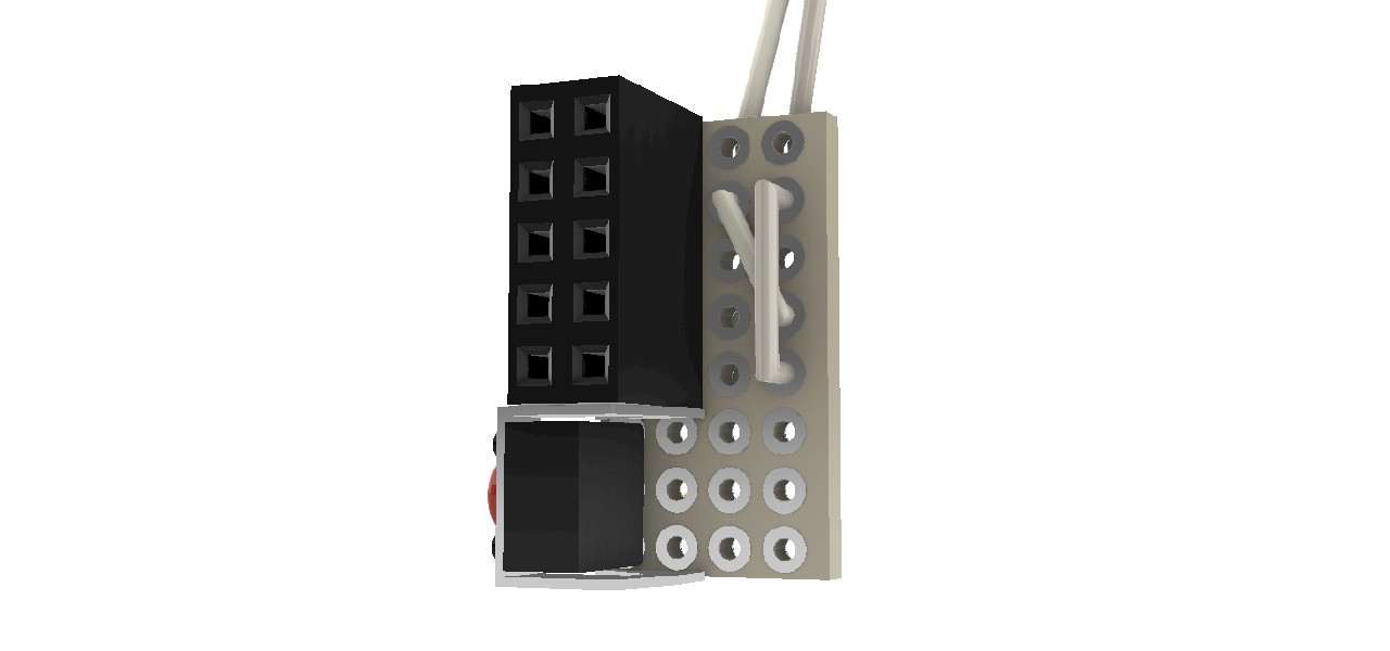
Secure the Raspberry Pi with 4 machine screws M2.6x6. Pass the power supply cable through the gap between the Raspberry Pi's USB ports.
![]()
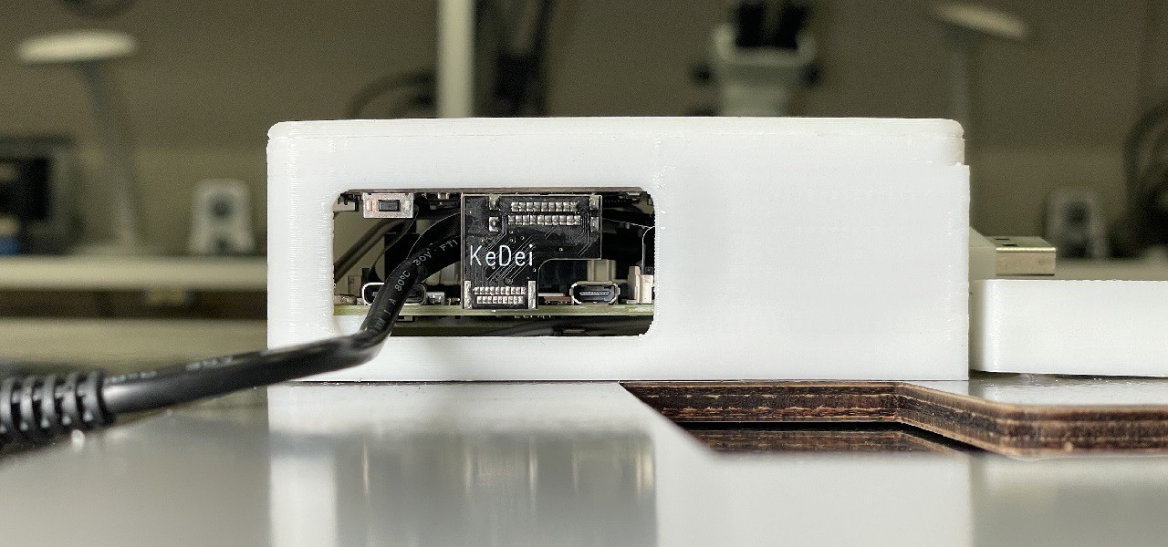
Attach a touch screen to the Raspberry Pi. At that time, bend the flat flex cable carefully so that it does not break.
![]()
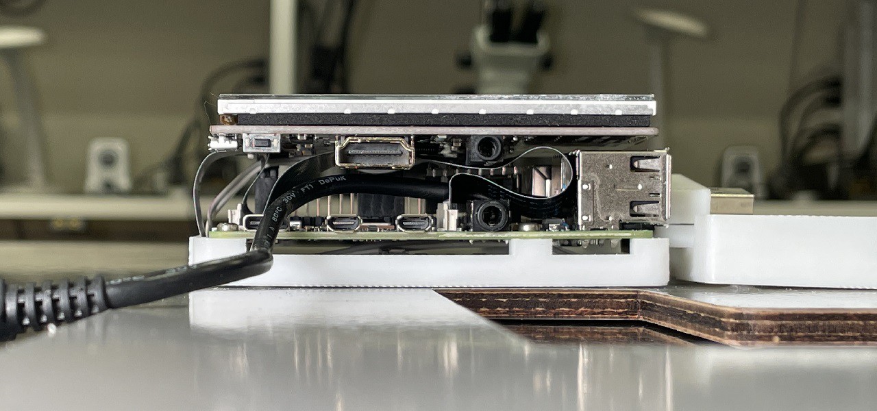
Put the cover on the Raspberry Pi. Attach the HDMI connector that connects the touch screen and the Raspberry Pi.
![]()
-
9Building the Raspberry Pi GPIO Connector and the shutdown button
TOOLS
- PCB Board Cutter
- Nipper
- Tweezers
- Soldering Station
- Solder
- Cutter Knife
COMPONENTS
- Universal Prototype Board 95x72mm 1.6mm thick
- TACT Switch SKHHLPA010
- Pin Socket 2x5 2.54mm Pitch
- 0.3mm Polyurethane Copper Wire 100mm
- 1mm 2 Pin Flat Capper Cable 550mm
- Vinyl Sheet 400x10mm 0.1mm thick
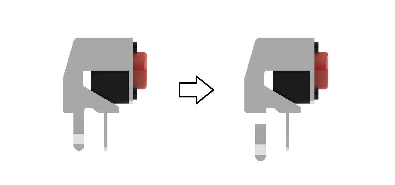
Cut parts of the metal of a tact switch in some way as shown below. This is hard, so be careful when choosing the tool to cut it.
![]()
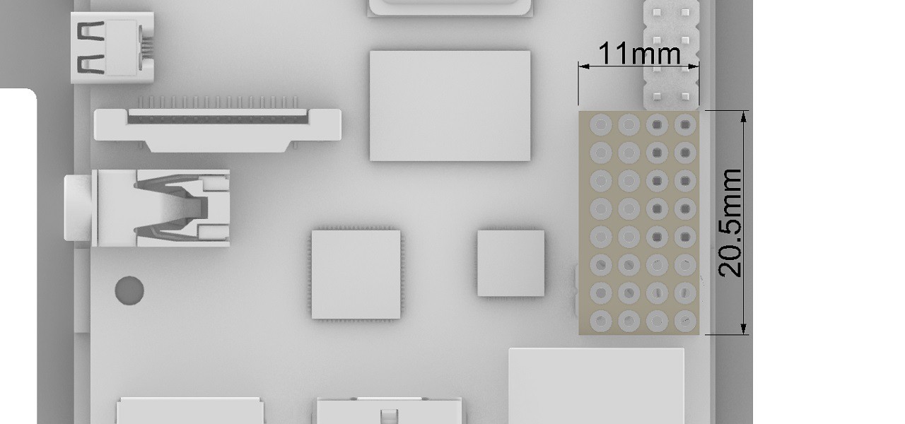
Cut an universal prototype board with the PCB board cutter as shown in the image.
![]()
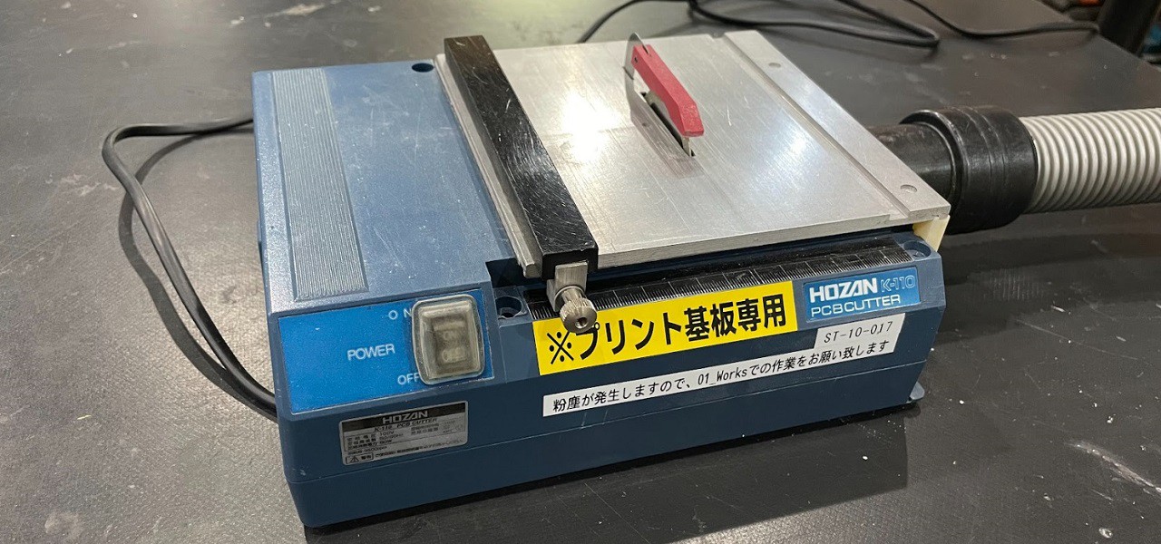
PCB Board Cutter
![]()
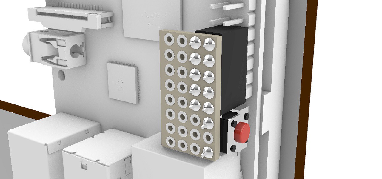
Solder a pin socket and a tact switch. At that time, it is necessary to widen the width of the pins of the tact switch a little.
![]()
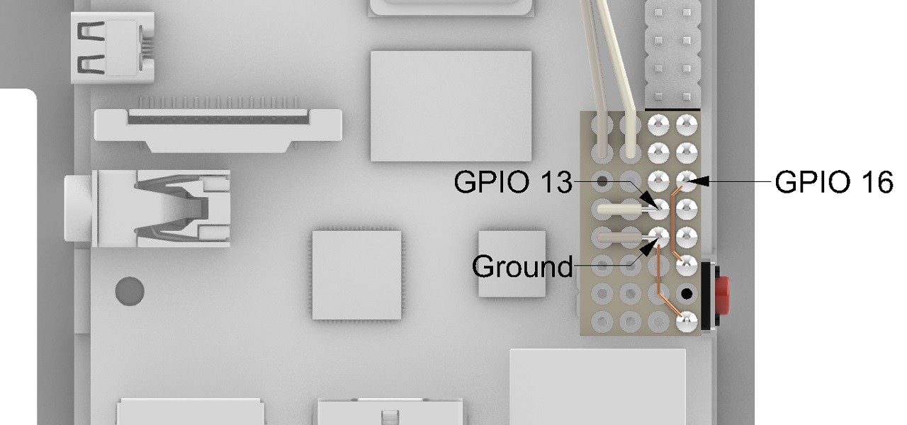
Solder the tact switch to the GPIO 16 and the Ground with polyurethane copper wires. Solder the 2 pin flat capper cable to the GPIO 13 and the Ground. Pass the 2 pin flat capper cable through the holes in the universal prototype board. This is to prevent the cable from being pulled and broken. If you can't get the cable through the holes, widen the holes with a pin vise.
![]()
![]()
Fix the 2 pin flat capper cable to the board with vinyl sheets.
![]()
![]()
![]()
-
10Installing the power bank
TOOLS
- Cutter Knife
COMPONENTS
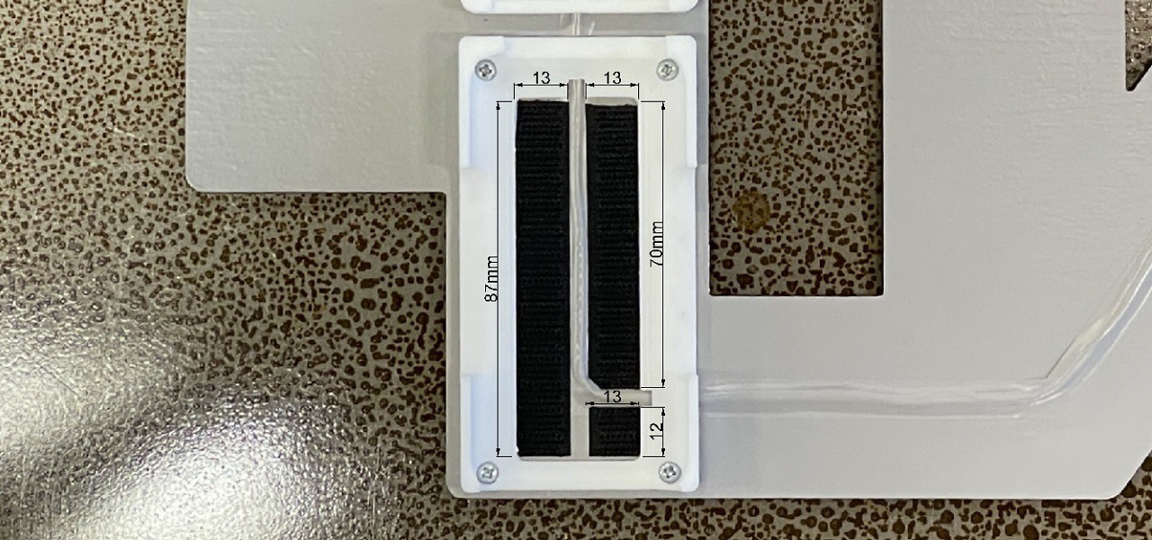
- Velcro Tape self-adhesive with hook tape 87 x 26mm 1.25mm thick
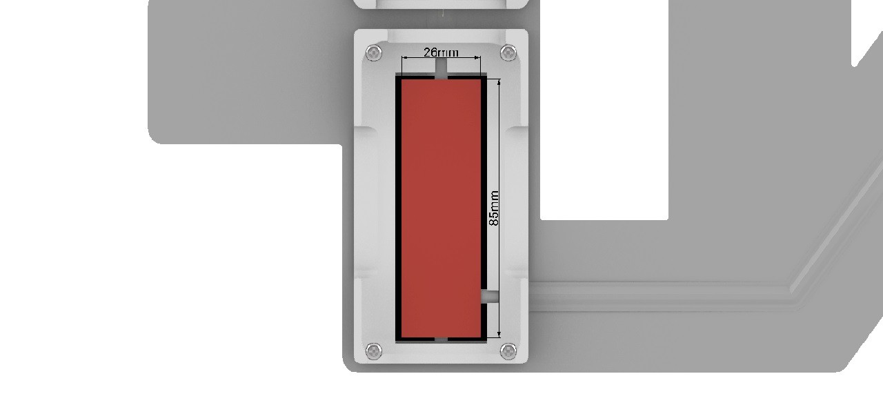
- Velcro Tape self-adhesive with loop tape 85 x 26mm 1.25mm thick
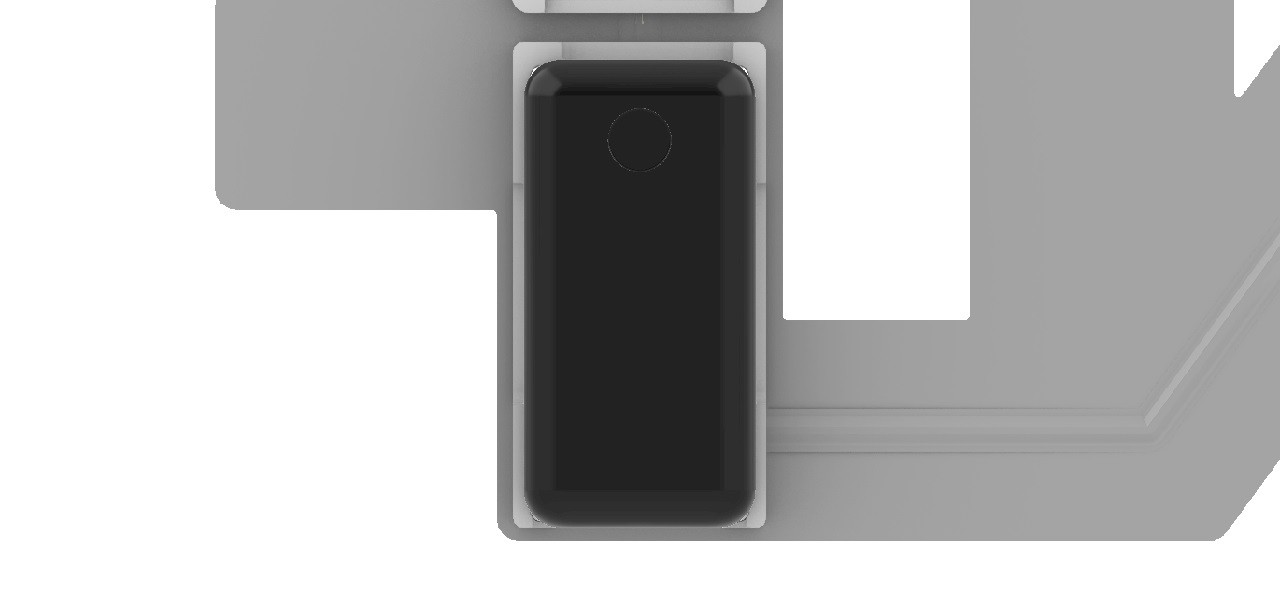
- Anker Power Core 10000 PD Redux (Power Bank)
Cut the Velcro hook tape and put it to the board.
![]()
Attach the Velcro loop tape to the Velcro hook tape and peel off the adhesive protection sheet. The Velcro loop tape in the image is red, but the actual color is black.
![]()
Insert the power bank into the holder.
![]()
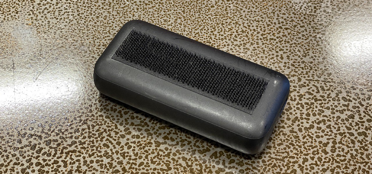
Velcro loop tape is attached to the power bank.
![]()
Blockchain Camera
A photo taken with this camera will instantly become a NFT. This camera aims to prove with blockchain that a photo was taken with a camera.


Discussions
Become a Hackaday.io Member
Create an account to leave a comment. Already have an account? Log In.