agp.cooper
-
Simulating the BJT Mixer
01/04/2017 at 04:04 • 2 commentsSimulating the BJT Mixer
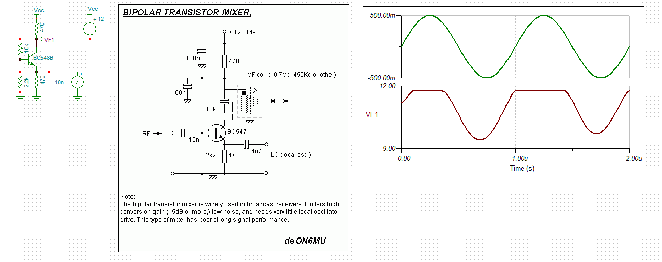
After searching the Internet I did find a few circuits with component values and local oscillator power requirements that allowed me to digitise a schematic in order to look at the simulation:
![]() (source: http://users.belgacom.net/hamradio/schemas/mixer1.gif)
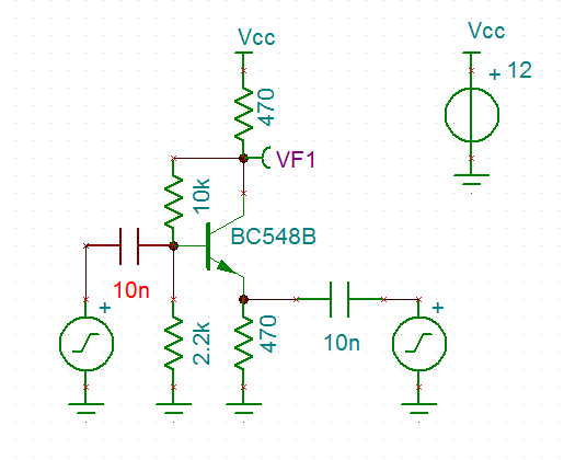
(source: http://users.belgacom.net/hamradio/schemas/mixer1.gif)Here is my initial simulation:
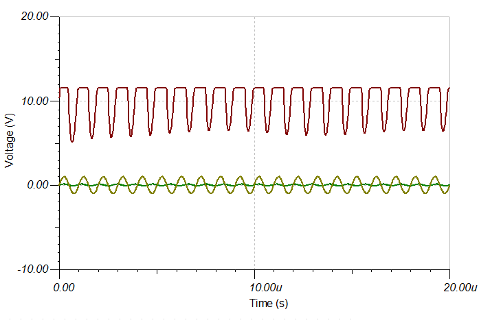
Okay it is pretty clear that it is a Class B amplifier (an important observation!).![]()
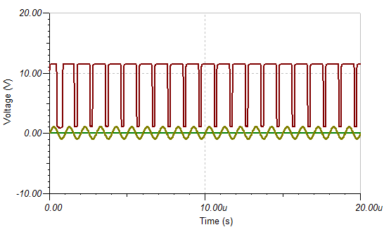
Next lets mix in the signal:
![]()
And what did I get:
![]()
Now this is not right! Even with a uV signal?
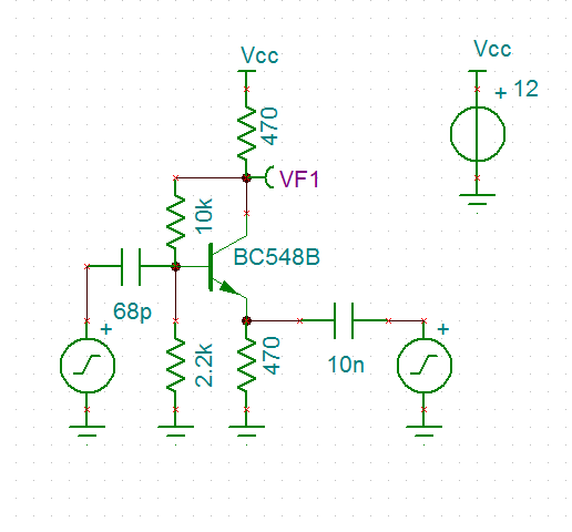
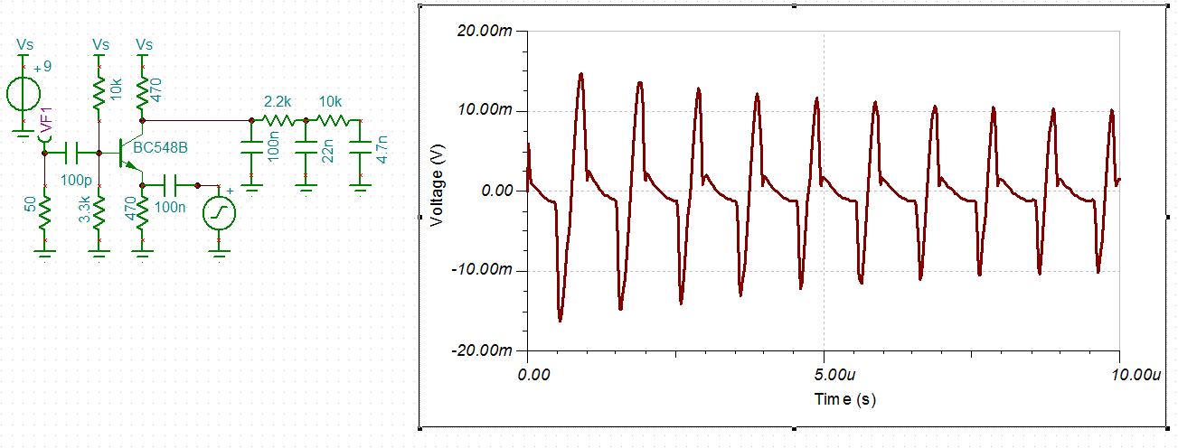
Okay reduce the coupling capacitor:
![]()
And now it works (all that is required is a low pass filter to extract the 100 kHz signal).:
![]()
Need to look at the range of couple capacitors values that work.
The above local oscillator (LO) is 1 MHz and 2v pp and the signal is 1.1 MHz and 200 mv pp. Getting a 50% duty (i.e. Class B operation) for the mixer requires adjustment of the LO amplitude or the bias resistors.
Conclusion
Well I am happy I now know how this mixer works. It is a switching mixer) configured as a Class B amplifier. It is now easy for me to design and to tweak.
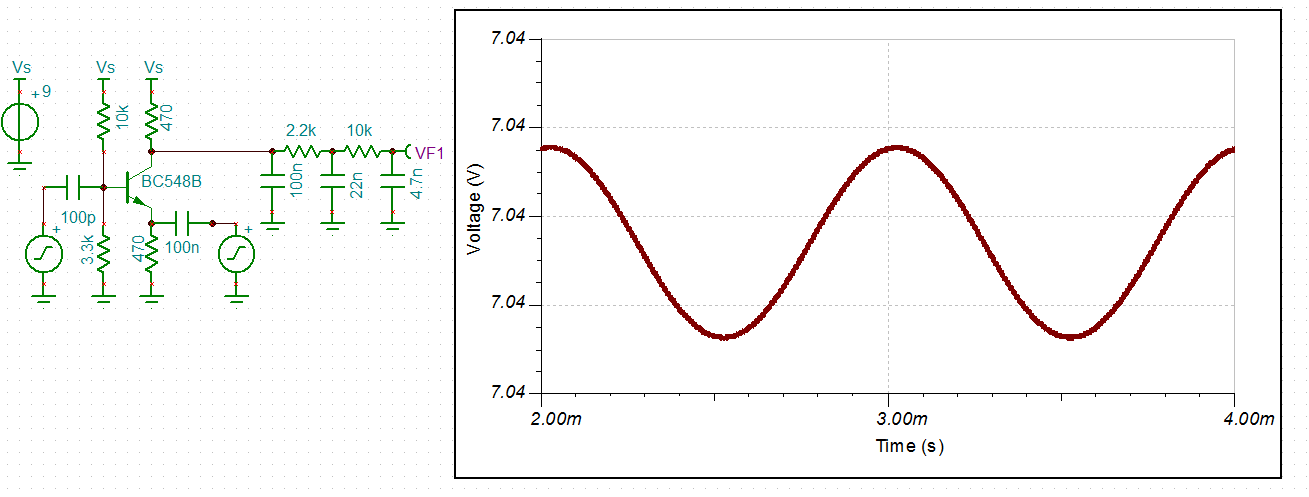
Recovering Audio
![]()
The modulated RF is 2 mv pp and the recovered audio is 1 mv pp. The line thickness is due to left over RF. Pretty happy with that.
Port Isolation
How much is the LO isolated from the input? Practically nothing gets through:
![]()
That is 20 mv pp from a LO of 1.4 v pp.
Regards AlanX
The Bipolar Junction Transistor RF Mixer
The Bipolar Junction Transistor (BJT) is your garden variety transistor. This project tries to workout how to design a BJT mixer.
 (source: