 Mark Austin
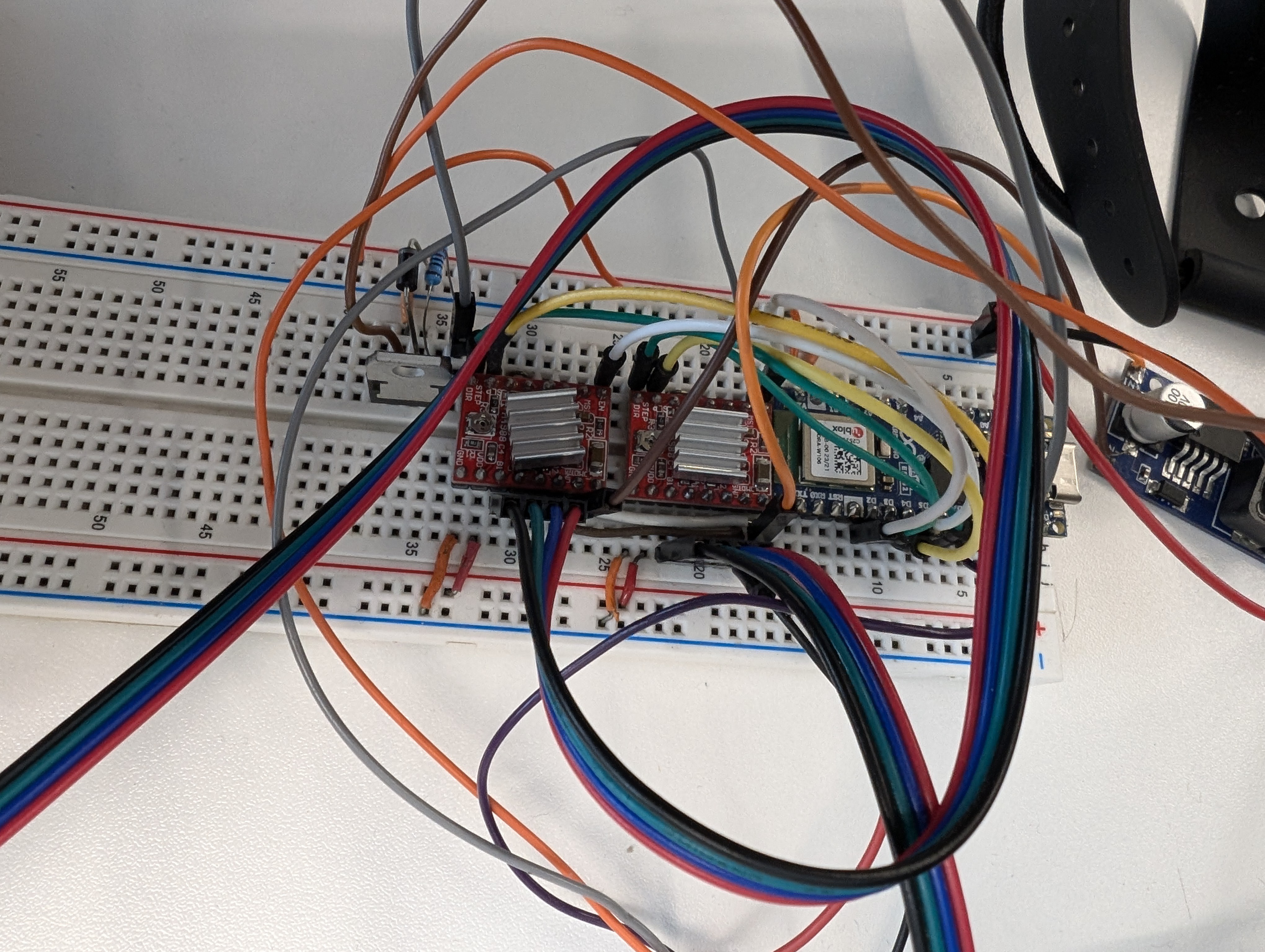
Up until now, we’ve been running motor control, chess piece detection, and electromagnet control through a breadboard. While this worked brilliantly for quick fixes and prototyping, now that we know all the electronic components needed for Gambit, it’s time to move away from the breadboard.
Why Move to PCBs?
One of the biggest issues with breadboards is their unreliable connections—cables can easily come loose if the board shifts. This was fine during prototyping, but now that our circuit is finalised, it’s no longer acceptable.
Component List
Power Input & Electromagnet Control
- 1x Buck Converter – Allows us to use a single power source, safely splitting power between the motors (12V) and the Arduino (5V).
- 1x Arduino Nano ESP32
- 2x Nema 17 Stepper Motors – Moves the electromagnet.
- 2x A4988 Motor Driver Chips – Controls the stepper motors.
- 1x Limit Switch – Calibrates the movement mechanism.
- 4x NPN Transistors – Acts as a digital switch for the electromagnets.
- 4x Rectifier Diodes – Stabilizes current from the electromagnets.
- 4x 240Ω Resistors – For digital signals from the ESP32.
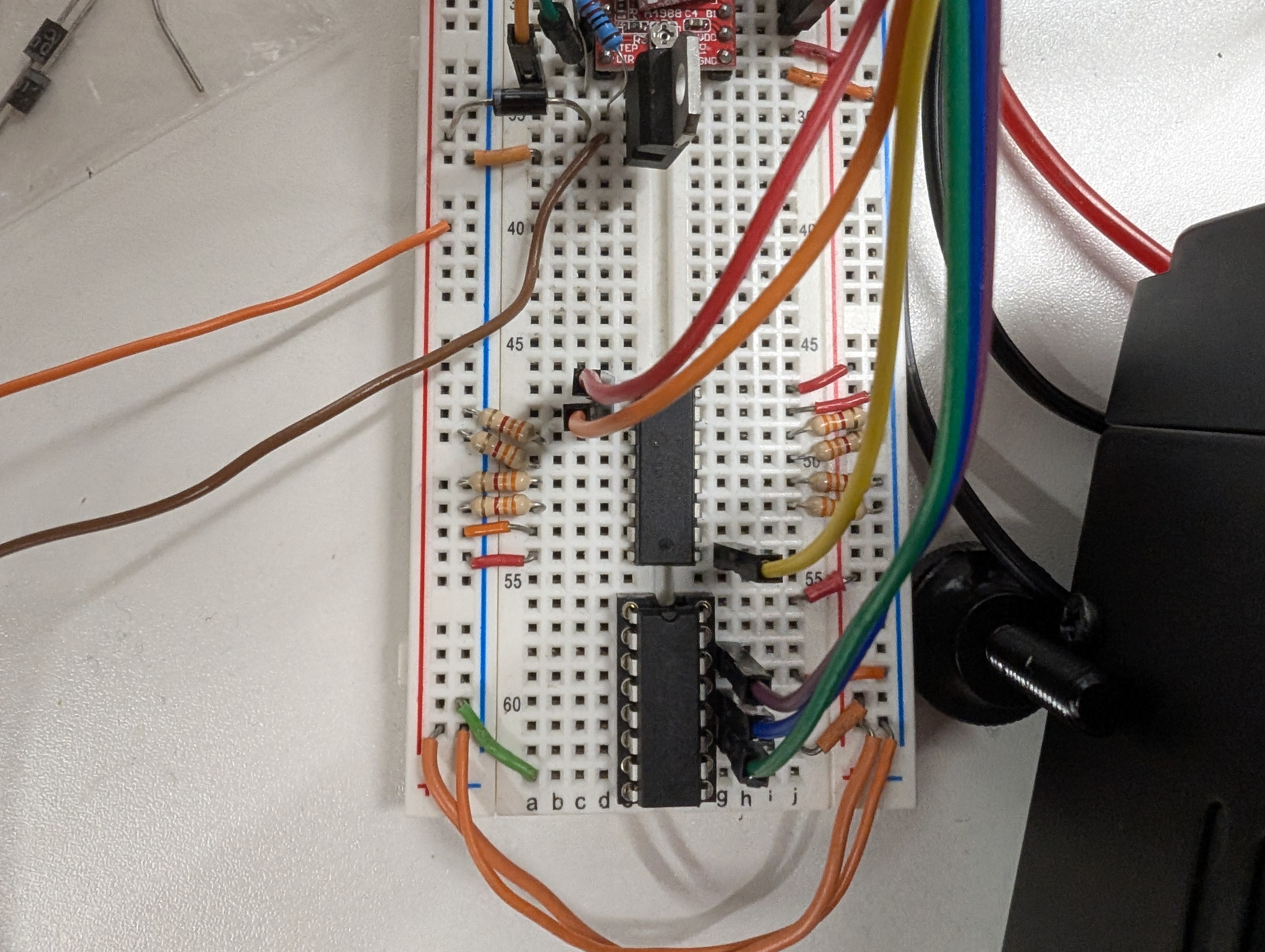
Chess Piece Detection
- 1x 74HC165N (Shift-In Register) – Reads the board’s columns.
- 8x 3.3kΩ Pull-Down Resistors – Stabilizes shift-in readings.
- 1x 74HC595N (Shift-Out Register) – Controls row activation (see our Detection Matrix blog).
Designing the PCBs
With the breadboard limitations in mind, I fired up Fusion 360 and designed two PCBs:
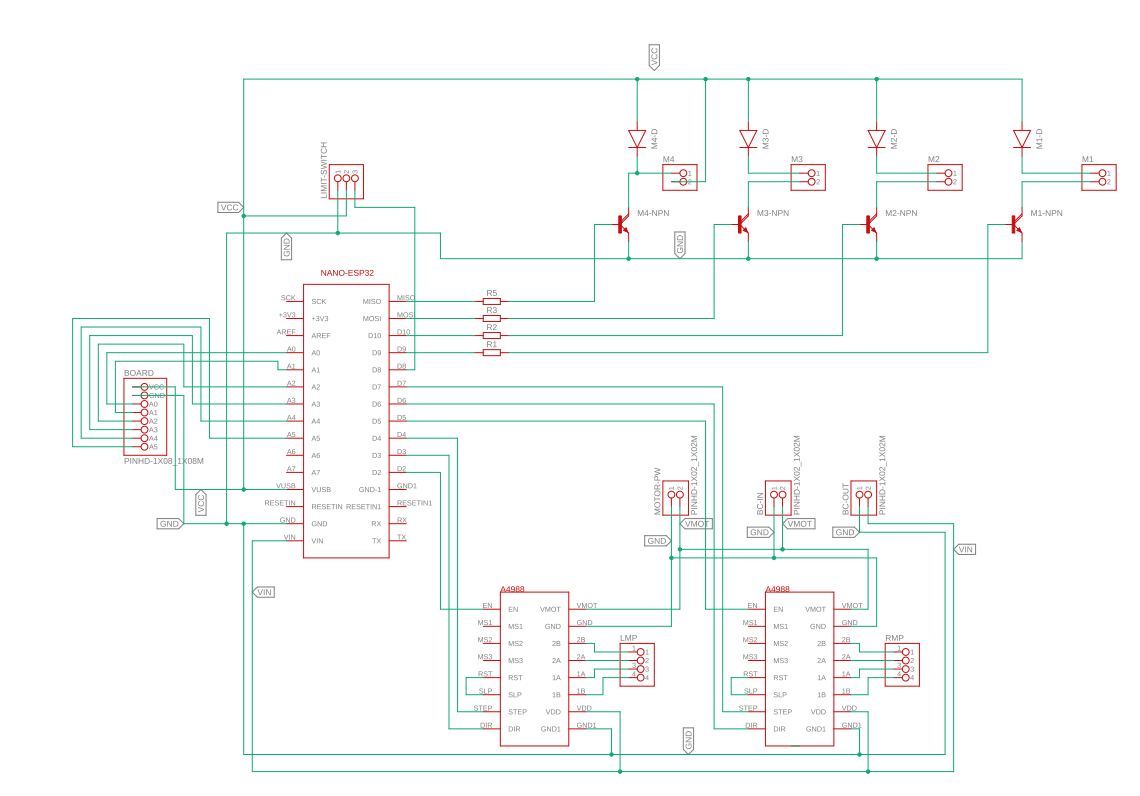
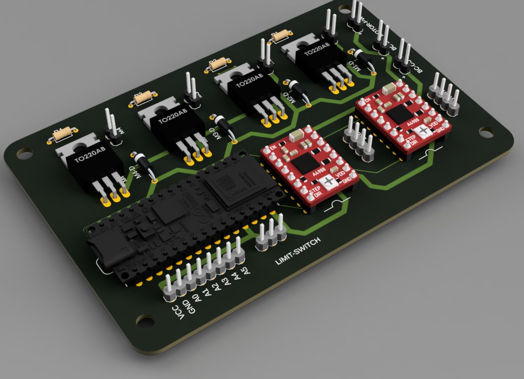
1. Motor & Electromagnet Control PCB
2. Detection Matrix PCB
After finalizing the schematics, we sent the designs to JLCPCB, and within a week, the PCBs arrived. We were really impressed with how quickly they were fabricated!
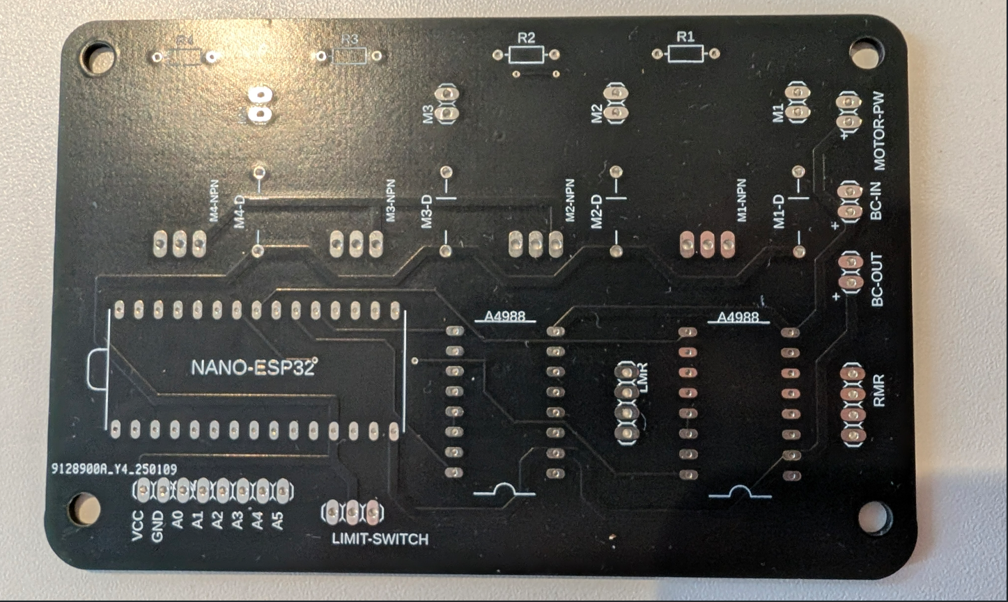
Motor & Magnet Control PCB:
Schematic
Render
PCB
Detection Matrix PCB:
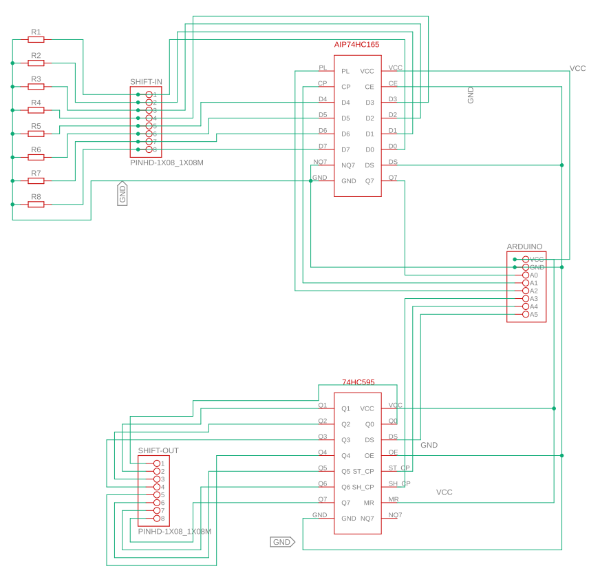
Schematic
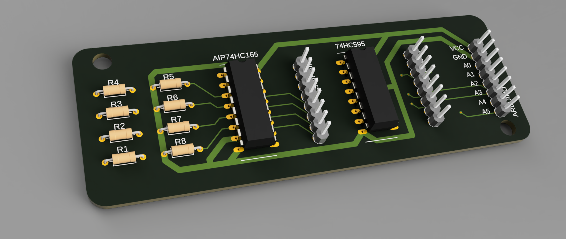
Render
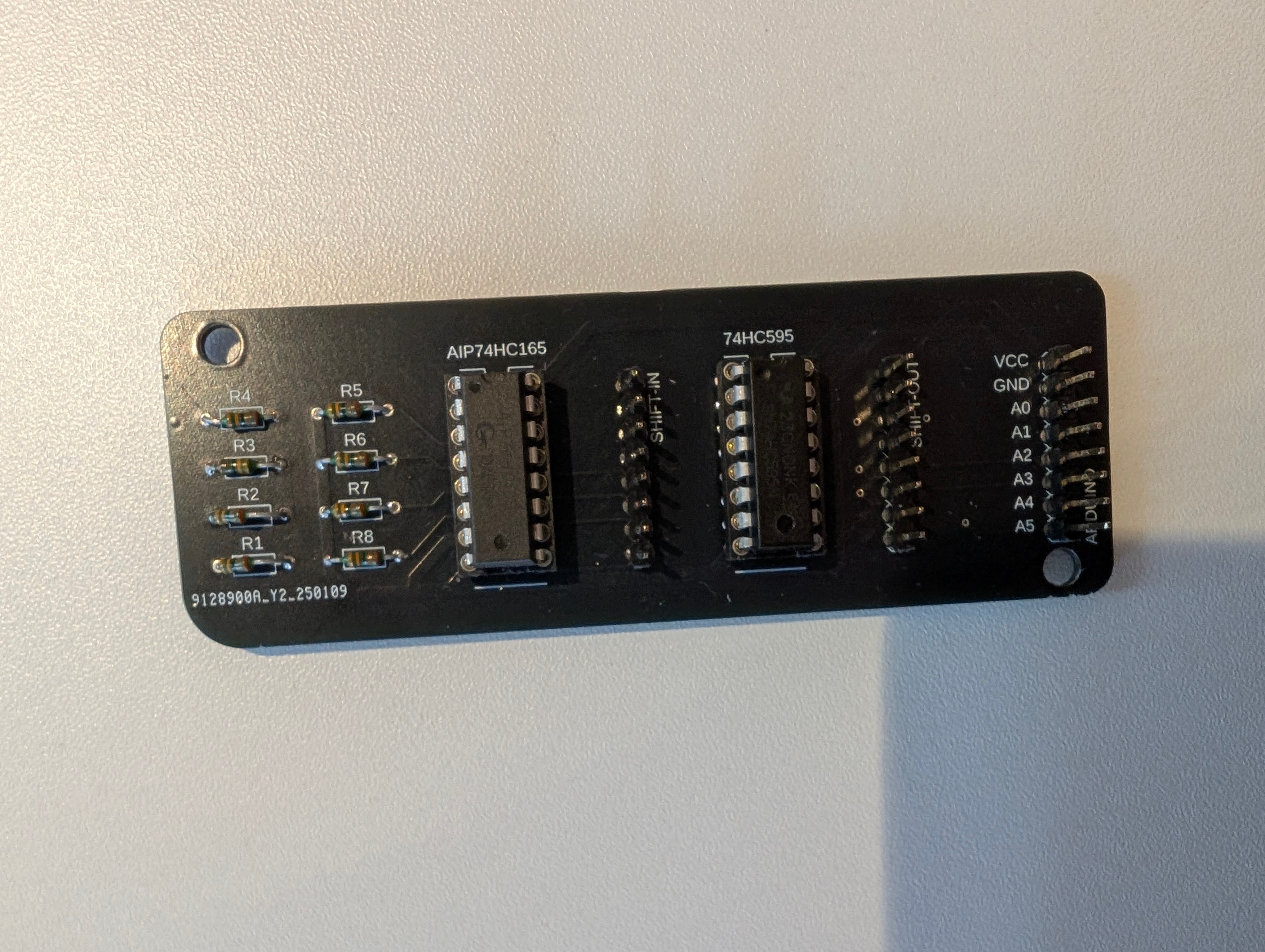
PCB
The Not-So-Good News
Unfortunately, this is where our excitement ended.
- Motor-Magnet-Limit Switch PCB Issue:
I mistakenly used incorrect drill sizes for the Arduino and A4988 chips, making the holes too small. As a result, we couldn’t mount the chips to test the circuit.
- Detection Matrix PCB Issue:
After soldering all the components—chips, pin headers, and resistors—we ran into unexpected behaviour. The circuit would only work if we held our finger under certain pins (PL, CP, and CE). This issue never occurred with the breadboard version, so we’re currently investigating the cause. So far, we’ve narrowed it down to parasitic capacitance.
Discussions
Become a Hackaday.io Member
Create an account to leave a comment. Already have an account? Log In.