-
From Renderings to Reality
09/10/2023 at 21:30 • 0 commentsThe prior logs relied heavily on renderings and your imagination. That's because a few key parts were still out for assembly. Well, they've finally arrived. So to the lab I go to built the first prototypes!
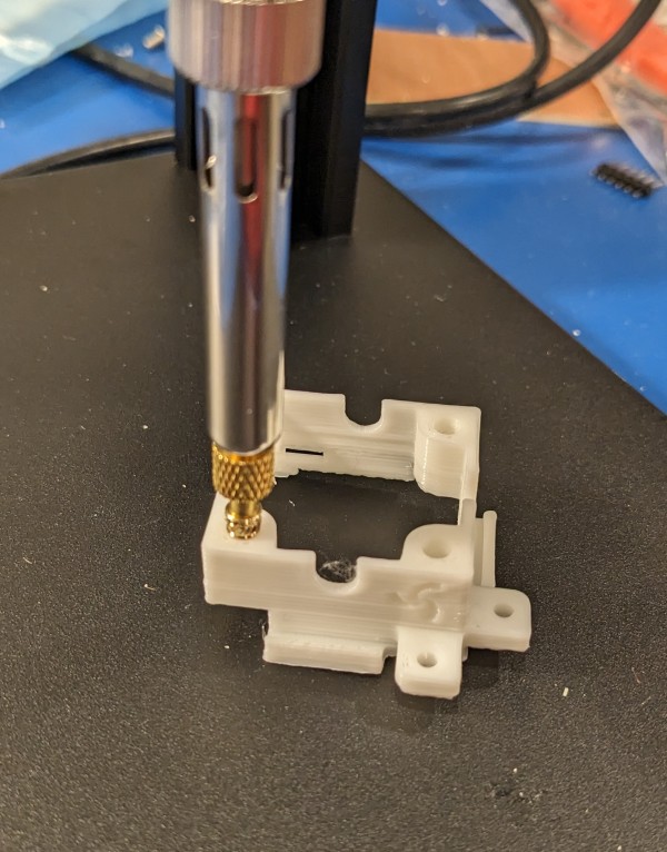
First things first. I still have to finish up the 3D printed frames from the last log. They have been waiting for heat set inserts to be installed. I held off on it because I was waiting on a press and special soldering iron tips. They've arrived as well, so here goes.
![]()
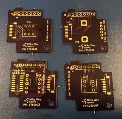
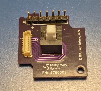
Next up are the PCBs. I've designed four types so far and had them fabricated through OSHPARK. The PCBs are for the following parts: DPDT pushbutton switch, DPDT toggle switch, dual gang potentiometer, and a 7-segment display with a driver.
![]()
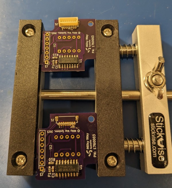
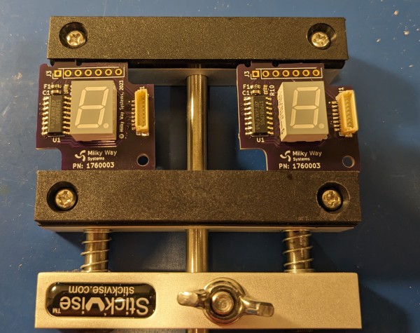
I assembled the pushbutton and display PCBs for now, since I have front covers to go with those ones.
![]()
![]()
![]()
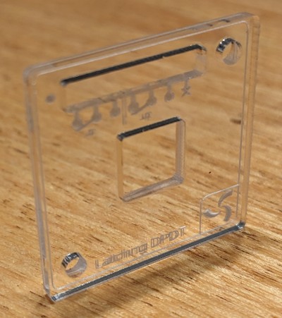
The final component is the top cover. They're fabricated with laser cut and engraved acrylic. So far I only ordered ones for the pushbutton and 7-segment display blocks. This is the one for the pushbutton Command Module block. The button cap will extend through the square hole at the center.
The cuts came out well, though the engraved text is difficult to read. It's too small for one thing, but also looks to be double-printed. I'll have to look into it further, but for now I'll forge forward with building the first prototypes.
![]()
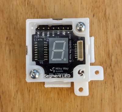
Okay, it's assembly time! This is of course the 7-segment display block. The PCB fit very tightly into the frame, but otherwise the assembly went smoothly.
![]()
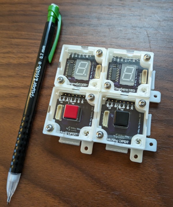
Next up are the pushbutton blocks. I built a pair of them as well. They have snap on caps that come in a few different colors. I attached all four together to check for fit. All seemed good.
![]()
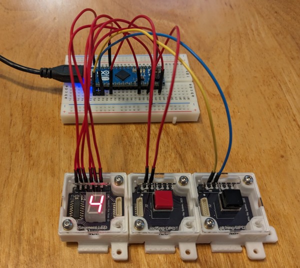
Finally, I connected a few blocks to a breadboard for testing. I wanted to test the display in particular because it uses a chip I have not used before. To do so, I connected it up to an Arduino's SPI interface and wrote some simple code to talk to the driver chip.
It worked! I was able to display 0-9 and the decimal point. The display brightness looked good - it was bright enough to read well in indoor lighting, but still comfortable to look at.
There are a few other features I'll have to test in the future. One interesting feature is that it is compatible with both 3.3V and 5V systems, and the brightness should remain the same across both (constant current drive). Additionally, the displays can be cascaded to add additional digits using a single SPI interface.
![]()
Alright, that's it for now! The first set of prototypes are built and under test. They'll need some refinement for sure, but its a good start.
-
PCB Design
09/05/2023 at 14:40 • 0 commentsIn the last post we talked about the command module block (CMB) frame design. Next up are the PCBs. Each CMB has a single PCB mounted on the bottom of the frame. It holds a user interface element such as a switch or potentiometer, along with a pin header and a small connector for interfacing to the outside world. You can see the PCB at the bottom of the exploded view.

This particular PCB holds a pushbutton switch. When assembled, the switch's button cap protrudes through the square opening in the top cover. The pin header will line up with the slot in the cover to provide access for installing jumper cables.

I've also designed a few others to have a nice assortment of UI elements:
- Pushbutton PCB - Holds a DPDT pushbutton switch with removable button caps (red, white, or black). The switch is available in momentary and latching versions.
- Toggle PCB - Holds a mini DPDP toggle switch. Great for retro stuff and general prototyping.
- Dual Gang Potentiometer PCB - Holds a dual-gang potentiometer. Great for analog circuit prototyping and for general knob based control.
- Seven Segment Display PCB - Holds a 7-segment LED display with a shift register based driver. These can be cascaded to form larger displays. General purpose retro-ish display.
All of the PCBs being fabricated. For now, here are some nice renders from KiCad.


-
Frames hot of the press!
09/02/2023 at 18:09 • 0 commentsAt the core of a command module block (CMB) is a part that I call the frame. It holds everything together and allows the CMBs to attach to each other. The frame is sized to fit a variety of elements, such as switches and potentiometers, but is no larger than it needs to be. It also provides mounting features for a circuit board on the bottom and a cover on the top side.
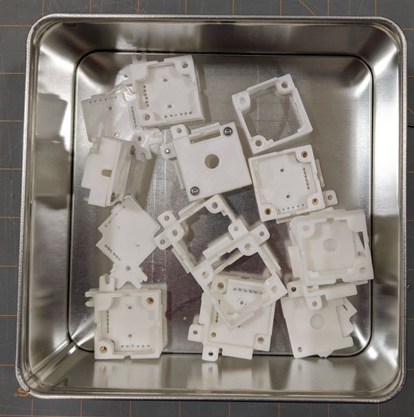
I thought the frame would be an easy design . . . then many iterations later, realized that it's quite tricky to get right. In fact I've accumulated a whole bin full of past designs that didn't quite work for one reason or another!![]()
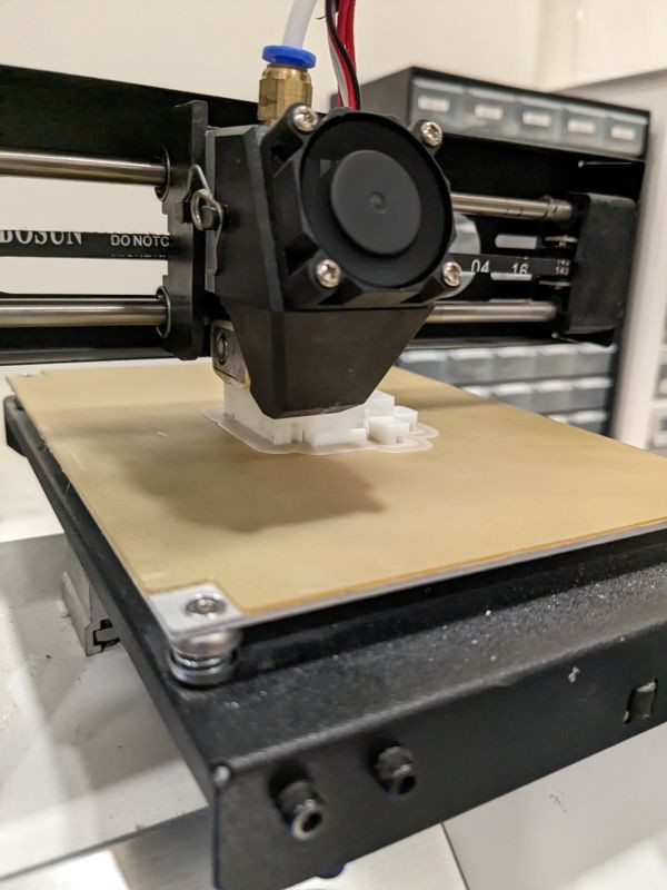
But behold, the latest version! I think it's pretty promising, but has lots of testing ahead of it. I've been churning some out over the past couple days.
![]()
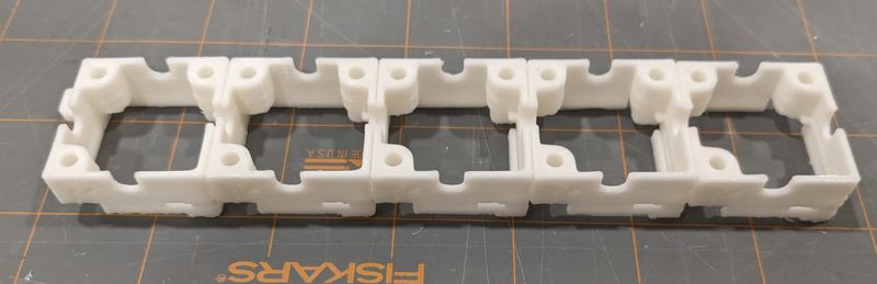
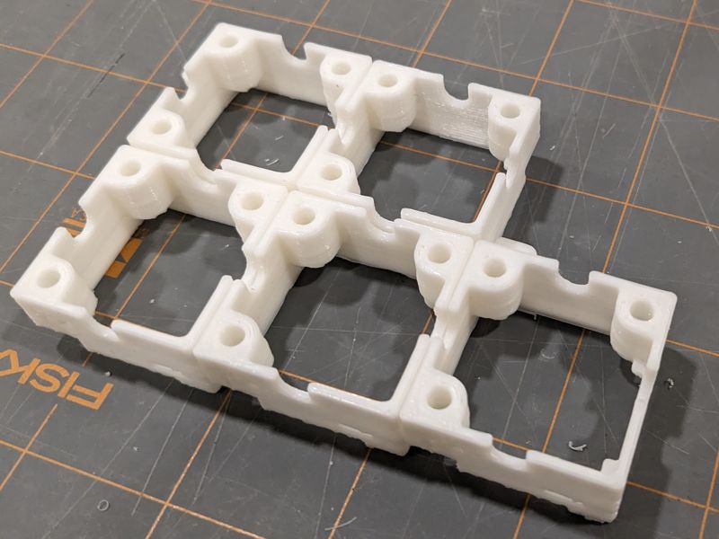
The frames connect together in rows or grids. After printing several, I was able to test their fit.
![]()
![]()
So far so good! They fit together just fine.
The next step will be installing heat set inserts. The inserts provide mounting points for the circuit board and top cover. They also allow you to more permanently fasten two CMBs together using a single screw.
If all continues as planned in the coming couple weeks, I'll install the circuit boards and front covers. They're being fabricated as you're reading this.