 Richard Testardi
-
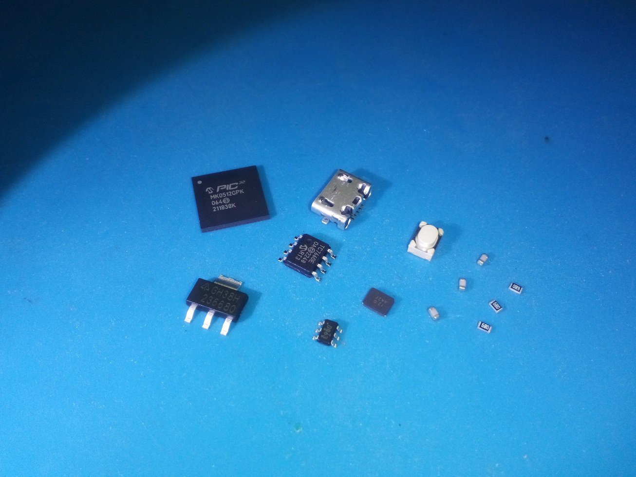
1Supplies
Inside "scope.gerber.27.zip", attached, is a bill of materials; alternately, you can get the bill of materials directly from mouser.com using this link: https://www.mouser.com/ProjectManager/ProjectDetail.aspx?AccessID=dad3ac0035
You can get all the parts from mouser, or you can get the MCUs a bit cheaper from Microchip Direct.
The "PIC32MK0512GPK064-I/MR" MCU part is brand new. If you have trouble finding it, you can use the "GPK" (general purpose) or "MCM" (motor control) flavor, with identical firmware, and you can also use the "1024" (1024kB) or "0512" (512kB) flash size as well. I find the PIC32MK MCU in its default QFN package with "/MR" suffix (much!) easier to use than the QFP with "/PT" suffix, but the gerbers can also be modified in minutes to use a QFP instead of a QFN -- all traces are laid out for the larger part already.
![]()
-
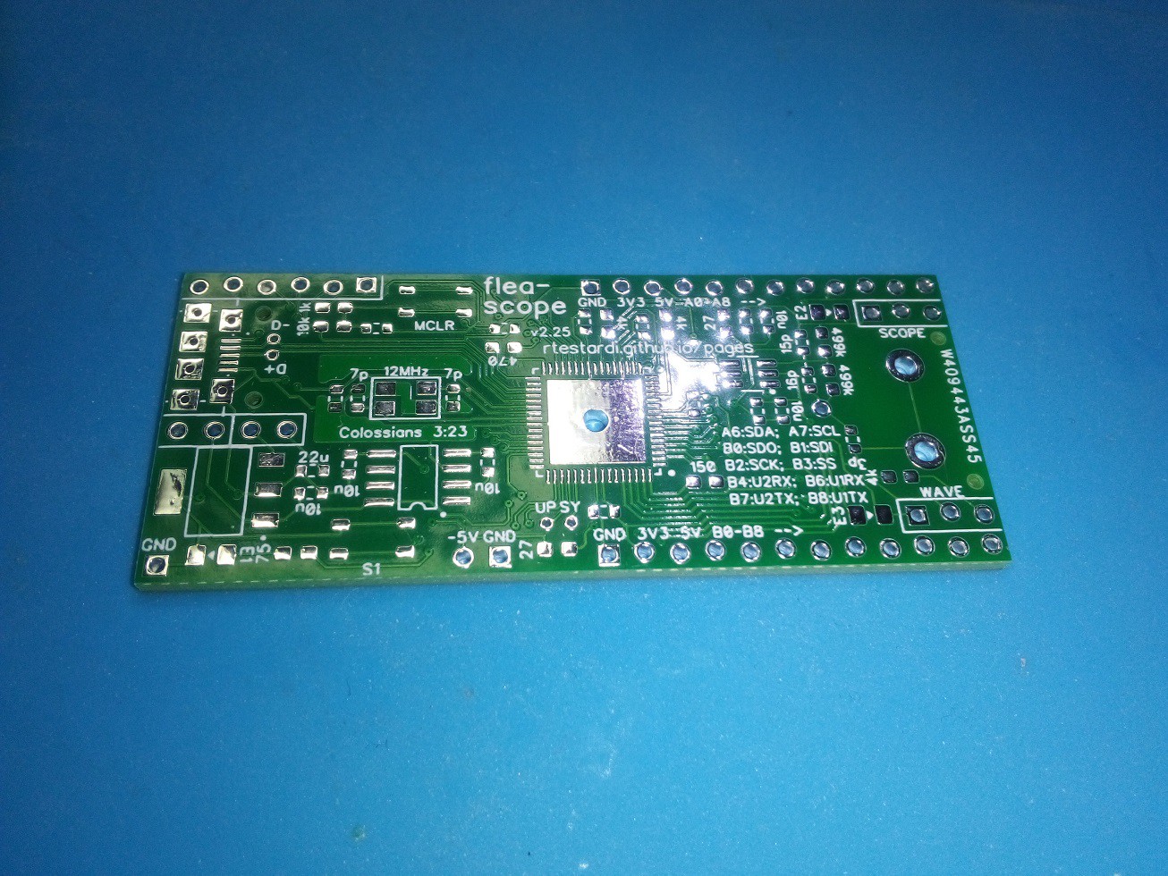
2Order the PCB
"scope.gerber.27.zip", attached, contains all the gerber, etc., files you will need to build the Flea-Scope printed circuit board (PCB). You can just upload this zip file to a place like pcbway.com and have them fabricate empty PCBs for you in a week or so.
As a side note, I have had great experiences with pcbway.com for both boards and non-framework stencils. When using their website, be sure to click on "Quick-order PCB", so you can upload the zip file containing the gerbers, etc., first, and not have to manually enter any parameters like board dimensions.
![]()
-
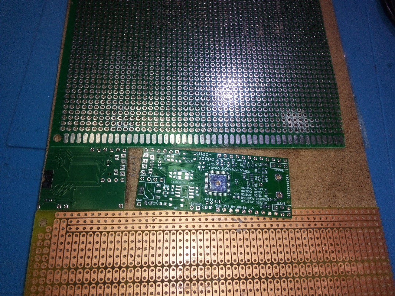
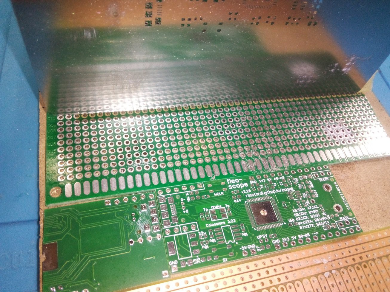
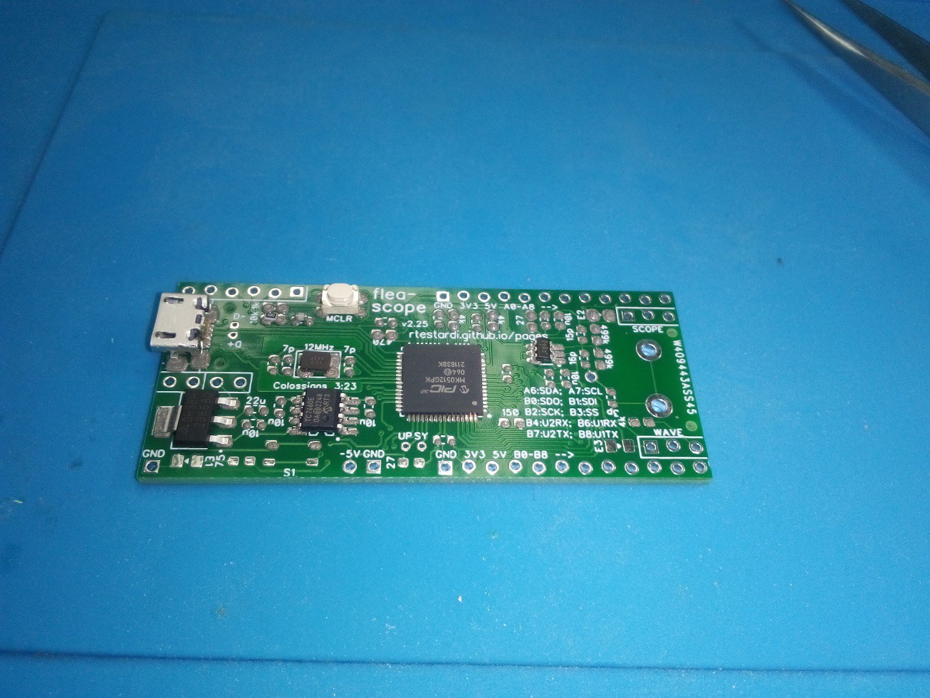
3Assemble the PCB
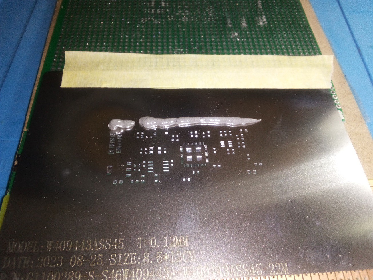
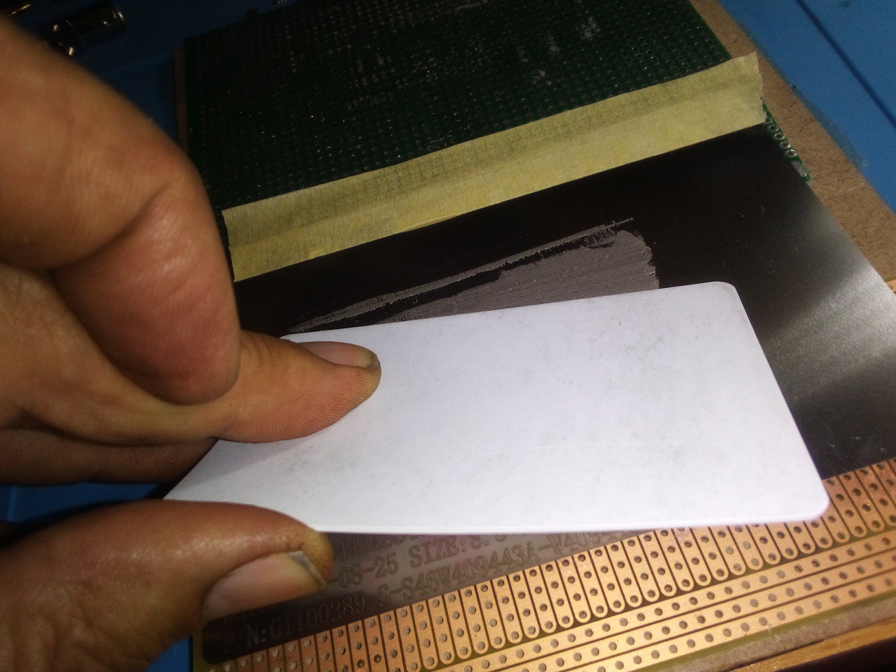
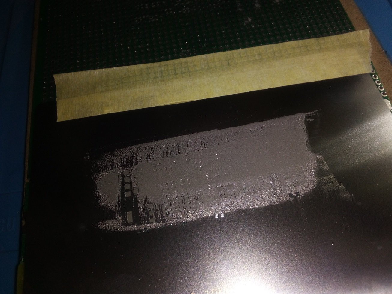
I usually build the boards with a solder paste stencil (also from pcbway.com) using Chip Quik SMDLTLFP solder paste and a Kester 2331-ZX flux pen and Kester Pocket-Pak lead-free rosin-core solder for any rework; I clean boards after rework with isopropyl alcohol and a toothbrush followed by running water.
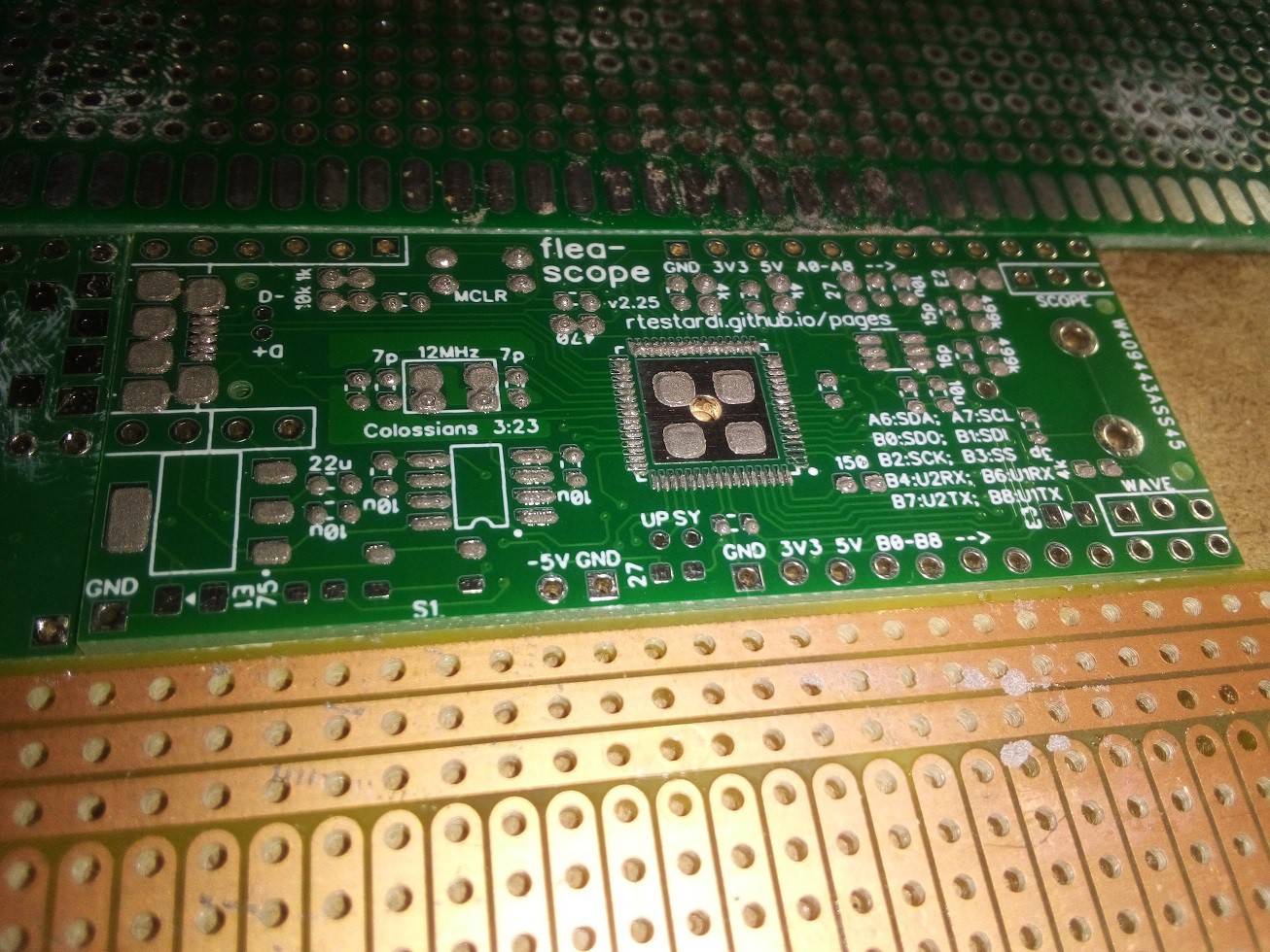
Inside the zip is also an assembly drawing showing you where each component goes; the PCB silkscreen also locates each component value for easy hand-assembly (unlabeled caps are 0.1uF bypass).
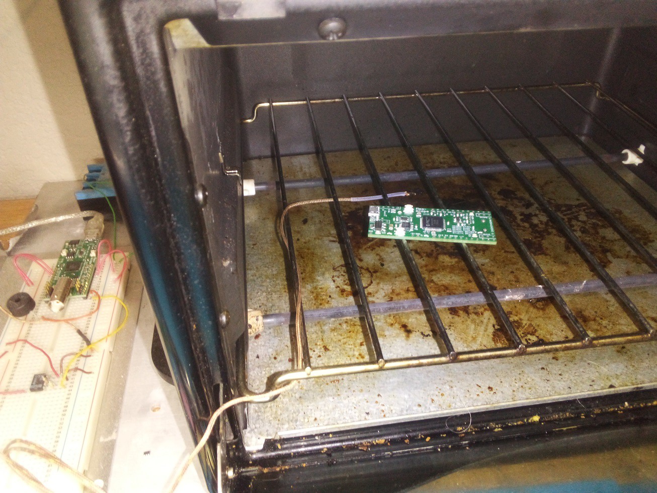
I reflow my boards in a toaster oven that is controlled by another Flea-Scope (see links -- I realize this is a chicken-and-egg problem -- you have to do the first board by hand -- just watch for the solder to melt).
![]()
![]()
![]()
![]()
![]()
![]()
![]()
![]()
-
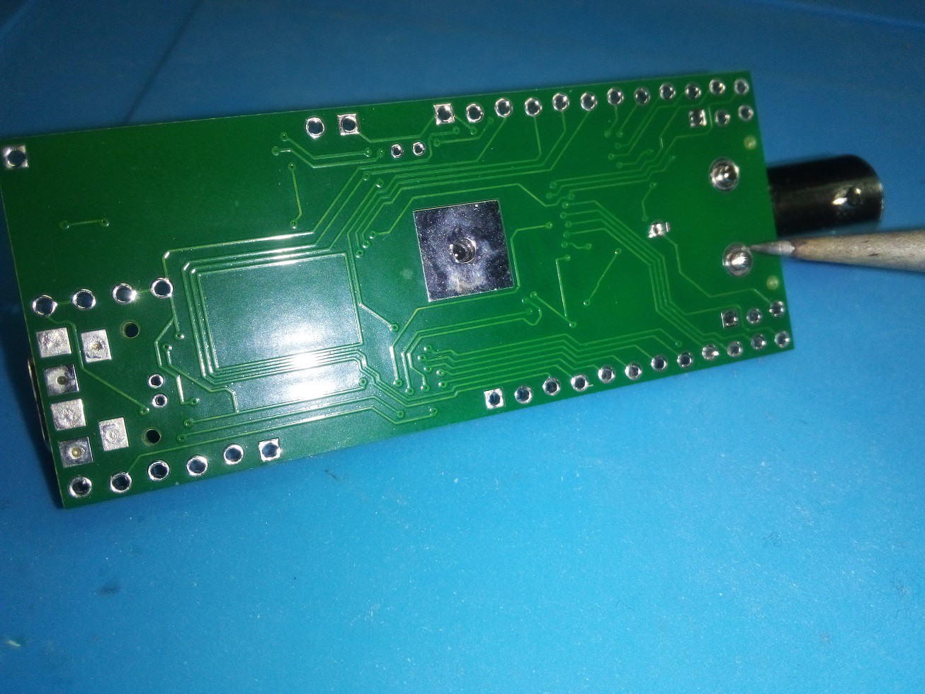
4Solder the BNC connector
The last assembly step, if desired, is to solder the BNC connector by hand on the board -- this is easier with a high-power soldering iron. I use an old Weller WES51 soldering iron.
Since this can be challenging, let me share a bit more of what I have found works! I start by soldering the thin middle pin, and then I make sure the BNC connector is flat on the board, before starting on the thick side pins. Then I solder one side pin for maybe 20 seconds -- this heats the whole BNC connector. Then I move to the other side pin before the first side is quite completely wetted/done, and solder the other side pin for 20-30 seconds, until wet. Then I return to the first side pin for another 10 seconds, until wet. This seems to work well, bringing both pins up to temperature, without either getting too hot. And finally, I check the white insulator on the thin middle pin, and make sure it has not melted back at all -- it should still be nicely rectangular -- if it has melted, I spent too much time in the soldering process, and heated the BNC connector too much.
![]()
-
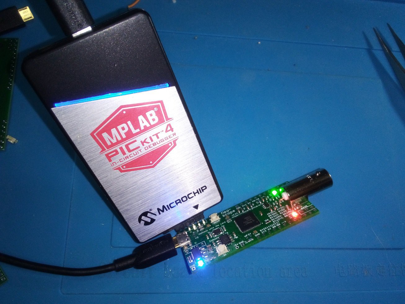
5Program the MCU
"pic32.X.27.production.hex", also attached, contains the firmware to program the Flea-Scope PIC32MK MCU. I use a Microchip PicKit 3 or PicKit 4 to program the MCU using the 6-pin ICSP header on the Flea-Scope board, and the cheaper "Snap" programmer works as well! I use Microchip MPLAB X v6.05 to control the programmer.
![]()
-
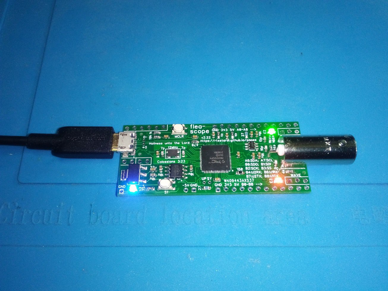
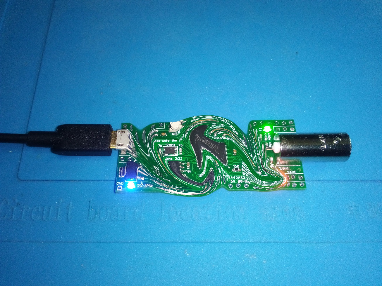
6Connect the PCB and Open the Graphical User Interface (GUI)
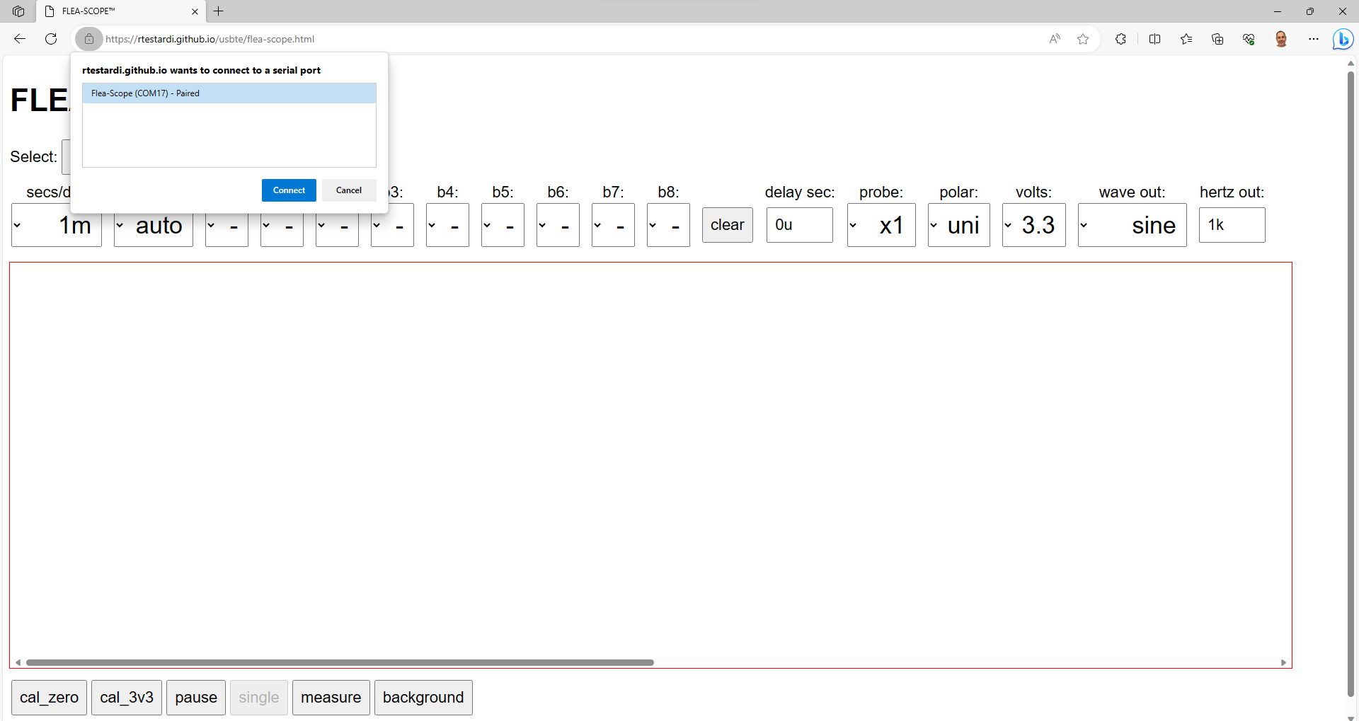
To use Flea-Scope, just connect it to a USB computer, tablet, or phone, and open the Flea-Scope GUI in Chrome or Edge and click "Start Connect". (I Test on Windows, Mac, ChromeOS, and Android.)
The Flea-Scope GUI is here: https://rtestardi.github.io/usbte/flea-scope.html
Flea-Scope will warn you if it is missing calibration values. Calibration is easy -- using the default "1m" secs/div and "auto" trigger level, first touch the probe to ground (available on silkscreened pins) and press the "cal_zero" button, then touch the probe to 3.3 volts (also available on silkscreened pins) and press the "cal_3v3" button. Done! You have to repeat calibration if you switch to x10 probe.
If you are concerned with ground loops (like if you are using an older computer and not a tablet or phone), you can also use a basic USB isolator in full speed mode like this one available from amazon, resulting in a full floating ground: Amazon.com: HiLetgo ADUM3160 B0505S 1500V USB to USB Voltage Isolator Module Support 12Mbps 1.5Mbps : Electronics
Note that for Ubuntu Linux, assuming username "ubuntu", to allow the browser to access USB serial ports, run these two commands:
usermod -a -G dialout ubuntu
usermod -a -G dialout rootthen log out and log back in.
![]()
![]()
![]()
-
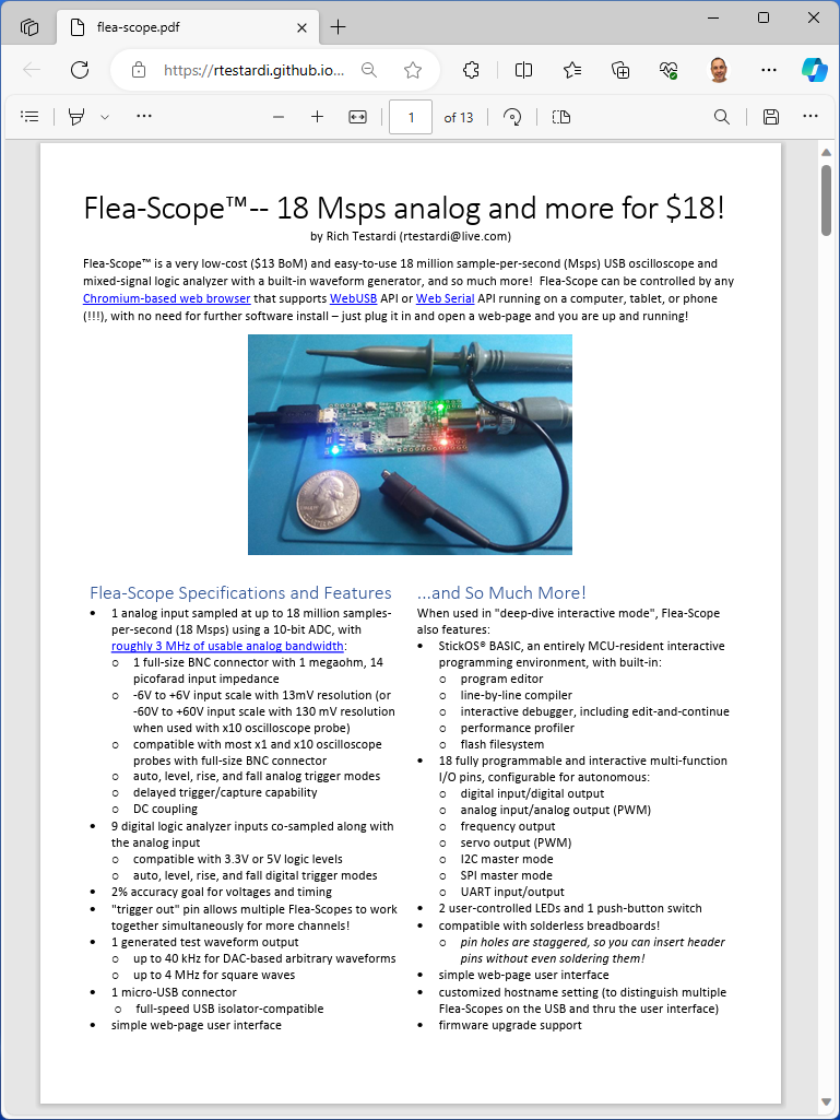
7See the User's Guide for More Info!
The Flea-Scope™ User's Guide (including some "how it works" internals and full specifications) is here: https://rtestardi.github.io/usbte/flea-scope.pdf
The Flea-Scope™ GUI is here: https://rtestardi.github.io/usbte/flea-scope.html
The Flea-Scope™ StickOS® BASIC Deep Dive User Interface is here: StickOS® BASIC (rtestardi.github.io)
And an unbelievable video explaining StickOS® BASIC is here: Part 1: An MCU-resident rapid prototyping and education environment for highly integrated MCUs - YouTube
The github repository for the GUI is: https://github.com/rtestardi/usbte
The github repository for the firmware and PCB is: https://github.com/rtestardi/StickOS2
The instructions to build a Simple-Simon Game using Flea-Scope™ are here: https://rtestardi.github.io/usbte/simon.pdf
The instructions to build a Toaster Oven Temperature Profile Controller are here: https://rtestardi.github.io/usbte/toaster.pdf
![]()
-
8Turn on and Troubleshooting Notes
Lots more assembly and test details are here: pcba.pdf (rtestardi.github.io)
I first visually look for shorts/opens, especially on the QFN or QFP and USB (shorts can be easily reworked with the Kester 2331-ZX flux pen; always clean and dry boards after rework; I use isopropyl alcohol and a toothbrush followed by running water).
I also look for flying components -- typically 0603's on their side because one pad did not wet...
Turn on
After assembly, the first thing I do is connect the Flea-Scope USB to the host computer and program the board using a pickit4 to download pic32.X.27.production.hex -- this operation tests the USB power and main regulator, as well as portions of the MCU and portions of the reset circuitry.
I then disconnect the pickit4.
After that, the blue LED on the board should be blinking steady at 1Hz and the two other LEDs (red and green) should be solid on -- this tests large portions of the MCU, including flash self-programming -- an error code flashed out the blue LED would be bad.
I press the reset button (labeled MCLR) and make sure the LEDs go out while the button is held -- this tests the rest of the reset circuitry -- I release the reset button and the blue LED on the board should be blinking steady at 1Hz again.
I then connect the main Flea-Scope GUI webpage (https://rtestardi.github.io/usbte/flea-scope.html) to the board -- I hit the "Connect", select the Flea-Scope, and click "Connect" to confirm -- the GUI should begin tracing, and all three LEDs should be blinking -- this tests USB data.
I then connect a x1 scope probe and calibrate ground by touching the probe to ground (silkscreen labeled) and pressing "cal_zero", and confirm a value near 14 in the GUI, and then calibrate 3.3V by touching the probe to 3.3V (also silkscreen labeled) and pressing "cal_3v3" and confirm a value near 259 in the GUI -- this confirms the negative supply rail as well as the passive pullup/down circuitry, as well as the op amp. (You have to repeat calibration if you switch to x10 probe, and the values should be near 28 and 270.)
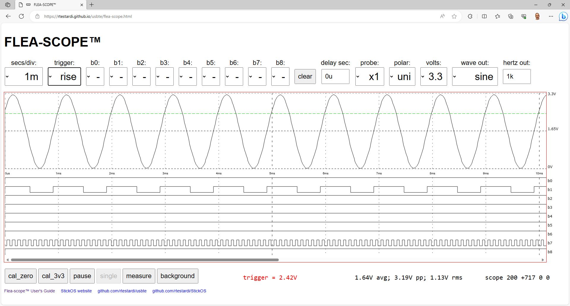
I touch the scope probe to the wave output pin and make sure I see the 1 kHz sine wave (default for GUI is 1 ms/division), and you should see 10 cycles of the sine wave, all approaching (but not quite touching) the top and bottom of the display area -- this tests wave circuitry continuity.
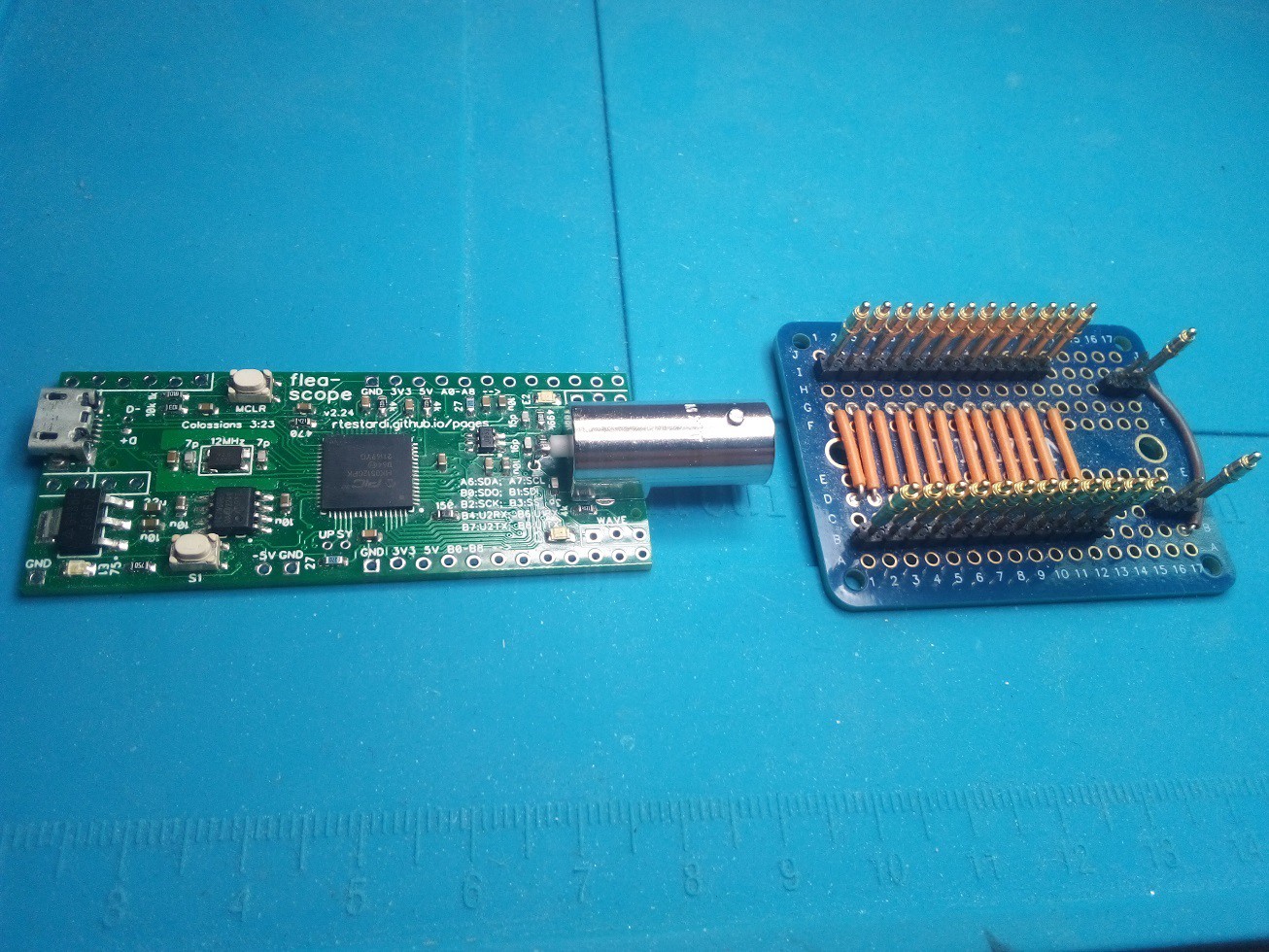
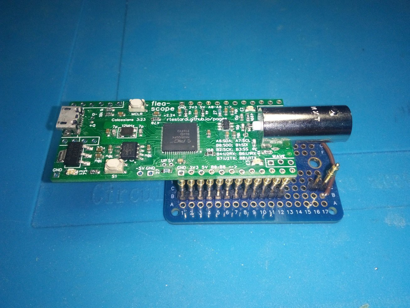
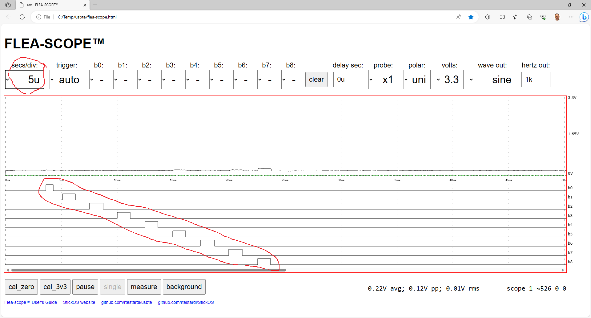
I finally put the board on the test bed (which simply connects all "A" pins to the corresponding "B" pins, switch the GUI to 5 us/division, and press the "test" button (labeled S1) -- you should see all nine digital signal lines (b0 thru b8) pulse in sequence as below -- this tests the remaining MCU pins for shorts/opens.
(Notice there is a bit of noise induced on the floating analog input during this test, especially by "b8", but this is not a problem as the scope is careful to keep these signals drivel low during actual operation, forming a quasi-ground plane on the back-side of the board.)
Diagnostics
* check power supply; measure 5V to ground, 3.3V to ground, -5V to ground (all three power supply pins are silkscreened)
* check clocks; SY testpoint (system clock divided by 1024) should be 117.2 kHz, UP testpoint (USB PLL divided by 1024) should be 46.9 kHz
* check USB pull-ups; D- testpoint should be ~0V, D+ testpoint should be ~3V (both of these are controlled by the MCU firmware, and allow the host computer to detect the Flea-Scope presence)![]()
![]()
![]()
![]()
Flea-Scope USB Oscilloscope ($18, 18 Msps, WebUSB)
Flea-Scope™ is a very low-cost ($18 at Elecrow) and easy-to-use 18 Msps USB oscilloscope and mixed-signal logic analyzer.
Discussions
Become a Hackaday.io Member
Create an account to leave a comment. Already have an account? Log In.